Journal of Materials Science and Chemical Engineering
Vol.03 No.05(2015), Article ID:56559,10 pages
10.4236/msce.2015.35010
Photoelectrochemical Studies on High Specific Capacitance-Photoactive Interfaces Based on Poly 3,4- Ethylenedioxythiophene/Metal Oxides Assemblies
Kasem K. Kasem*, William Bennett, Heather Ramey, Nick Daanen
School of Science, Indiana University Kokomo, Kokomo, IN, USA
Email: *kkasem@iuk.edu
Copyright © 2015 by authors and Scientific Research Publishing Inc.
This work is licensed under the Creative Commons Attribution International License (CC BY).
http://creativecommons.org/licenses/by/4.0/


Received 6 March 2015; accepted 18 May 2015; published 22 May 2015
ABSTRACT
Inorganic/organic interfaces (IOI) consist of TiO2/PEDOT (poly 3,4-ethylenedioxythiophene) and [PMo12O40 ]3− or MoO3/PEDOT were subject to photoelectrochemical studies in both aqueous nano- suspensions and in thin solid films. The effects PEDOT modifier caused on the photoelectrochemical behavior of the IOI were investigated using [Fe(CN)6]4− as the photoactive hydrated electron donor agent. Results show that native PEDOT or PEDOT doped with MoO3 thin films increased charge storage capability evident by the high capacitive current. In the case of nano suspensions composed of TiO2/PEDOT the adsorption process of [Fe(CN)6]3− (photolysis product) control of the photoactivity outcome of the IOI assemblies. TiO2/PEDOT shows a lower heterogeneous photochemical response than native TiO2 in short term photolysis times. At longer photolysis times the IOI shows photoactivity greater than that of native TiO2. The interface activities were explained by analyzing the IOI junction characteristics, such as electron affinity, work function and hole/elec- trons barrier heights. The aqueous nano-systems retained moderate stability as indicated by the reproducibility of their photocatalytic activities. Both [Fe(CN)6]4− and PEDT contributed to the stability of native TiO2 surfaces.
Keywords:
Inorganic/Organic Semiconductors, Photoelectrochemical Cells, High Capacitive Assembly

1. Introduction
Polymers of conjugated organic compounds possess large molar absorptivity which is a desired quality in the absorption of light. This was an attractive characteristic for the use of these polymers in photovoltaic cells for solar energy harvesting, conversion and storage devices. Some of these polymers can be prepared electrochemically under very controllable conditions. The use of electrochemical polymerization methods made it is possible to modify surfaces and create photoactive interfaces. Surface modification can be a very effective way to create or eliminate defects and alter the energy band at inorganic/organic Interfaces. This will also alter the donor/ac- ceptor character of the IOI assemblies. Poly (3,4-ethylenedioxythiophene) (PEDOT) and its derivatives are well known as very stable conducting polymers [1] - [6] . As p-conjugated conducting polymers are excellent materials for creation of photoactive interfaces due to their ability to act as electron reservoirs, thereby giving rise to colored, mixed-valence state species while retaining their structural integrity. PEDOT has been prepared by several methods including emulsion techniques [1] , protein-mediated synthesis [2] , vapor phase polymerization [3] , solid state synthesis [4] , and by electrochemical synthesis [5] [6] .
PEDOT was subject to several investigations related to its applications in as flexible electrodes for energy storage and conversion [7] , hybrid super capacitor materials [8] , for use in dye-sensitized solar cells [9] , as chemiresistive sensors for detection of nitro-aromatics [10] , for dip-pen nanolithography [11] , and PEDOT-based nano-coatings for tissue regeneration has been investigated [12] . These materials have also been used for construction of inorganic/organic interfaces, where the reversible electro-switchable luminescence in thin films of organic-inorganic hybrid assemblies was reported [13] .
The great stability of PEDOT and its ability to act as electron donor (p-Type) substantiate the interest to investigate its usefulness in conjunction with the well-known stable photoactive semiconductor TiO2, and in conjunction with the multi-redox active centers MoO3. The performance of TiO2/PEDOT, and MoO3/PEDOT assembly interfaces will be examined monitoring their effectiveness in charge separation, exchange, storage, and transfer.
2. Experimental
2.1. Reagents
All the reagents were of analytical grade. All of the solutions were prepared using deionized water, unless otherwise stated. TiO2, TiO2/PEDOT were either in nanoparticulate form or thin solid films.
2.2. Preparations
1-PEDOT: This polymer was prepared by both electrochemical and photochemical techniques:
2.2.1. Electropolymerization of EDOT
Polymer thin films were generated electrochemically using cyclic voltammetry (CV) by repetitive cycling of the FTO electrode potential at a scan rate 0.10 V/s between −1.5 and 1.2 V vs Ag/AgCl in acetonitrile solution of 0.2 M LiClO4 containing 10 mM of the monomer.
2.2.2. Preparation of TiO2/PEDOT/Interface
Colloidal suspensions of TiO2/PEDOT interface were prepared as follows: 0.05 g of TiO2 nanoparticles prepared as reported previously [14] were suspended in the solution of EDOT in acetonitrile. The mixture was subjected to a 10 minute sonication followed by stirring for 1.0 hour to allow maximum adsorption of EDOT on the TiO2 nanoparticles. The excess EDOT was removed by centrifugation. TiO2 with adsorbed EDOT was re-suspended in deionized-water containing a few drops of 30% H2O2 and subjected to UV radiation under constant stirring for 3 hours. The resultant TiO2/PEDOT was rinsed several times with deionized water and allowed to dry at 120˚C for 2 hours.
2.2.3. Electropolymerization of EDOT/MoO3
Thin films of PEDOT containing clusters of MoO3 were generated electrochemically using cyclic voltammetry (CV) by repetitive cycling of the FTO electrode potential at a scan rate 0.10 V/s between −0.4 and 1.2 V vs Ag/AgCl in mixed solvent of dioxane/water containing 1 mM of the monomer EDOT, 0.5 mM of phosphomolybdic acid (H3PMo12O40) and 0.5 M H2SO4.
2.2.4. Deposition of TiO2/PEDOT Thin Solid Films
Thin solid films of TiO2 particles, modified with PEDOT (prepared as described in B) were suspended in acetonitrile solution of polyvinyl pyridine (PVP). The suspension was spread evenly over fluorine doped Tin oxide (FTO) slides (12.5 × 75 mm) and dried at 120˚C for 6 hours. The assembled electrode was transferred to a three-electrode cell containing the chosen buffer as the electrolyte and a Ag/AgCl and Pt electrodes as the reference and counter electrode respectively.
2.3. Instrumentation
All electrochemical experiments were carried out using a BAS 100 W electrochemical analyzer (Bioanalytical Co). Steady state reflectance spectra were obtained using Shimadzu UV-2101 PC. Irradiation was performed with a solar simulator 300 watt xenon lamp (Newport) with an IR filter. Photoelectrochemical studies on thin solid film were performed on an experimental setting as illustrated in (Diagram 1(a)). The electro/photolysis cell was a one-compartment Pyrex cell with a quartz window (Diagram 1(b)) facing the irradiation source [15] . The working electrode, a 10.0 cm2 platinum gauze cylinder, had a solution volume of 100 mL. Suspensions were stirred with a magnetic stirrer during the measurements. A Ag/AgCl/Cl reference electrode was also fitted into this compartment. A 10-cm2 platinum counter electrode was housed in a glass cylinder sealed in one end with a fine-porosity glass frit.
Photolysis of [Fe(CN)6]4− generated hydrated electrons and [Fe(CN)6]3−. The potential of the working electrode was fixed at 100 mV more negative than the reduction potential of [Fe(CN)6]3− to guarantee full reduction of ferricyanide. The current due to the reduction of [Fe(CN)6]3− collected by the working electrode during the photolysis process is a measure of photocurrent. The measured photocurrent was normalized considering two photons per one hydrogen molecule, and was used to calculate the number of moles of hydrogen generated per square meter per hour of illumination.
Unless otherwise stated, all experiments were performed at room temperature 25˚C ± 1˚C.
3. Results and Discussions
3.1. Electropolymerization of EDOT
Controlled deposition of polymer film took place by repetitive cycling of the FTO electrode potential at scan rate of 0.10 V/s between −1.5 and 1.2 V vs Ag/AgCl in acetonitrile solution containing 10 mM of EDOT monomer and 0.5 M LiClO4. The results are displayed in Figure 1(a). The growth of the redox wave in the potential range −0.5 V to 1.0 V was an indicator for the buildup of EDOT films.
3.2. Electrochemical Behavior of PEDOT
The electrochemical behavior of PEDOT was investigated by cycling the potential of FTO modified with PEDOT between −1.0 to 1.40 V vs Ag/AgCl in acetonitrile containing 0.5 M LiClO4 at scan rate 0.10 V/s. The results are displayed in Figure 1(b). It can be noticed that the resulted CV shows an oxidation wave at ≈−0.1 V
 (a) (b)Diagram 1. Photoelectrochemical cells. (a) for thin film studies; (b) for photolysis of nano-suspensions.
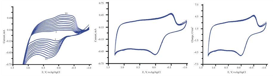 (a) (b) (c)
Figure 1. (a) electropolymerization of 3,4 EDT in ACN containing LiClO4; (b) CV of ITO/PEDT in ACN/LiClO4 only, scan rate 100 mV/s; (c) capacitive charge density for FTO/PEDT in ACN containing LiClO4.
and reduction wave at ≈−0.5 V. it is worth noticing also the very high capacitive current on the thin film of PEDOT. The plot of capacitance vs potential is displayed in Figure 1(c). The large capacitive currents observed for FTO/PEDPT suggest that this assembly could be used as electrodes for super capacitors.
3.3. Band-Energy Map of PEDOT
While the band gap of PEDOT depends on the level of doping [16] which controls the absorption peak of the polymer, we choose to use the absorption peak of a neutral polymer film which conditioned at a potential more negative than its first oxidation potential (˂−0.3 V vs Ag/AgCl). The absorption peak under these conditions was found to be at 580 nm, corresponding to a band gap of 2.15 eV. Ionization potential (IP) and electron affinity (EA) are important parameters to draw the energy map of PEDOT along with the band gap (Eg). These parameters are also needed to explain the electrical and optical properties of the film. Relating electrochemical data such as the onset oxidation potential (E’ox), the onset reduction potential (E’Red), and the band gap leads to an understanding of the integrated energy diagram of the film. Onset potentials can be estimated from the intersection of the two tangents drawn at the rising oxidation current and the background current in the CV using the following formula [17] :
 (1)
(1)
An Ag/AgCl was used as a reference electrode (E˚ = 0.197 V ≈ 0.2 V vs SHE), therefore EAg/AgCl ≈ ESHE + 0.20, and when Evac ≈ 0, the above Equation can be rewritten as follows:
 (2)
(2)
As  where
where  is oxidation potential onset.
 (3)
(3)
where E'ox is oxidation potential onset relative to Ag/AgCl. Substitution from Equation (2) to (3), results in:
 (4)
(4)
Considering that the energy gap between HOMO (valence band) and LUMO (conduction band) to the band gap (Eg), and the energy gap between the LUMO and vacuum level is the electron affinity (EA), we can write the following Equation:
 (5)
(5)
By integrating the spectral absorption information with the data obtained from Figure 1 and Equations (1)-(5) and consideration of absorption spectra of PEDOT, a list of photo-electrochemical data for TiO2 and PEDOT were deduced and summarized in Table 1. The quantities are listed without signs to reflect only their magnitude. The fact that the hole barrier height is large (≈2 eV) and greater than the electron barrier height may indicate that charge injection is mediated at the IOI interface through hole transfer.
3.4. Photoelectrochemical Behavior of TiO2/PEDOT
Thin Solid Form
Cycling the potentials of FTO/TIO2/ PEDOT in 0.2 M phosphate buffer (pH 6) in the dark and under illumination are displayed in Figure 2. The increase in the reported current during the cathodic scan at 0.2 V vs Ag/AgCl gives an approximate value of the flat band potential of the ITO/TiO2/PEDOT/aqueous electrolyte interface. The variations of photocurrent vs time were studied by measuring the photocurrent generated by this assembly upon illumination at −0.3 V vs Ag/AgCl he results are displayed in Figure 3, which indicates that a large photocurrent is produced at the first illumination, which dropped in inconsistent ways during the next conductive illumination periods. Such observation indicates changes in the course of charge separation at this IOI assembly.
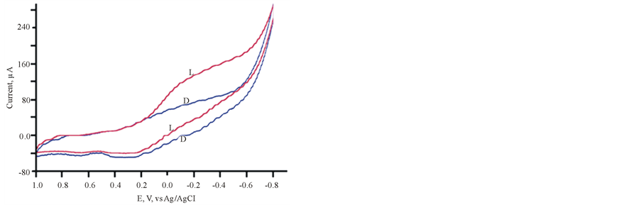
Figure 2. CV of FTO/PEDT in phosphate buffer pH 6 L (light), D (Dark).
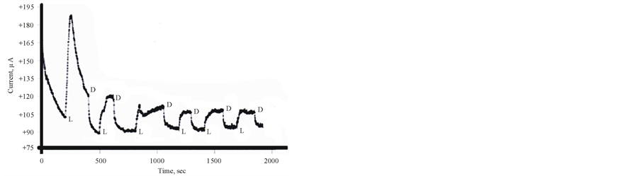
Figure 3. Photocurrent-time curve for ITO/TiO2/PEDOT in Phosphate buffer pH 6 containing 10 mM [Fe(CN)6]3− at −0.5 V vs Ag/AgCl L & D donates to Light and dark respectively.

Table 1. photoelectrochemical data for TiO2/PEDOT assembly.
1Hole barrier height = HOMO(PEDOT) − VB(TiO2); 2electron barrier height = LUMO(PEDOT) − CB(TiO2).
3.5. Effect of Electrolyte Anions on the Photoelectrochemical Behavior of the IOI Assembly
The results of investigation of the photoelectrochemical behavior of ITO/TiO2/PEDOT in 0.20 M acetate pH 6 buffers are displayed in Figure 4 and Figure 5. Figure 4 shows that the current recorded under the dark conditions is greater than that recorded under illumination which is opposite to the behavior recorded in Figure 2. Furthermore, opposite behavior also can be seen by comparing results displayed in Figure 3 and Figure 5. The change from phosphate ( ) buffer to acetate buffer (CH3COO−) clearly alters the nature of the donor/ac- ceptor process and consequently alters the mechanism of charge separation and transfer at the IOI electrolyte interface. Also, the photocurrent reported in presence of acetate (Figure 5) is steady and constant, which is not the case with the photocurrent recorded in phosphate buffer.
3.6. Photoelectrochemical Behavior of TiO2/PNR Aqueous Suspensions
The theory of the photolysis of aqueous [Fe(CN)6]4− has been discussed elsewhere [18] . In this study, aqueous suspensions of pure TiO2 and TiO2 surface-modified with PEDOT in 0.2 M phosphate buffer at pH 6 containing 0.010 M [Fe(CN)6]4− were subject to the photolysis process. The potential of the Pt collector electrode was kept constant at 0.000 V vs Ag/AgCl. The results are displayed in Figure 6. Peak A in Figure 6 is the result of total electrochemical reduction of any [Fe(CN)6]3− shown in the following photoreaction:

Figure 4. CV of FTO/TiO2/PEDT in Acetate buffer pH 6.

Figure 5. Photolysis FTO/TiO2/PEDT thin film in Acetate buffer pH 6 containing 10 mM [Fe(CN)6]4− (a) at −0.50 V vs Ag/AgCl (b) at −0.30V vs Ag/AgCl (L and D donate to Light and dark).
 (6)
(6)
In presence of semiconductor nanoparticles (SC) the following photoreduction reaction takes place:
 (7)
(7)
The number of photons consumed in this photoreaction can be calculated from the integration of the green zone portion in Figure 6. The mechanism of the reaction in Equation (7) has been previously discussed [18] . The data listed in Table 2 clearly show that modified TiO2 with PEDOT was more efficient than in the process of photoreduction of [Fe(CN)6]3− on native TiO2.
3.7. Doping PEDOT with MoO3
Thin solid films of PEDOT doped with MoO3 have been achieved by the occlusion electrodeposition process as described in experimental section. The results are displayed in Figure 7. The growth of both anodic and cathodic peaks currents is indication of the buildup PEDOT impregnated with MoO3. The resulting film has dark bluish appearance. It is well known that [PMo12O40]3− decomposes to produce MoO3 [19] [20] .
3.8. Electrochemical Behavior of ITO/MoO3/PEDOT
The cyclic voltammetry (CV) of ITO/MoO3/PEDOT assembly in 0.5 M H2SO4 (50% dioxane/water) mixture is displayed in Figure 8 (Trace 1). Occlusion of MoO3 into PEDOT sharply increases the capacitive current and stored greater amount of charge. This observation is supported by the fact that Trace 2 in this figure is the CV for the ITO/PEDOT in the electrolyte only as also illustrated in Figure 1(b). The comparison displayed in Figure 8 confirms the fact that MoO3 is strong electron storage capacity. The large amount of charge represented by the area of Trace 1 compared to that Trace 2, clearly recommend that the MoO3/PEDOT assembly can enhance energy storage in both battery and capacitor charge.

Figure 6. Photolysis of TiO2/PEDT in Phosphate buffer pH 6 (a) in aqueous containing 10 mM [Fe(CN)6]4− (b) as in A + addition of nanoparticle suspensions of TiO2/PEDT (L and D donate to Light and dark). Green zone represents the photoreduction.
Table 2. Photolysis of Aqueous 10 mM of K4[Fe(CN)6] (Ref) in 0.2M  (pH = 6.0) in presence of TiO2/PEDOT nanoparticle suspensions.
1Calculated from integrating area under Curve A (Figure 6). 2Calculated by integrating yellow zone area and green zone area (Figure 6). 3Calculated by the ration of photoreduction/EC reduction.

Figure 7. (a) Electrodeposition of [PMo12O40]3− in FTO/PEDOT in aqueous H2SO4/Dioxane solvent. Inset (b) (scan number is indicated in the figure).

Figure 8. 1) CV of ITO/PEDT/Mo12O36 in aqueous H2SO4/ Dioxins only, scan rate 100 mV/s; 2) CV of ITO/PEDT in aqueous H2SO4/Dioxins only , scan rate 100 mV/s.

Figure 9. Energy band alignment between TiO2 and PEDOT.
4. Conclusions
The TiO2 used in this study is a p-type semiconductor and the properties of PEDOT listed in Table 1 indicate that it is electron donor, its low electron affinity suggests that an Iso p-p junction [21] is formed by creation of a hole accumulation layer in one side and a hole depletion layer on the counter side. The fact that holes in PEDOT’s HOMO are at more negative potential than that in TiO2’s VB (2.7 eV) as shown in Figure 9, suggests that the charge injection/transfer mechanism took place via hole transfer. This is because more negative potential will attract TiO2 holes to PEDOT side.
The band-energy map of PEDOT has a staggered-band alignment with TiO2 (Figure 9(b)) in IOI assemblies as indicated by both electrochemical and spectroscopic data. Such staggered band alignments facilitate the photo-activity of both organic and inorganic semiconductors through hybrid―sub bands leading to more capturing of incident photons at this IOI assembly.
Our studies demonstrated that PEDOT modification of TiO2 enhances the photoactivities of TiO2/PEDOT assembly as indicated by the data listed in Table 2. Furthermore, PEDOT/[PMo12O40]3− exhibit high capacitive storage interface that is very useful in energy storage devices.
Cite this paper
Kasem K. Kasem,William Bennett,Heather Ramey,Nick Daanen, (2015) Photoelectrochemical Studies on High Specific Capacitance-Photoactive Interfaces Based on Poly 3,4- Ethylenedioxythiophene/Metal Oxides Assemblies. Journal of Materials Science and Chemical Engineering,03,88-97. doi: 10.4236/msce.2015.35010
References
- 1. Behniafar, H. and Yousefzadeh, D. (2015) Chemical Synthesis of PEDOT/Ag Nanocomposites via Emulsion Technique in Silver Colloid. Designed Monomers and Polymers, 18, 6-11.
http://dx.doi.org/10.1080/15685551.2014.918018 - 2. Hira S.M. and Payne C.K. (2013) Protein-Mediated Synthesis of the Conducting Polymer PEDOT: PSS. Synthetic Metals, 176, 104-107.
http://dx.doi.org/10.1016/j.synthmet.2013.05.023 - 3. Shaplov, A.S., Ponkratov, D.O., Aubert, P.H., Lozinskaya, P.H., Plesse, C., Maziz, A., Vlasov, P.S., Vidal, F. and Vygodskii, Y.S. (2014) Truly Solid State Electrochromic Devices Constructed from Polymeric Ionic Liquids as Solid Electrolytes and Electrodes Formulated by Vapor Phase Polymerization of 3,4-ethylenedioxythiophene. Polymer, 55, 3385-3396.
http://dx.doi.org/10.1016/j.polymer.2014.04.013 - 4. Chen, L., Jin, J., Shu, X. and Xia, J. (2014) Solid State Synthesis of Poly(3,4-ethylenedioxythiophene) as Counter Electrode for Dye-Sensitized Solar Cell. Journal of Power Sources, 248, 1234-1240.
http://dx.doi.org/10.1016/j.jpowsour.2013.09.139 - 5. Carstens, T., Prowald, A., Zein El Abedin, S. and Endres, F. (2012) Electrochemical Synthesis of PEDOT and PPP Macroporous Films and Nanowire Architectures from Ionic Liquids. Journal of Solid State Electrochemistry, 16, 3479- 3485.
http://dx.doi.org/10.1007/s10008-012-1814-4 - 6. Kupis, J., Migdalski, J. and Lewenstam, A. (2013) Electrochemical Properties of the Poly(3,4-ethylenedioxythiophene) Doped with Taurine Ligands. Electroanalysis, 25, 195-203.
http://dx.doi.org/10.1002/elan.201200377 - 7. Chu, C.Y., Tsai, C.J.T. and Sun, C.L. (2012) Synthesis of PEDOT-Modified Graphene Composite Materials as Flexible Electrodes for Energy Storage and Conversion Applications. International Journal of Hydrogen Energy, 37, 13880- 13886.
http://dx.doi.org/10.1016/j.ijhydene.2012.05.017 - 8. Ghaffari, M., Kosolwattana, S., Zhou, Y., Lachman, N., Lin, M., Bhattacharya, D., Gleason, K.K., Wardle, B.L. and Zhang, Q.M. (2013) Hybrid Supercapacitor Materials from Poly(3,4-ethylenedioxythiophene) Conformally Coated Aligned Carbon Nanotubes. Electrochimica Acta, 112, 522-528.
http://dx.doi.org/10.1016/j.electacta.2013.08.191 - 9. Pringle, J., Armel, V., Forsyth, M. and MacFarlane, D.R. (2010) In PEDOT Coated Plastic Counter Electrodes for Dye-Sensitized Solar Cells. International Chemical Congress of Pacific Basin Societies, Honolulu, 15-20 December 2010, MATNANO-18.
- 10. Rattan, S., Singhal, P. and Verma, A.L. (2013) Synthesis of PEDOT:PSS (Poly(3,4-ethylenedioxythiophene))/Poly (4-styrene sulfonate)/NGPs (Nanographitic Platelets) Nanocomposites as Chemiresistive Sensors for Detection of Nitroaromatics. Polymer Engineering & Science, 53, 2045-2052.
- 11. Wagner, M., O’Connell, C.D., Harman, D.G., Sullivan, R., Ivaska, A., Higgins, M.J. and Wallace, G.G. (2013) Synthe- sis and Optimization of PEDOT:PSS Based Ink for Printing Nanoarrays Using Dip-Pen Nanolithography. Synthetic Metals, 181, 64-71.
http://dx.doi.org/10.1016/j.synthmet.2013.08.012 - 12. Karagkiozaki, V., Karagiannidis, P.G., Gioti, M., Kavatzikidou, P., Georgiou, D., Georgaraki, E. and Logothetidis, S. (2013) Bioelectronics Meets Nanomedicine for Cardiovascular Implants: PEDOT-Based Nanocoatings for Tissue Regeneration. Biochimica et Biophysica Acta (BBA)—General Subjects, 1830, 4294-4304.
http://dx.doi.org/10.1016/j.bbagen.2012.12.019 - 13. Zhai, Y.L., Jin, L.H., Zhu, C.Z., Hu, P., Han, L., Wang, E. and Dong, S.J. (2012) Reversible Electroswitchable Lumi- nescence in Thin Films of Organic-Inorganic Hybrid Assemblies. Nanoscale, 4, 7676-7681.
http://dx.doi.org/10.1039/c2nr32623j - 14. Peter, L.M., Upul Wijayantha, K.G., Jason Riley, D. and Waggett, J.P. (2003) Band-Edge Tuning in Self-Assembled Layers of Bi2S3 Nanoparticles Used to Photosensitize Nanocrystalline TiO2. Journal of Physical Chemistry B, 107, 8378-8381.
http://dx.doi.org/10.1021/jp030334l - 15. Kasem, K. and Dahn, M. (2010) Photodissocaiation of Water Using Colloidal Nanoparticles of Doped Titanium (IV) Oxide Semiconductors for Hydrogen Production. Current Science, 99, 1087-1092.
- 16. Kvarnstrom, C., Neugebauer, H., Blomquist, S., Ahonen, H.J., Kankare, J. and Ivaska, A. (1999) In Situ Spectroelec- trochemical Characterization of Poly(3,4-ethylenedioxythiophene). Electrochimica Acta, 44, 2739-2750.
http://dx.doi.org/10.1016/S0013-4686(98)00405-8 - 17. Roman, L.S., Hummelgen, I.A., Nart, F.C., Peres, F.C. and de Sa, E.L. (1998) Determination of Electroaffinity and Ionization Potential of Conjugated Polymers via Fowler-Nordheim Tunneling Measurements: Theoretical Formulation and Application to Poly (p-Phenylene vinylene). Journal of Chemical Physics, 105, 10614-10620.
http://dx.doi.org/10.1063/1.472947 - 18. Kasem, K. and Finney, A. (2013). Photoelectrochemical Studies on CdS/Poly Ethyl-Aniline Interfaces. International Journal of Chemistry, 5, 76-86.
http://dx.doi.org/10.5539/ijc.v5n3p76 - 19. Nair, H., Miller, J.T., Stach, E.A. and Baertsch, C.D. (2010). Mechanism of Dynamic Structural Reorganization in Polyoxometalate Catalysts. Journal of Catalysis, 270, 40-47.
http://dx.doi.org/10.1016/j.jcat.2009.12.007 - 20. Borras-Almenar, J.J., Coronado, E., Müller, A. and Pope, M. (2001) Polyoxometalate Molecular Sciences. Liuwer Academic Publisher, Dordrechi.
- 21. Wang, H.B. and Yan, D.H. (2010) A Heterojunction Is an Interface between Two Semiconductor Materials of Dif- fering Energy. NGP Asia Materials, 2, 69-78.
NOTES

*Corresponding author.