Paper Menu >>
Journal Menu >>
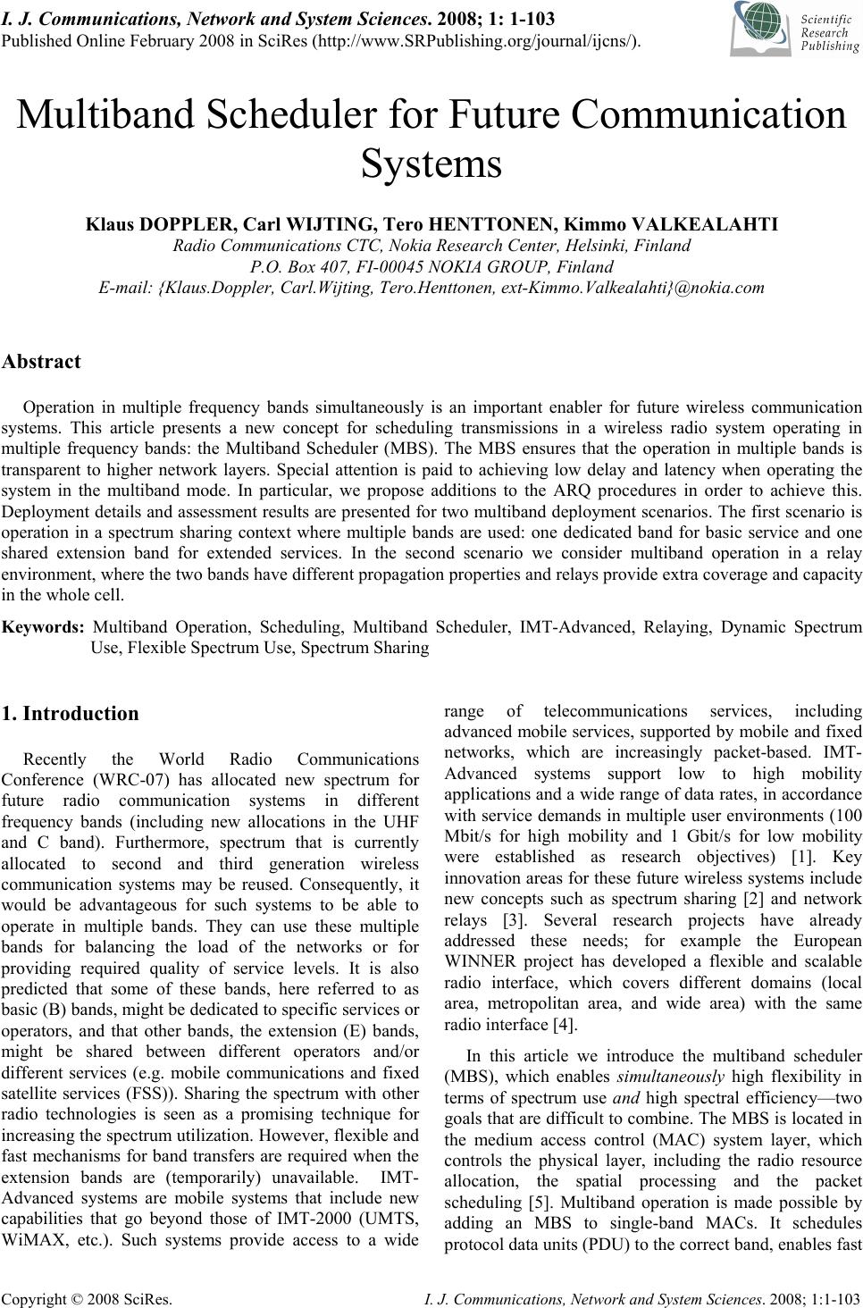 I. J. Communications, Network and System Sciences. 2008; 1: 1-103 Published Online February 2008 in SciRes (http://www.SRPublishing.org/journal/ijcns/). Copyright © 2008 SciRes. I. J. Communications, Network and System Sciences. 2008; 1:1-103 Multiband Scheduler for Future Communication Systems Klaus DOPPLER, Carl WIJTING, Tero HENTTONEN, Kimmo VALKEALAHTI Radio Communications CTC, Nokia Research Center, Helsinki, Finland P.O. Box 407, FI-00045 NOKIA GROUP, Finland E-mail: {Klaus.Doppler, Carl.Wijting, Tero.Henttonen, ext-Kimmo.Valkealahti}@nokia.com Abstract Operation in multiple frequency bands simultaneously is an important enabler for future wireless communication systems. This article presents a new concept for scheduling transmissions in a wireless radio system operating in multiple frequency bands: the Multiband Scheduler (MBS). The MBS ensures that the operation in multiple bands is transparent to higher network layers. Special attention is paid to achieving low delay and latency when operating the system in the multiband mode. In particular, we propose additions to the ARQ procedures in order to achieve this. Deployment details and assessment results are presented for two multiband deployment scenarios. The first scenario is operation in a spectrum sharing context where multiple bands are used: one dedicated band for basic service and one shared extension band for extended services. In the second scenario we consider multiband operation in a relay environment, where the two bands have different propagation properties and relays provide extra coverage and capacity in the whole cell. Keywords: Multiband Operation, Scheduling, Multiband Scheduler, IMT-Advanced, Relaying, Dynamic Spectrum Use, Flexible Spectrum Use, Spectrum Sharing 1. Introduction Recently the World Radio Communications Conference (WRC-07) has allocated new spectrum for future radio communication systems in different frequency bands (including new allocations in the UHF and C band). Furthermore, spectrum that is currently allocated to second and third generation wireless communication systems may be reused. Consequently, it would be advantageous for such systems to be able to operate in multiple bands. They can use these multiple bands for balancing the load of the networks or for providing required quality of service levels. It is also predicted that some of these bands, here referred to as basic (B) bands, might be dedicated to specific services or operators, and that other bands, the extension (E) bands, might be shared between different operators and/or different services (e.g. mobile communications and fixed satellite services (FSS)). Sharing the spectrum with other radio technologies is seen as a promising technique for increasing the spectrum utilization. However, flexible and fast mechanisms for band transfers are required when the extension bands are (temporarily) unavailable. IMT- Advanced systems are mobile systems that include new capabilities that go beyond those of IMT-2000 (UMTS, WiMAX, etc.). Such systems provide access to a wide range of telecommunications services, including advanced mobile services, supported by mobile and fixed networks, which are increasingly packet-based. IMT- Advanced systems support low to high mobility applications and a wide range of data rates, in accordance with service demands in multiple user environments (100 Mbit/s for high mobility and 1 Gbit/s for low mobility were established as research objectives) [1]. Key innovation areas for these future wireless systems include new concepts such as spectrum sharing [2] and network relays [3]. Several research projects have already addressed these needs; for example the European WINNER project has developed a flexible and scalable radio interface, which covers different domains (local area, metropolitan area, and wide area) with the same radio interface [4]. In this article we introduce the multiband scheduler (MBS), which enables simultaneously high flexibility in terms of spectrum use and high spectral efficiency—two goals that are difficult to combine. The MBS is located in the medium access control (MAC) system layer, which controls the physical layer, including the radio resource allocation, the spatial processing and the packet scheduling [5]. Multiband operation is made possible by adding an MBS to single-band MACs. It schedules protocol data units (PDU) to the correct band, enables fast 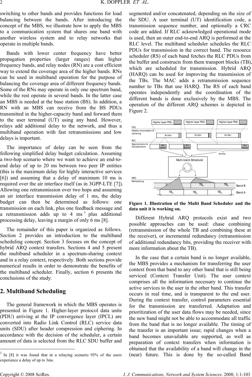 2 K. DOPPLER ET AL. Copyright © 2008 SciRes. I. J. Communications, Network and System Sciences. 2008; 1:1-103 switching to other bands and provides functions for load balancing between the bands. After introducing the concept of the MBS, we illustrate how to apply the MBS to a communication system that shares one band with another wireless system and to relay networks that operate in multiple bands. Bands with lower center frequency have better propagation properties (larger ranges) than higher frequency bands, and relay nodes (RN) are a cost efficient way to extend the coverage area of the higher bands. RNs can be used in multiband operation for the purpose of balancing the coverage area of different frequency bands. Some of the RNs may operate in only one spectrum band, while the rest operate in several bands. In the latter case an MBS is needed at the base station (BS). In addition, a RN with an MBS can receive from the BS PDUs transmitted in the higher-capacity band and forward them to the user terminal (UT) using any band. However, relays add additional delay to the network, and thus a multiband operation with fast retransmissions and low delays is important. The importance of delay can be seen from the following simplified delay budget calculation. Assuming a two-hop scenario where we want to achieve an end-to- end delay of up to 20 ms between two peer IP entities (this is the maximum delay for highly interactive services [6]) and assuming that a delay of maximum 10 ms is required over the air interface itself (as in 3GPP-LTE [7]). Allowing one retransmission over two hops and assuming an air interface transmission delay of 1 ms, the delay budget can then be determined as follows: one transmission on each link, plus one feedback message and a retransmission adds up to 4 ms1 plus additional processing delay, leaving a margin of only 6 ms [8]. The remainder of this paper is organized as follows. Section 2 provides an introduction to the multiband scheduling concept. Section 3 focuses on the concept of hybrid ARQ context transfers. Sections 4 and 5 present the multiband scheduler in a spectrum-sharing context and in a relay context, respectively. Both sections provide numerical results in order to demonstrate the benefits of the multiband scheduler. Finally, section 6 presents the conclusions of the study. 2. Multiband Scheduling The general framework in which the MBS operates is presented in Figure 1. Higher-layer protocol data units (PDU) arriving at the IP convergence layer (IPCL) are converted into Radio Link Control (RLC) service data units (SDU) after header compression and ciphering. In accordance with the decision of the scheduler, a certain amount of data is selected from the RLC SDU buffer and 1 In [8] it was found that in a relaying scenario 95% of the users experience a delay of up to 3ms. segmented and/or concatenated, depending on the size of the SDU. A user terminal (UT) identification code, a transmission sequence number, and optionally a CRC code are added. If RLC acknowledged operational mode is used, then an outer end-to-end ARQ is performed at the RLC level. The multiband scheduler schedules the RLC PDUs for transmission in the correct band. The resource scheduler (RS) of each band fetches the RLC PDUs from the buffer and constructs from them transport blocks (TB), which are scheduled for transmission. Hybrid ARQ (HARQ) can be used for improving the transmission of the TBs. The MAC adds a retransmission sequence number to TBs that use HARQ. The RS of each band operates independently and the coordination of the different bands is done exclusively by the MBS. The operation of the different ARQ schemes is depicted in Figure 2. Higher layer PDU Multi-band Scheduler TB A TB A TB A TB B TB B TB B Band A Band B Higher layer PDU Higher layer PDU RLC Segmentation & Concatenation RLC SDURL C SDU RL C SDU IPCL Header compression & ciphering RLC Header RLC Header MAC Mu l t i p lex i ng RLC Header RLC Header RLC Header RLC Header RLC PDU Figure 1. Illustration of the Multi Band Scheduler and the data unit it is working on. Different Hybrid ARQ protocols exist and two possible approaches can be used: chase combining (retransmission of the whole TB and combining these at the receiver), or incremental redundancy (retransmission of additional redundancy bits, providing the receiver with more information about the TB). In the case that a certain band is no longer available, the MBS provides a mechanism for transferring the user context from that band to any other band that is still being serviced (Context Transfer Unit). The user context comprises all the information necessary to continue the active services to the user in the other band. This transfer occurs in real time, and is transparent to the end user. During the context transfer, control parameters essential for the transmission are transferred. Adaptation and prioritization of the user data flows may be needed, since the new band might not be able to accommodate all traffic from the band that is no longer available. The timing of the transfer is an important issue; rapid changes when a band becomes unavailable are supported, as well as preparation of context transfers when information is obtained that the availability of a band will change in the (near) future. This is done by the so-called Band  MULTIBAND SCHEDULER FOR FUTURE COMMUNICATION SYSTEMS 3 Copyright © 2008 SciRes. I. J. Communications, Network and System Sciences. 2008; 1:1-103 Monitoring functionality in the MBS. In the multiband architecture considered here, many common functions for the operation in the different bands can be identified. These functions may be shared between the different bands. For example, the same flow ID, UT ID, etc. can be used in both bands, which simplifies the context transfer between the bands. However, some problems related to ARQ and synchronization remain, and need to be solved in order to allow fast switching. These will be addressed in the following sections. In the conceptual discussion above we spoke of switching between two spectrum bands, but a more generalized approach can also be used in the case of a spectrum that is more fragmented. 2.1. Handovers for MBS and Non-MBS Cases We assume that the network supports mobility via normal inter- and intra-frequency handovers, and that the handover mechanism is hard handover (meaning that there is always a short break in the connection when a handover is done). Further, we assume that handover decisions are done by the network and that only UTs perform measurements and that the UTs keep the serving BS informed of the measured values and of triggered events (such when the signal of a neighbor BS has become stronger than that of the serving BS). A UT performs periodical measurements, both for identifying neighboring BSs and for measuring the signal level of the identified BSs. A measurement report, containing filtered measurement results, is then sent to the serving BS, either periodically or when a network- configured event occurs. Based on the measurement reports, the serving BS decides whether a handover should be performed. After a handover from the serving BS to a target BS is triggered, the serving BS sends a request to the target BS to confirm that the UT is allowed to do the handover. If the target BS allows the handover, the serving BS sends a handover command to the UT, identifying when and to which BS the handover should be done. Finally, the UT responds to the handover command by sending an acknowledgement to the serving BS, and then breaks the connection to the serving BS at the agreed time and connects to the target BS. In the non-MBS case a UT needs to perform a handover when switching between the B and E bands. This means that there is always a break in the connection when moving from the B band to the E band, which causes the user throughput to drop to zero for a while. The overall delay caused by the handover is of the order of tens of milliseconds. In our simulations the delay has been assumed to be 20 ms. In contrast, when an MBS is used the biggest delay is scheduling delay, which is only of the order or few milliseconds. A small additional delay arises from the time needed by the UT for switching bands. This allows for more seamless switching between resources and thus for better load balancing and higher user throughput. 3. Hybrid ARQ Context Transfer The design of the automatic repeat request (ARQ) mechanism is very important with regard to the speed of context transfers between bands. If ARQ retransmissions have to be finished before switching to another band is allowed, then, depending on the ARQ design, switching delays of up to 20 ms are possible. In order to make fast context transfer possible, we propose the use of an ARQ mechanism that consists of an outer ARQ for RLC SDUs and an inner HARQ for retransmissions of transport blocks [8]. 3.1. E2E ARQ (Outer ARQ) The E2E ARQ is situated on a higher protocol plane than the MBS, and thus context transfers from one band to another do not affect the E2E ARQ process (Figure 2 illustrates this). After a context transfer the new band is briefly not in use, and the multiband scheduler takes this into account in its scheduling decisions. 3.2. HARQ (Inner ARQ) Each band has an independent HARQ process, and thus a fast context transfer is required for these processes. In order to allow the HARQ process to continue uninterrupted, we propose a mechanism in which the HARQ buffer is transferred between the two bands, as illustrated in Figure 2. The Context transfer Unit of the MBS coordinates the exchange of the HARQ data and parameters. RSRS RSRS B- Qu eu e E-Queu e Qu eu e Monitoring Qu eu e Monitoring E2E ARQ UTA Logical channel: Flow address + terminal class Multi-band scheduler Scheduler state, e.g. current band of a flow etc Scheduler state, e.g. current band of a flow etc HARQHARQ HARQHARQ HARQ transfer HARQ transfer Band swi t ch Traffic SchedulerTraffic Scheduler Co nt e x t Transfer Unit Co nt e x t Transfer Unit Band MonitoringBand Monitoring Figure 2. Main functions and operation of the Multband Scheduler. Fast context transfer during a switch to another band during an ongoing HARQ process. When a UT switches for example from the extension (E) band to the basic (B) band, also the HARQ buffer is transferred, and as a result, the HARQ retransmissions can be continued on the B band. This requires the following: 1) The HARQ processes in the B queue and the E 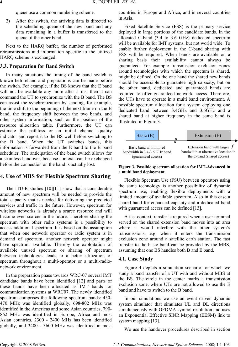 4 K. DOPPLER ET AL. Copyright © 2008 SciRes. I. J. Communications, Network and System Sciences. 2008; 1:1-103 queue use a common numbering scheme. 2) After the switch, the arriving data is directed to the scheduling queue of the new band and any data remaining in a buffer is transferred to the queue of the other band. Next to the HARQ buffer, the number of performed retransmissions and information specific to the utilized HARQ scheme is exchanged. 3.3. Preparation for Band Switch In many situations the timing of the band switch is known beforehand and preparations can be made before the switch. For example, if the BS knows that the E band will not be available any more after 5 ms, then it can command the UT to synchronize with the B band. The BS can assist the synchronization by sending, for example, the time shift to the beginning of the next frame on the B band, the frequency shift between the two bands, and other system information, such as the position of the resource allocation table. Furthermore, the UT can estimate the pathloss or an initial channel quality indicator and report it to the BS well before switching to the B band. When the UT switches bands, this information is forwarded from the E band to the B band scheduler. The anticipation of the band switch allows for a seamless handover, because contexts can be exchanged before the connection on the band is actually lost. 4. Use of MBS for Flexible Spectrum Sharing The ITU-R studies [10][11] show that a considerable amount of new spectrum will be needed to provide the total capacity that is needed for delivering the predicted services and traffic in the future. However, spectrum for wireless networks is already a scarce resource and will become even scarcer in the future. Therefore sharing the spectrum with other radio systems is a possibility to access additional spectrum. It is based on the assumption that when one network operator or radio system is in demand of spectrum, another network operator might have spectrum available. Thereby the exploitation of available unused spectrum or sharing of spectrum between technologies leads to a better utilization of spectrum throughout a multi-operator or a multi-radio- network environment. In the preparation phase towards WRC-07 several IMT candidate bands have been identified [12] and parts of these bands have been allocated as IMT bands for communication systems at WRC07. The newly identified spectrum comprises the following spectrum bands: 450- 470 MHz was identified globally, 698-802 MHz was identified in the Americas and some Asian countries, 790- 862 MHz was identified in Europe, Africa and most Asian countries, 2300 - 2400 MHz has been identified globally, and 3400 - 3600 MHz was identified in most countries in Europe and Africa, and in several countries in Asia. Fixed Satellite Service (FSS) is the primary service deployed in large portions of the candidate bands. In the allocated C-band (3.4 to 3.6 GHz) dedicated spectrum will be available for IMT systems, but not world wide. To enable further deployment in the C-band sharing with FSS will be required. When bands are available on a sharing basis their availability cannot always be guaranteed. For example transmission exclusion zones around technologies with which the spectum is shared, might be defined. On the one hand the shared new bands should be accessible to guarantee high capacity, but on the other hand, dedicated and guaranteed bands are required to offer guaranteed network access. Therefore, the UTs have to operate in a multi band environment. A possible spectrum allocation for a system deploying one dedicated band between 3.4GHz and 3.6GHz and a shared band at higher frequency in the same band is illustrated in Figure 3. Figure 3. Possible spectrum allocation for IMT-Advanced in a multi band deployment. Flexible Spectrum Use (FSU) between operators using the same technology is another possibility of dynamic spectrum use, enabling flexible deployments with a limited amount of available spectrum. Also in this case a shared band for enhanced capacity and a dedicated band with guaranteed access can be defined [13]. A fast context transfer is required when a user terminal served on the shared extension band moves into an area where it would interfere with the other system’s transmissions, e.g. when it enters the transmission exclusion zone around a satellite earth station. The fast transfer to the basic band can be provided by the MBS, assuming that one BS handles both B and E band. 4.1. Case Study Figure 4 depicts a simulation scenario for which we study a band transfer of a UT with and without MBS at the BS. The circle in the center marks a transmission exclusion zone, where UTs are not allowed to use the E band and have to switch to the B band. In our simulations we use an event driven dynamic system simulator that simulates UL and DL directions simultaneously with OFDMA symbol resolution and uses an Exponential Effective SINR Mapping (EESM) link to system mapping [13]. We use the handover procedures described in section f Basic band with limited bandwidth in 3.4-3.6 GHz band (guaranteed access) Extension band with larger bandwidth at alternative location in the C-band (shared access) Basic ( B ) Extension ( E ) 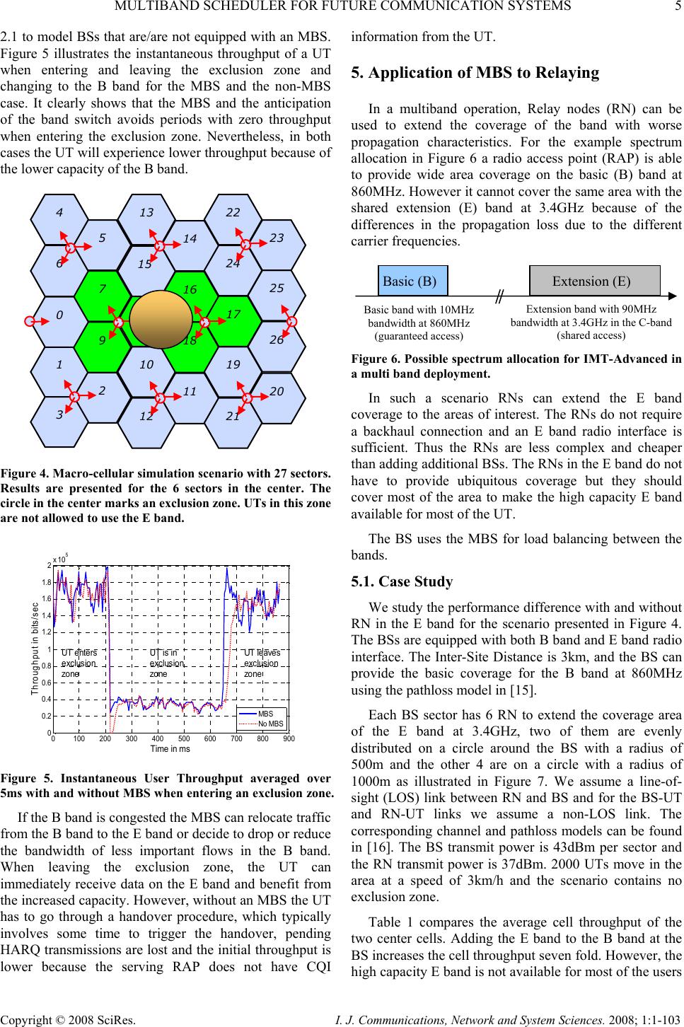 MULTIBAND SCHEDULER FOR FUTURE COMMUNICATION SYSTEMS 5 Copyright © 2008 SciRes. I. J. Communications, Network and System Sciences. 2008; 1:1-103 2.1 to model BSs that are/are not equipped with an MBS. Figure 5 illustrates the instantaneous throughput of a UT when entering and leaving the exclusion zone and changing to the B band for the MBS and the non-MBS case. It clearly shows that the MBS and the anticipation of the band switch avoids periods with zero throughput when entering the exclusion zone. Nevertheless, in both cases the UT will experience lower throughput because of the lower capacity of the B band. Figure 4. Macro-cellular simulation scenario with 27 sectors. Results are presented for the 6 sectors in the center. The circle in the center marks an exclusion zone. UTs in this zone are not allowed to use the E band. 0100 200 300 400500 600 700 800 900 0 0.2 0.4 0.6 0.8 1 1.2 1.4 1.6 1.8 2x 10 5 Time in ms Throughput in bits/sec MBS No MBS UT enters exclusion zone UT is in exclusion zo ne UT leaves exclusion zo ne Figure 5. Instantaneous User Throughput averaged over 5ms with and without MBS when entering an exclusion zone. If the B band is congested the MBS can relocate traffic from the B band to the E band or decide to drop or reduce the bandwidth of less important flows in the B band. When leaving the exclusion zone, the UT can immediately receive data on the E band and benefit from the increased capacity. However, without an MBS the UT has to go through a handover procedure, which typically involves some time to trigger the handover, pending HARQ transmissions are lost and the initial throughput is lower because the serving RAP does not have CQI information from the UT. 5. Application of MBS to Relaying In a multiband operation, Relay nodes (RN) can be used to extend the coverage of the band with worse propagation characteristics. For the example spectrum allocation in Figure 6 a radio access point (RAP) is able to provide wide area coverage on the basic (B) band at 860MHz. However it cannot cover the same area with the shared extension (E) band at 3.4GHz because of the differences in the propagation loss due to the different carrier frequencies. Figure 6. Possible spectrum allocation for IMT-Advanced in a multi band deployment. In such a scenario RNs can extend the E band coverage to the areas of interest. The RNs do not require a backhaul connection and an E band radio interface is sufficient. Thus the RNs are less complex and cheaper than adding additional BSs. The RNs in the E band do not have to provide ubiquitous coverage but they should cover most of the area to make the high capacity E band available for most of the UT. The BS uses the MBS for load balancing between the bands. 5.1. Case Study We study the performance difference with and without RN in the E band for the scenario presented in Figure 4. The BSs are equipped with both B band and E band radio interface. The Inter-Site Distance is 3km, and the BS can provide the basic coverage for the B band at 860MHz using the pathloss model in [15]. Each BS sector has 6 RN to extend the coverage area of the E band at 3.4GHz, two of them are evenly distributed on a circle around the BS with a radius of 500m and the other 4 are on a circle with a radius of 1000m as illustrated in Figure 7. We assume a line-of- sight (LOS) link between RN and BS and for the BS-UT and RN-UT links we assume a non-LOS link. The corresponding channel and pathloss models can be found in [16]. The BS transmit power is 43dBm per sector and the RN transmit power is 37dBm. 2000 UTs move in the area at a speed of 3km/h and the scenario contains no exclusion zone. Table 1 compares the average cell throughput of the two center cells. Adding the E band to the B band at the BS increases the cell throughput seven fold. However, the high capacity E band is not available for most of the users 10 11 18 19 20 26 22 25 21 13 14 12 1 2 9 16 17 7 6 8 15 23 0 3 24 5 4 Extension band with 90MHz bandwidth at 3.4GHz in the C-band (shared access) Extension ( E ) Basic ( B ) Basic band with 10MHz bandwidth at 860MHz (guaranteed access)  6 K. DOPPLER ET AL. Copyright © 2008 SciRes. I. J. Communications, Network and System Sciences. 2008; 1:1-103 in the cell and the increase does not fully scale with the increase in bandwidth. When using RNs to extend the E band coverage the throughput almost doubles. Further, the high capacity E band is available to most of the users in the cell. Table 1. Cell throughput comparison with/without E band and RN. Scenario Average cell throughput [Mbps] Only B band BS 22 BS with both bands 150 BS with both bands and RN with E band 270 For quality-of-service support the BS has to take additional criteria into account in the presence of relays, when deciding which data packets should be sent on the basic band and which packets on the extension band: • Services with low delay requirements should be scheduled on the band/link that requires fewer hops (this will mainly be the B band as it has the better propagation conditions and therefore a wider coverage area). • High speed users with an E band served by RNs should be transferred to the basic band (RN will have smaller coverage area and this policy will reduce the number of missed packets, because the UT has left the coverage area of the RN). Figure 7. Each sector of Figure 4 is augmented with 6 RN. The BSs transmit on both B band and E band, whereas the RNs only transmit on the E band. 5.2. Relays with MBS So far we have presented the multi-band operation in RECs for RNs that operate only in the E band. However some of the RNs might be equipped with both a B band and an E band radio interface. Figure 8 illustrates the case where the RN closest to the BS is equipped with an MBS and therefore packets that should be transmitted on the B band to the UT by the RN can be received on the E band. Typically the E band offers higher capacity than the B band. Thus, it is beneficial to use the E band on the BS-RN link, even if the RN serves the UT on the B band. Here the MBS allows balancing the load of the two bands on the link between the BS and the RN. To investigate the potential benefits of RNs equipped with an MBS and a B band radio interface for the spectrum allocation in Figure 6 we study the coverage for indoor users in the scenario presented in Figure 9. Each BS is equipped with two sectors and they form together with 3 RN in the same street a REC. The sectors to the right and down have 2 RNs wheras the RN closer to the BS is equipped with an MBS. The other RNs have only an E band radio interface. Figure 8. Relay enhanced cell with B band at lower frequency and E band at higher frequency. BS/RN with MBS can decide on which band to transmit packets. RN without MBS receive and forward packets only on extension band. Figure 9. Relay based deployment in the Manhattan grid. The closest RN right of the BS in horizontal streets and down from the BS in vertical streets is equipped with a B and E band radio interface and an MBS. Table 2 compares the coverage area of the different bands for this scenario. The coverage area has been R N R N R N R N R N R N  MULTIBAND SCHEDULER FOR FUTURE COMMUNICATION SYSTEMS 7 Copyright © 2008 SciRes. I. J. Communications, Network and System Sciences. 2008; 1:1-103 calculated using the pathloss models in [16]. In particular we applied the B1 LOS model for points in the same street than the RAP (BS or RN) and the B1 NLOS model for points in different streets. Inside the building blocks we use the B4 outdoor-to-indoor model, whereas we assume an indoor pathloss of 0.5dB/m for the E band (as specified by the model) and 0.3dB/m for the B band to take into account the lower indoor propagation losses at 860MHz than at 3.4GHz. In both cases the BS and RN use a transmit power of 30dBm and the BS is equipped with a 120 degree sector antenna having 11dBi antenna gain, whereas the RN is equipped with an omni- directional antenna and an antenna gain of 7dBi, following the assumptions in [17]. Table 2. Area with a spectral efficiency higher than 1bps/Hz. E-band 60% B band without RN 68% B band with RN 83% Figure 10. Coverage of B band with BS and part of the RN having an B band interface. Figure 11. Coverage of the B band with only BS having a B band interface. The E band can only provide a spectral efficiency of more than 1b/s/Hz in 60% of the area even though every RAP is equipped with an E band interface. In contrary, the BS alone can already provide this spectral efficiency for the same area on the B band. The coverage area can be further increased to 83% by equipping one third of the RNs with a B band interface. The coverage for the B band in the center area of the scenario in Figure 9 is illustrated in Figure 10 and Figure 11 for the case when only BS have a B band radio interface and for the case where additionally one third of the RNs are equipped with a B band radio interface, respectively. This comparison clearly shows that the B band should be available at the RN as well to provide coverage. However, due to the lower bandwidth of the B band, the B band should only be used to serve UT that cannot be served on the E band but not for forwarding data to the RN. Therefore, the RN should be equipped with an MBS to be able to receive data on the E band and forward it on the B band to UTs that it serves on the B band. On the other hand, for relay deployments with more than two hops the BS might be able to reach RNs via one hop on the B band and via multiple hops on the E band. In this case, it will be beneficial for delay sensitive traffic to send data on the B band to the RN, which forwards it then to the UT. 5.3. ARQ in relay network with MBS Another important aspect of a REC is the handling of the outer ARQ (E2E ARQ) between BS and UT, sometimes also referred to as relay ARQ [8]. Without an outer ARQ between BS and UT, the BS does not know whether data sent to the RN is successfully transmitted to the UTs. Thus, in case of handovers, data that is still in the buffer of RNs might be lost, even if the handover destination is within the REC. Additionally, an outer ARQ (E2E ARQ) process is used on each hop to recover from residual inner ARQ (HARQ) errors, caused for example by a NACK that is misinterpreted as an ACK. A detailed description of the ARQ handling in RECs can be found in [8]. For relay deployments with more than two hops, an MBS offers additional degrees of freedom. Even though the BS initiates a handover to a RN in the E band, the BS or another RN with MBS might still be able to serve the UT on the B Band. In this case, outer ARQ retransmissions of delay sensitive traffic can be performed on the B band by these nodes. 5.4. MBS and cooperative relaying Next to single path relaying, cooperative relaying can be integrated as an add-on to single path relaying as proposed for example in [8]. A receiving node combines signals from more than one transmitting node. Cooperative relaying and intelligent deployment reduce  8 K. DOPPLER ET AL. Copyright © 2008 SciRes. I. J. Communications, Network and System Sciences. 2008; 1:1-103 the total cost of a multi-hop network by reducing the number of relays needed for a given performance [8]. Thus, it is important to show, that the MBS concept fits well with cooperative relaying. In particular we discuss it using the cooperative relaying concept in [8]. Multi-hop diversity is one example, in which a receiving node combines the signals received from previous nodes in the path. In a 2-hop DL path, the UT combines the signal from a RN with the signal from the BS that can be received on different resources. MIMO cooperative relaying is another example, where the BS first transmits the data to be forwarded in a cooperative transmission to the RN. Then the BS and the RN antennas form a virtual antenna array and perform a joint MIMO transmission on the same resources. In both cases the BS allocates the resources for all the cooperative transmissions, i.e. even in a case where the RN is equipped with an MBS, the BS also decides on which band and resources the cooperative transmissions will take place. For the multi-hop diversity case, cooperative transmissions could in principle be scheduled on two different bands requiring the UT to be associated with two bands at the same time which increases the UT complexity and power consumption. Thus, cooperative transmissions on different bands should be avoided and the BS has to balance the gain from utilizing cooperative relaying and from using different bands on the first and second hop. However, as described above, by using the HARQ context transfer, retransmissions can be performed on another band and additional diversity gain can be obtained without requiring the UT to operate simultaneously on two bands. This is not an issue in the MIMO cooperative relaying case, where the BS can send for example data on the E band and then perform a joint MIMO transmission on the B band, whereas the UT only receives on the B band. 6. Conclusion A new concept called Multi-Band Scheduler (MBS) for future communication systems was introduced. This scheduler allows for operation on multiple bands in a delay constrained environment. The proposed tight integration between multiple bands enables a fast and seamless switch between different bands. The Multi-Band scheduler also ensures that the PHY and MAC layer operation is abstracted from the higher layers. This means that the higher layers are not aware of the actual resources used, but only of the available capacity. The fast switch between multiple bands adds additional degrees of freedom for optimizing the network operation. Moreover, the MBS can be utilized to efficiently balance the load of the bands in the network or to provide required quality of service levels to the UTs. The operation of the MBS was discussed in detail for two scenarios: Spectrum sharing and relays. The spectrum sharing case comprises a multiband operation with a smaller band dedicated to the communication system and an extension band that is shared with another system but offers higher capacity. In this scenario the MBS can be applied in two ways, on the one hand the MBS enables simultaneous access to a guaranteed basic band and the band shared with another technology. On the other hand the MBS can be used for sharing spectrum between different operators of the same technology where a part of the band is dedicated to each operator and the rest of the band is shared between the operators. Our simulation results show that using the MBS, a seamless switch can be made if the shared band is no longer available. The relay case illustrates a scenario with different propagation properties and thus different coverage area of the used bands. In this scenario RNs are used to extend the coverage of the high capacity extension band that has a higher propagation loss than the basic band. Our simulation results show that RNs are an effective way to balance the coverage of the bands. Thereby they greatly increase the overall capacity of the network and the high capacity band is available to most of the user terminals. Further, the MBS at both the BS and the RN enables to balance the network load on each hop by utilizing different bands. 7. Acknowledgement The authors would like to thank Kennett Aschan for his valuable support and fruitful discussions during the preparation of this article. 8. References [1] Recommendation ITU-R M.1645, “Framework and overall objectives of the future development of IMT- 2000 and systems beyond IMT-2000”, 2003. [2] K. Hooli, S. Thilakawardana, J. Lara, J-P. Kermoal, S. Pfletschinger, “Flexible Spectrum Use between WINNER Radio Access networks”, IST Mobile Summit, Greece, June 2006. [3] K. Doppler, He Xiaoben, C. Wijting, A. Sorri, “Adaptive Soft Reuse for Relay Enhanced Cells”, IEEE Vehicular Technology Conference 2007 spring, April 2007, pp 758-762. [4] https://www.ist-winner.org [5] M. Sternard, T. Svensson, G. Klang, “The WINNER B3G System MAC Concept”, IEEE Vehicular Technology Conference 2006 fall, Sept 2006. [6] IST-WINNER II, “D6.11.2 Key Scenarios and  MULTIBAND SCHEDULER FOR FUTURE COMMUNICATION SYSTEMS 9 Copyright © 2008 SciRes. I. J. Communications, Network and System Sciences. 2008; 1:1-103 Implications for WINNER II”, Sept. 2006, available at https://www.ist-winner.org/deliverables.html [7] 3GPP TR 25.913 V7.3.0 (2006-03) Requirements for Evolved UTRA (E-UTRA) (Release 7). [8] IST-WINNER II, “D3.5.2 Assessment of relay based deployment concepts and detailed description of multi-hop capable RAN protocols as input for the concept group work”, June 2007, available at https://www.ist-winner.org/deliverables.html [9] K. Doppler, C. Wijting, J-P. Kermoal, “Multi-Band Scheduler for Future Communication Systems”, WiCom 2007, P.R: China, Sept. 2007, pp 6738-6742. [10] Recommendation ITU-R M.1768, “Methodology for calculation of spectrum requirements for the future development of the terrestrial component of IMT- 2000 and systems beyond IMT-2000”, 2006. [11] Report ITU-R M.2078, “Spectrum requirements for the future development of IMT-2000 and IMT- Advanced”, 2006. [12] Report ITU-R M.2079, “Technical and operational information for identifying spectrum for the terrestrial component of future development of IMT- 2000 and IMT-Advanced”, 2006. [13] M. Bennis, J. -P. Kermoal, P. Ojanen, J. Lara, S. Abedi, R. Pintenet, S. Thilakawardana and R. Tafazolli, “Advanced spectrum functionalities for 4G WINNER radio network”, Wireless Personal Communications journal, Springer 2007 (accepted for publication). [14] K. Brueninghaus, D. Astely, T. Saelzer, et al. “Link performance models for system level simulations for broadband radio access systems”, Proceedings of the PIMRC 2005, Berlin, September 2005 [15] “Universal Mobile Telecommunications System (UMTS); Selection procedures for the choice of radio transmission technologies of the UMTS”, TR 101 112 v3.2.0 (1997-11), UMTS30.03 [16] IST WINNER II “D1.1.2 WINNER II Channel Models Part I Channel Models”, September 2007 available at https://www.ist-winner.org/deliverables. html [17] IST WINNER II “D6.13.11 Final CG “metropolitan area” description for integration into overall System Concept and assessment of key technologies”, October 2007 available at https://www.ist-winner.org/ deliverables.html |