Journal of Electromagnetic Analysis and Applications
Vol.09 No.02(2017), Article ID:73963,13 pages
10.4236/jemaa.2017.92002
Compact UWB Power Divider, Analysis and Design
Osama Dardeer1, Tamer Abouelnaga1*, Ashraf Mohra2, Hadia Elhennawy3
1Department of Microstrip Circuits, Electronics Research Institute, Giza, Egypt
2Faculty of Engineering, Benha University, Qalyubia, Egypt
3Faculty of Engineering, Ain Shams University, Cairo, Egypt

Copyright © 2017 by authors and Scientific Research Publishing Inc.
This work is licensed under the Creative Commons Attribution International License (CC BY 4.0).
http://creativecommons.org/licenses/by/4.0/


Received: January 3, 2017; Accepted: February 3, 2017; Published: February 7, 2017
ABSTRACT
In this paper, two ultra-wide band power dividers are introduced. Compact equal power divider is considered firstly where an extended transmission lines and double open stubs are used in order to increase the bandwidth. Secondly, an unequal UWB power divider is introduced where multi-stage impedance is used. The proposed power dividers are fabricated and measured. The overall sizes of the proposed power dividers are 11.37 × 17.87 mm2 for the equal one and 12.13 × 29.03 mm2 for the unequal power divider. The simulated results are compared with the measured results and good agreement is obtained.
Keywords:
Ultra-Wideband, Wilkinson Power Divider, Double Stubs, Unequal Power Divider

1. Introduction
Power dividers play an important role in many microwave systems such as balanced mixers, phase shifters, power amplifiers, and antenna array feed networks. Wilkinson power dividers are the most popular dividers which achieve completely matched output ports with high isolation between them and a fractional bandwidth of 20%. There is a great interest in designing ultra-wideband (UWB) components due to the rapid growth of the short range broadband communications, indoor wireless networks, and UWB radar imaging systems. Different UWB power dividers had been designed [1] [2] [3] [4] in order to achieve that goal. A tapered slot and a fan-shaped slot were introduced into the circuit design to improve the performance of the UWB non-coplanar power divider [2] . A compact UWB power divider based on microstrip-to-slotline transition was introduced in [3] .
In [5] , a single open circuited radial stub was introduced at each of the Wilkinson power divider output port to broaden the bandwidth. The power divider presented in [6] was based on signal interference technique where the short ended symmetrical coupled line and transversal transmission line were introduced at both output ports of the divider. A high isolation was achieved between output ports due to the microstrip-to-slotline transitions [7] . Also, for bandwidth enhancement purpose, a short ended stub was combined with an open ended microstrip line in the power divider structure, as stated in [8] . In [9] [10] , the proposed UWB power divider with notched band was based on square ring multiple mode resonator.
In this paper, an UWB equal power divider is analyzed and proposed. The analysis is based on the idea of double stub matching. It includes an extended transmission line and double open circuited stubs at each of the output ports in order to increase the bandwidth of operation. Also, an unequal UWB power divider analysis based on the idea of two section transmission line is proposed. On contrary to the unequal power dividers presented in [11] [12] [13] , the proposed design is simple and efficient because it can be viewed as two section quarter wave transformer.
2. Equal Power Divider Analysis and Design
Figure 1 shows the schematic diagram of the proposed UWB power divider. In order to broaden the bandwidth, extended transmission line and open circuited stubs have been added [1] . The extended transmission line has the same characteristic impedance as the main line but with different electrical length θ3. The double open stubs  and
and  are used to introduce multiple transmission poles through the whole UWB frequency range. Adjusting the

Figure 1. The proposed UWB power divider using extended transmission line and open circuited stubs.
open stubs lengths can shift the suppressed harmonics outside the UWB range [14] . By tuning the length of the extended line , a better impedance matching can be achieved for input and output ports over wide frequency band.
In order to analyze the proposed equal power divider in simple and efficient manner, it can be represented by a cascade connection of five two-port networks using ABCD matrices and even-odd mode analyses. In the even mode, Figure 2, the isolation resistance can be neglected. By substitution of Z3 with  and considering the
  distance, the A B C D matrix will be:
 (1)
(1)
Similarly, for the odd mode case, Figure 3, the symmetry plane is across the isolation resistance. The admittance of the 6thstage will have a value of . The A B C D matrix will be:
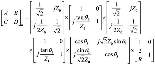 (2)
(2)
The calculated A B C D parameters are converted to S-parameters [15] . The S-parameters are the scattering parameters that relate between the reflected to incident or transmitted to incident. The proposed power divider is symmetric in structure, so it can be analyzed by the even-odd decomposition method. For 3

Figure 2. Even mode equivalent circuit of the proposed power divider.

Figure 3. Odd mode equivalent circuit of the proposed power divider.
dB equal power divider, the characteristic impedance of the input and output ports are . The isolation resistor R is selected to be
  and the characteristic impedance of the
  transmission line is chosen to be
 .
.
In the case where two signals of the same magnitude and phase (even mode signals) are applied to ports 2 and 3 of the circuit shown in Figure 1, the plane of symmetry is a magnetic wall, open circuit case, so the isolation resistor R can be eliminated. Accordingly, the circuit can be bisected into the one shown in Figure 2 for even mode analysis. For arbitrary electrical lengths for the extended transmission line θ3 and the two open circuited shunt stubs θ1 and θ2 in addition to their impedances Z1 and Z2, the A B C D parameters are obtained using Equation (1) as:
 (3)
(3)
 (4)
(4)
 (5)
(5)
 (6)
(6)
In the case where two signals of the same magnitude but out of phase (180˚ phase shift), such case is known as an odd mode, when such two signals are applied to ports 2 and 3 of the circuit shown in Figure 1, the plane of symmetry is an electric wall, which is known as short circuit case. Accordingly, the circuit can be bisected to the one shown in Figure 3 for odd mode analysis. For arbitrary electrical lengths for the extended transmission line θ3 and the two open circuited shunt stubs θ1 and θ2 in addition to their impedances Z1 and Z2, the A B C D parameters are obtained using Equation (2) as:
 (7)
(7)
 (8)
(8)
 (9)
(9)
 (10)
(10)
Low cost FR4 material with dielectric constant , thickness h = 0.8 mm, and loss tangent
  is used as substrate for the proposed equal power divider. The overall size of the proposed power divider is 11.37 × 17.87 mm2. The flowchart for illustrating the analysis and simulation trials until the optimized parameters are obtained is shown in Figure 4. The optimized parameters of the proposed power divider are listed in Table 1.
The layout of the proposed UWB power divider is presented in Figure 5, where it is done by using extended transmission lines and two open stubs with cascaded impedances. The s-parameters of the proposed UWB power divider calculated from the analysis mentioned above has been verified using CST full wave analysis simulator and a good agreement is obtained. The S-parameters

Figure 4. The flowchart for the S-parameters optimization process.

Table 1. Optimized dimensions of the proposed power divider.
results are illustrated in Figure 6. The CST includes modules based on numerous different methods including finite element method (FEM), method of moments (MoM), multilevel fast multipole method (MLFMM) and shooting boundary ray (SBR), each offering distinct advantages in their own domains. CST is basically a full wave equation numerical solution based on iterations; while the analytical solution is based on quasi transverse electromagnetic (TEM)
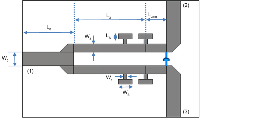
Figure 5. Layout of the proposed UWB divider with equal power division by using extended transmission lines and two open stubs with cascaded impedances.
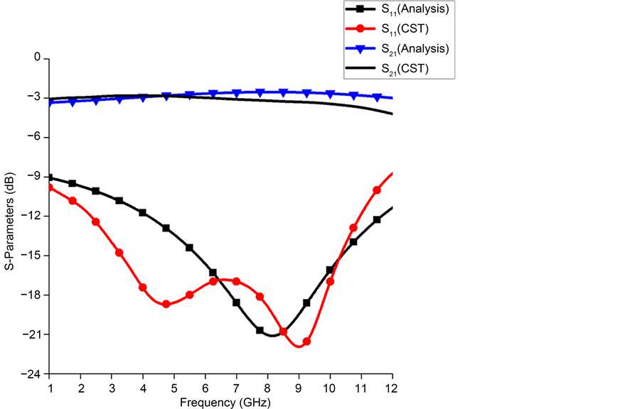
Figure 6. Proposed power divider s-parameters, analytically and by CST.
solution of the full wave equation, so some discrepancy must be appearing between analytical and simulation results. The dimensions of the proposed power divider were optimized to obtain good return loss and good isolation between output ports over the UWB frequency range.
3. Unequal Power Divider Analysis and Design
Figure 7 shows the schematic diagram of the proposed unequal UWB power divider. This design incorporates an input quarter wave transformer with

Figure 7. Schematic diagram for the proposed unequal UWB power divider.
characteristic impedance  in order to adjust the input reflection coefficient. The unequal division ratio is achieved by adjusting the impedance ratio of the output arms (Z2 and Z3). The output quarter wave transformers with characteristic impedances
  and
and  are added to transform Z2 and Z3 into the impedance Zc.
This design can be viewed as a two section quarter wave transformer. By this way, this design will achieve a significant increase in the performance. According to [16] , the characteristic impedance of each transmission line can be calculated as follows:
 (11)
(11)
 (12)
(12)
 (13)
(13)
 (14)
(14)
where  denotes the power dividing ratio of port 3 to 2, and Zc is the characteristic port impedance which is equal to
 . The layout of the proposed unequal UWB power divider is shown in Figure 8. Same low cost FR4 substrate has been used. The overall size of the proposed unequal UWB power divider is 12.13 ´ 29.03 mm2. For example, if it is required to design unequal power divider with division ratio, S31 = 0.7962 or −1.98 dB and S21 = 0.6046 or −4.37 dB, then the power dividing ratio (k) is equal to 1.3168. By substituting into Equations (11)-(14), the values of the characteristic impedances for the power divider are as follows,
  ,
,  ,
,  ,
,  and
and . After extensive simulation trials, the optimized parameters of the proposed power divider are as follows:
 , Z2 = 75 Ω, Z3 = 35 Ω,
  , L0 = 5 mm, L1 = 7.88 mm, L2 = 6.19 mm, L3 = 5.83 mm, L4 = 6.09 mm, and L5 = 5.91 mm. The calculated S-parameters from the above discussion have been presented in Figure 9. The simulated transmission values are S31 = 0.7691 or −2.28 dB and S21 = 0.5158 or −5.75 dB.
4. Fabrication and Measurement
Finally, the proposed UWB equal power divider is fabricated and measured with a vector network analyzer. Figure 10 shows the photos of the fabricated UWB equal power divider, where their sizes are compact. Figure 11 and Figure 12 demonstrate the comparison between the simulated and measured results. From Figure 11, it can be seen that the input reflection coefficient is below −10 dB from 1 GHz up to 12 GHz; which cover the entire region for The UWB range (3.1 - 10.6 GHz). Form Figure 12, the coupling coefficient S21 and S31 are around (−3 dB ± 1) overall the UWB range.
On the same manner, the designed UWB unequal power divider is fabricated and its photo is shown in Figure 13; while the divider has a small size. The S-parameters for the simulated and measured power divider are shown in Figure 14 and Figure 15. The return loss S11 for simulation and measurement
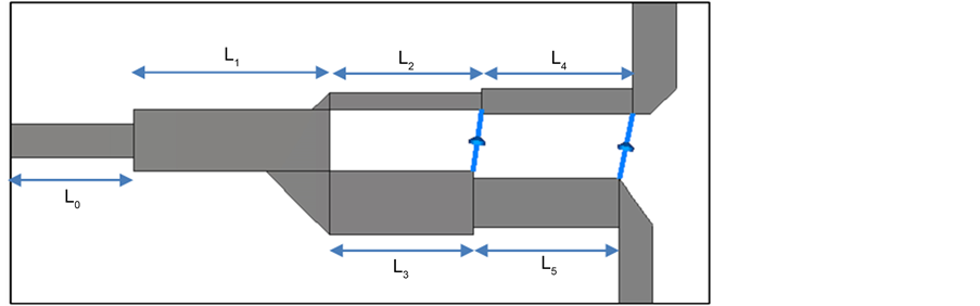
Figure 8. Proposed unequal UWB power divider layout.

Figure 9. Simulated results of the proposed unequal UWB power divider.

 (a) (b)
Figure 10. Photograph of the fabricated equal UWB power divider.

Figure 11. Simulated and measured return loss of the proposed UWB equal power divider.
is less than −10 dB over the band 2.5 GHz to 10.8 GHz; that cover the UWB rang. The insertion loss S21 is around −3.0 ± 0.8 dB over the bandwidth 3.0 GHz to 9 GHz which cover most of the UWB range. The insertion loss S31 is around −5.0 ± 1.5 dB over the bandwidth 3.0 GHz to 8 GHz which cover also most of the UWB range.
The deviations of the measurements from the simulations came from tolerance in fabrications; mismatch due to soldering of launchers and due to the losses of FR4 substrate material especially at higher frequency above 6 GHz.

Figure 12. Simulated and measured insertion loss (S21, S31) of the proposed UWB equal power divider.

 (a) (b)
Figure 13. Photograph of the fabricated unequal UWB power divider.

Figure 14. Simulated and measured return loss of the proposed UWB unequal power divider.

Figure 15. Simulated and measured insertion loss of the proposed UWB unequal power divider.
5. Conclusion
In this work, an UWB equal power divider based on double stub matching was proposed. The UWB performance was achieved by introducing an extended transmission line and double open circuited stubs to each of the output ports of the Wilkinson power divider. The proposed divider was investigated by using even and odd mode analysis. In addition, the UWB power divider with unequal power ratio was presented. There was a good agreement between simulated and measured results. Simple structure and compact size characteristics of the proposed dividers make them very useful in UWB applications and antenna array feed networks.
Cite this paper
Dardeer, O., Abouelnaga, T., Mohra, A. and Elhennawy, H. (2017) Compact UWB Power Divider, Analysis and Design. Journal of Electromagnetic Analysis and Applications, 9, 9- 21. https://doi.org/10.4236/jemaa.2017.92002
References
- 1. Deng, P.H., Guo, J.H. and Kuo, W.C. (2012) New Wilkinson Power Dividers Based on Compact Stepped-Impedance Transmission Lines and Shunt Open Stubs. Progress in Electromagnetics Research, 123, 407-426.
https://doi.org/10.2528/PIER11111612 - 2. Peng, H., Yang, Z., Liu, Y., Yang, T. and Tan, K. (2013) An Improved UWB Non-Coplanar Power Divider. Progress in Electromagnetics Research, 138, 31-39.
https://doi.org/10.2528/PIER13011003 - 3. Xiao, L., Peng, H. and Yang, T. (2014) The Design of a Novel Compact Ultra-Wideband (UWB) Power Divider. Progress in Electromagnetics Research Letters, 44, 43-46.
https://doi.org/10.2528/PIERL13111205 - 4. Alshamaileh, K.A., Almalkawi, M.J., Junuthula, R.R., Devabhaktuni, V.K. and Aaen, P.H. (2015) ANN-Based Modeling of Compact Impedance-Varying Transmission Lines With Applications to Ultra-Wideband Wilkinson Power Dividers. International Journal of RF and Microwave Computer-Aided Engineering, 25, 563-572.
https://doi.org/10.1002/mmce.20893 - 5. Ahmed, O. and Sebak, A.R. (2009) A Modified Wilkinson Power Divider/Combiner for Ultra Wideband Communications. IEEE Antennas and Propagation Society International Symposium, June 2009, 1-4.
- 6. Zhuge, C., Song, K. and Fan, Y. (2012) Ultra-Wideband (UWB) Power Divider Based on Signal Interference Techniques. Microwave and Optical Technology Letters, 54, 1028-1030.
https://doi.org/10.1002/mop.26745 - 7. Xiao, L. and Yang, T. (2014) UWB Multilayer Power Divider with High Isolation. Progress in Electromagnetics Research C, 50, 57-63.
https://doi.org/10.2528/PIERC14031501 - 8. Yang, Z., Luo, B., Dong, J. and Yang, T. (2016) Ultra-Wideband Power Divider Employing Coupled Line and ShortEndedStub. Microwave and Optical Technology Letters, 58, 713-715.
https://doi.org/10.1002/mop.29652 - 9. Weng, M., Song, Y. and Zhao, J. (2015) Design of Compact Microstrip UWB Power Divider Using Square Ring Multiple-Mode Resonator. IEEE Asia-Pacific Microwave Conference (APMC), December 2015, 1-3.
https://doi.org/10.1109/apmc.2015.7411703 - 10. Wu, J.Y., Du, M., Peng, H., Wang, X. and Ling, Y. (2016) A New Printed Microstrip UWB Power Divider with Notched Band. Progress in Electromagnetics Research C, 62, 71-76.
https://doi.org/10.2528/PIERC15120306 - 11. Zhu, Y.Z., Zhu, W.H., Zhang, X.J., Jiang, M. and Fang, G.Y. (2010) Shunt-Stub Wilkinson Power Divider for Unequal Distribution Ratio. IET Microwaves, Antennas &Propagation, 4, 334-341.
https://doi.org/10.1049/iet-map.2008.0440 - 12. Wu, Y. and Liu, Y. (2013) Compact 3-11 GHz UWB Planar Unequal Power Divider Using Two-Section Asymmetric Coupled Transmission Lines and Non-Uniform Microstrip. Electronics Letters, 49, 1002-1003.
https://doi.org/10.1049/el.2013.0296 - 13. Wei, F., Shi, X.W., Qin, P.Y. and Guo, Y.J. (2014) Compact UWB Power Divider with Unequal Distribution Ratio. IEEE International Workshop on Antenna Technology (IWAT), March 2014, 297-299.
https://doi.org/10.1109/iwat.2014.6958669 - 14. Kim, M.G., Kim, J.S. and Mittra, R. (2012) Modified Wilkinson Power Divider for Suppression of nth Harmonics. Electronics Letters, 48, 1540-1542.
https://doi.org/10.1049/el.2012.3423 - 15. Pozar, D.M. (2012) Microwave Engineering. John Wiley & Sons, New Jersey.
- 16. Collin, R.E. (2007) Foundations for Microwave Engineering. John Wiley & Sons, New Jersey.