Journal of Electromagnetic Analysis and Applications
Vol.4 No.2(2012), Article ID:17667,7 pages DOI:10.4236/jemaa.2012.42007
Periodic Modulation of Nonlinearity in a Fiber Bragg Grating: A Numerical Investigation
![]()
1Teleinformatics Engineering Department, Federal University of Ceará, Fortaleza-Ce, Brazil; 2Telecommunications and Materials Science and Engineering Laboratory (LOCEM), Campus do Pici, Fortaleza-CE, Brazil; 3Department of Infrastructure, Telecommunications Systems Specialist Laboratory and Teaching, East, Federal Institute of Ceará, Fortaleza Campus, Fortaleza, Brazil.
Email: sombra@ufc.br
Received November 23rd, 2011; revised December 26th, 2011; accepted January 4th, 2012
Keywords: Bragg Gratings; Nonlinearity Modulation; Optical Bistability; Nonlinear Switching
ABSTRACT
We present numerical studies on the switching characteristics of a fiber Bragg grating (FBG) with modulation in the third order nonlinear index of refraction along it’s length. The FBG is operating in a continuous wave regime (CW). This study was done taking into account the possible asymmetry brought by the non harmonic modulation of the nonlinearity, leading to different reflection and transmission characteristics, that depend on the direction of propagation along the modulated nonlinear FBG. This phenomenon may be useful for applications like an optical isolator. It was found that for a set of values of the modulation parameter, the FBG can exhibit multistable states. The numerical studies were obtained starting from the coupled-mode equations solved from the coupled-mode theory and simulated using the fourth-order Runge-Kutta method.
1. Introduction
Fiber Bragg gratings (FBG) are used for several purposes: in sensor applications and optical communications, like optical wavelength-division-multiplexer (WDM) systems, dispersion compensation schemes and nonlinear switching [1]. The presence of nonlinear effects (XPM and SPM) affects deeply the transmission and reflection characteristics, leading to the existence of bistability [2]. Bistability is a fundamental phenomenon for nonlinear switching in nonlinear fiber Bragg gratings (NLFBG). It arises when there are matching conditions between the coupling functions, detuning from Bragg resonance and nonlinearity. Although the properties of uniform and nonuniform FBG are well known, the NLFBG, as proposed in this paper, can be implemented in optical systems as a nonlinear switching device or as a filter with high efficiency. Periodically modulation of a NLFBG has also been proposed early, but it was never been studied widespread yet [3]. For dense WDM (DWDM) is necessary to have extreme high rejection of the non-resonant light in order to eliminate the crosstalk between information channels [4]. For applications such as add-drop filters, is important that the grating response to be less than –30 dB from the maximum reflection. Because of these requirements the study of nonlinear apodized gratings was included in this paper. We also present numerical studies of the reflection, transmission and all-optical switching characteristics from the modulated nonlinear FBG’s obtained from computational simulations.
2. Theory
2.1. Coupled-Mode Equations
Assume a L length low loss fiber which the linear refractive index can be written as:
 (1)
(1)
where  and
and  is the grating propagation constant related with the grating modulation period by
 . Including an intensity-dependent refractive index term, so that the polarization density due to a single monochromatic beam of field strength E is:
 (2)
(2)
where n2(z) is the nonlinear index function. Assuming that the periodic variation of n2(z) along the grating can be written as:
 (3)
(3)
where  is the nonlinear modulation amplitude, N is a number of harmonic signification and φ is a phase constant. Note that when N and φ match the symmetry condition,
  where the FBG is symmetric from both sides of the fiber, so called uniform NLFBG (with j integer and
  is the nonlinear modulation wave number). Furthermore, for
  and N is an odd integer, the grating is symmetric. Near the Bragg resonance frequency, we can write the electrical field as a sum of the propagating and counter-propagateing waves:
 (4)
(4)
where β = n0ω/c is the propagation constant,  and
and  and
and  are the forward and backward waves. Using 3 - 4 in Maxwell equations, and using the slow varying envelope approximation [5], we find
 (5)
(5)
 (6)
(6)
with nonlinear coupling function explicitly written as:
 (7)
(7)
where in (5) and (6) denotes the total derivative ,
,  is the nonlinear parameter modulation amplitude
 , is the parameter related to the detuning from the Bragg frequency and
  is the coupling function. The boundary conditions for Equations (5) and (6) are F(0) = F0 and B(L*) = 0, where F0 is the input electrical field in NLFBG.
2.2. Biand Multi-Stability
Optical bistability arises in a distributed feedback structures with some loss or nonlinearity in it. It is well known that fiber Bragg gratings has a threshold for bistability. Optical bistability occurs when the detuning parameter, coupling parameter and nonlinearity function values matches a certain condition. This is important to realize nonlinear switching in FBG’s at a desired wavelength. The Figure 1(a) shows the parameters of the switching (state ) intensity in the first critical intensity (in the S-shape curve) and (state
 ) second critical intensity (in the S-shape curve).
The most important parameter is the difference between the intensity  from first critical intensity of the S-shape curve and the intensity
  from second one. We named this delta of intensities
 . Switching applications require
  as bigger as possible (in order to provide a secure gap between switching intensity states) with minimal values for
  (in order to realize switching in low intensity regime). The dashed curve in Figure 1(a) is well known as an unstable region in all bistable devices [6]. In the observed bistability behavior, we refer to bistability state, when optical intensity is coming from low intensities and ¯ bistability state when optical intensity is coming from high intensities as pictured in Figure 1(a). We show bistability curves from NLFBG’s for different nonlinear modulation wave number N in Figure 1(b). One can observe that the critical switching intensities (state
 ) and (state
 ), are modified when the N parameter is changing, in agreement with the modulation of nonlinear refractive index
  (see Equation (3)). In Figure 1(b) one has N = 1, 2, 3 and the unmodulated NLFBG bistability curve (N = 0). The grating transmission and reflection characteristics are given
 (a)
(a) (b)
(b)
Figure 1. (a) Definition of switching states in the intensity curve (arbitrary units) for a nonlinear FBG k = 5 × 10⁻⁵, δβ = −5 × 10⁻⁵, γ = 1.6 × 10⁻⁵ (a.u.)−1; (b) Intensity curves (arbitrary units) for nonlinear FBG’s k = 5 × 10⁻⁵, δβ = −5 × 10⁻⁵, γ = 1.6 × 10⁻⁵(a.u.)−1, A = 0.2.
by HT = F(L*)/F(0) and HR = B(0)/F(0). The characteristics must take into account on bistability states and carry a subindex representing the bistability state. Then  stands for transmission characteristics in the bistability state. Due the nonlinear system characteristic, the grating responses depends on the input intensity. Obviously for small input intensities the NLFBG acts like a linear grating. Furthermore due to possible asymmetry brought by nonharmonic modulation of the nonlinear refractive index, the transmission and reflection responses may be propagation direction dependent. Following reference [7] the strong grating is present when the coupling parameter multiplied for the normalized grating length kL* ~ 6. For this kind of grating, multistable states may occur. As shown in Figure 2.
For strong nonlinear gratings we define the state for intensities coming from lower intensities (linear regime). The ¯ state stands for intensities coming from upper intensities, i.e., the most distant stable state from the state. For multistable gratings there is no reason in looking for  since one might have several critical intensities.
3. Numerical Procedure
Exact numerical solutions for Equations (5) and (6) can be found using a forth-order Runge-Kutta method or predictor-corrector methods. The calculation must be done from final to beginning of the NLFBG, so it must be done a transformation of a boundary condition problem into an initial conditions one. Since the method requires initial value points at the same position ; F(L*) = FL* and B(L*) = 0, [8]. Bi and multi-stability intensity curves in Figure 1 were made varying the transmitted intensity FL* and collecting initial input intensities for a fixed detuning parameter. One must be careful to provide points enough in the mesh to assure the effective modulation of
  in Equations (5) and (6). Since the forth-order Runge-Kutta method relates the error in the end of simulation proportional to h5.
A matrix  was used to save input intensities from the calculations. Here jδβ, is the detuning parameter index and jT is the discrete transmitted intensities index. Other matrixes were used to keep both the propagating and counter-propagating complex fields. The |HT|2 transmission and |HR|2 reflection responses curves for a fixed input intensity can be obtained doing an interpolation on the matrix
  so that the transmission curves are the contour-lines of a 3D matrix plot. Here the transmission and reflection responses stand for absolute square of the grating transmission and reflection functions respectively. In addition, transmitted intensities can be obtained directly from bistability curves for each detuning. For harmonic generation or by the more general
Figure 2. Arising of multistable states in an unmodulated NLFBG k = 15 × 10−5, γ = 2.5 × 10⁻⁵ (a.u.)−1.
Lagrangian formulation of Marburger and Lam [10], one write  and
and  (where
  and
and  are the fields forward and backward along the propagation ) and integrate the real and imaginary parts the Equations (5) and (6). This procedure leads to two conserved quantities [7].
 (8)
(8)
where FL* is the output electrical field. Then reflection responses may be obtained dividing Equation (8) by the input intensity to give:
 (9)
(9)
4. Results and Discussions
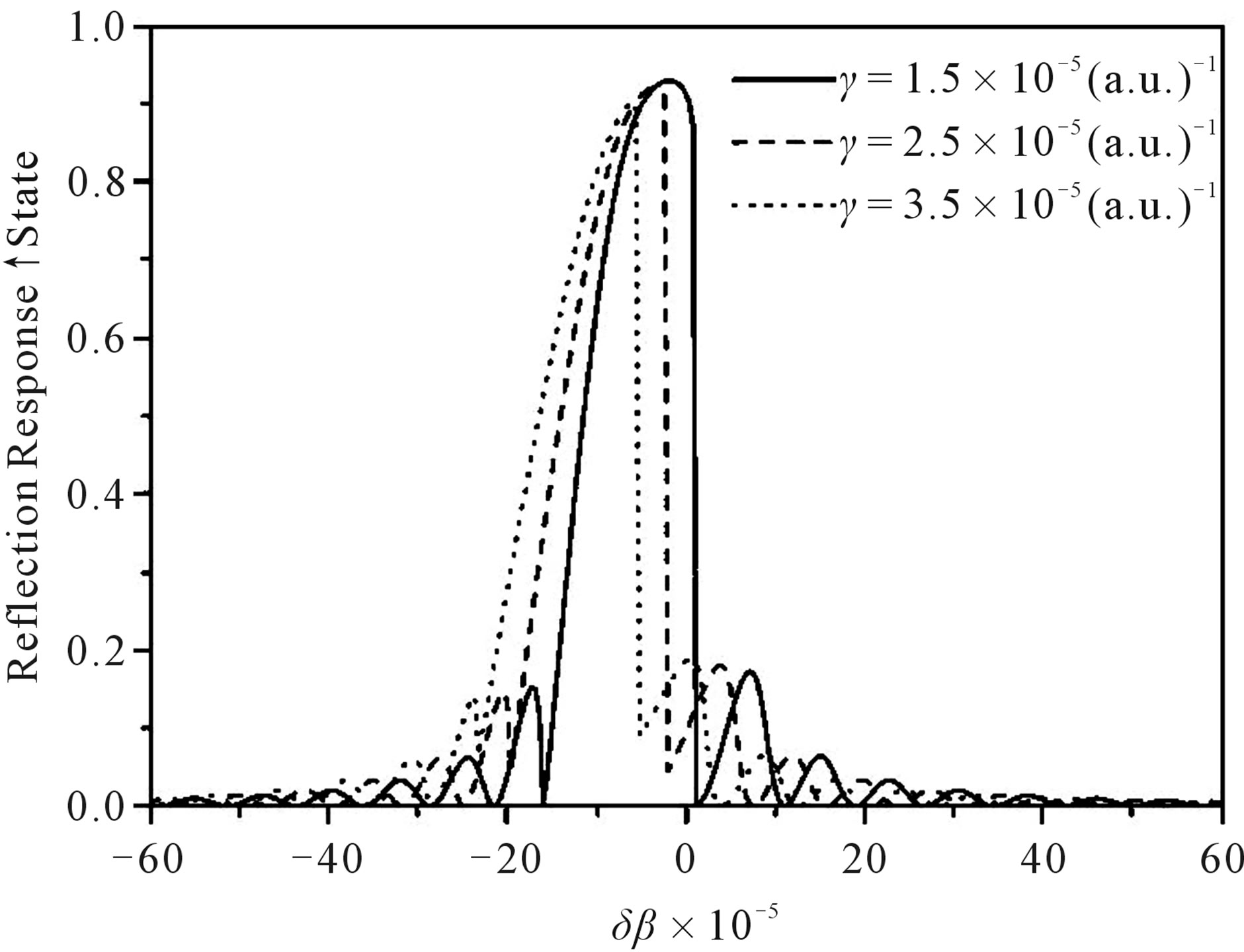
All calculations were done simulating a L = 10 mm length grating centered in 1550 nm. The coupling function  for gratings is a 5 mm full width at half maximum Gaussian function. First let’s see what occurs when a monochromatic beam propagates in nonlinear gratings. In Figure 3 one show reflection responses in both switching states for three different nonlinear parameter gratings. First thing to note is that the peak center is dislocated from the matching condition
  in the linear case. This dislocation is higher as γ increases.
Furthermore, with the increment of the nonlinear parameter the reflection characteristic peak in bistability state is reduced followed by a decrease in the grating bandwidth. This behavior is also presented in the increase of the ¯ state. Furthermore, the ratio between the and ¯ state bandwidths increases with γ.
4.1. Nonlinear Modulation Amplitude
We begin our study varying A, from a small perturbation
 (a)
(a) (b)
(b)
Figure 3. (a) Reflection responses in the state of three nonlinear gratings in switching state. k = 5 × 10⁻⁵; (b) Reflection responses in the ¯ state of three nonlinear gratings in ¯ switching state. k = 5 × 10⁻⁵.
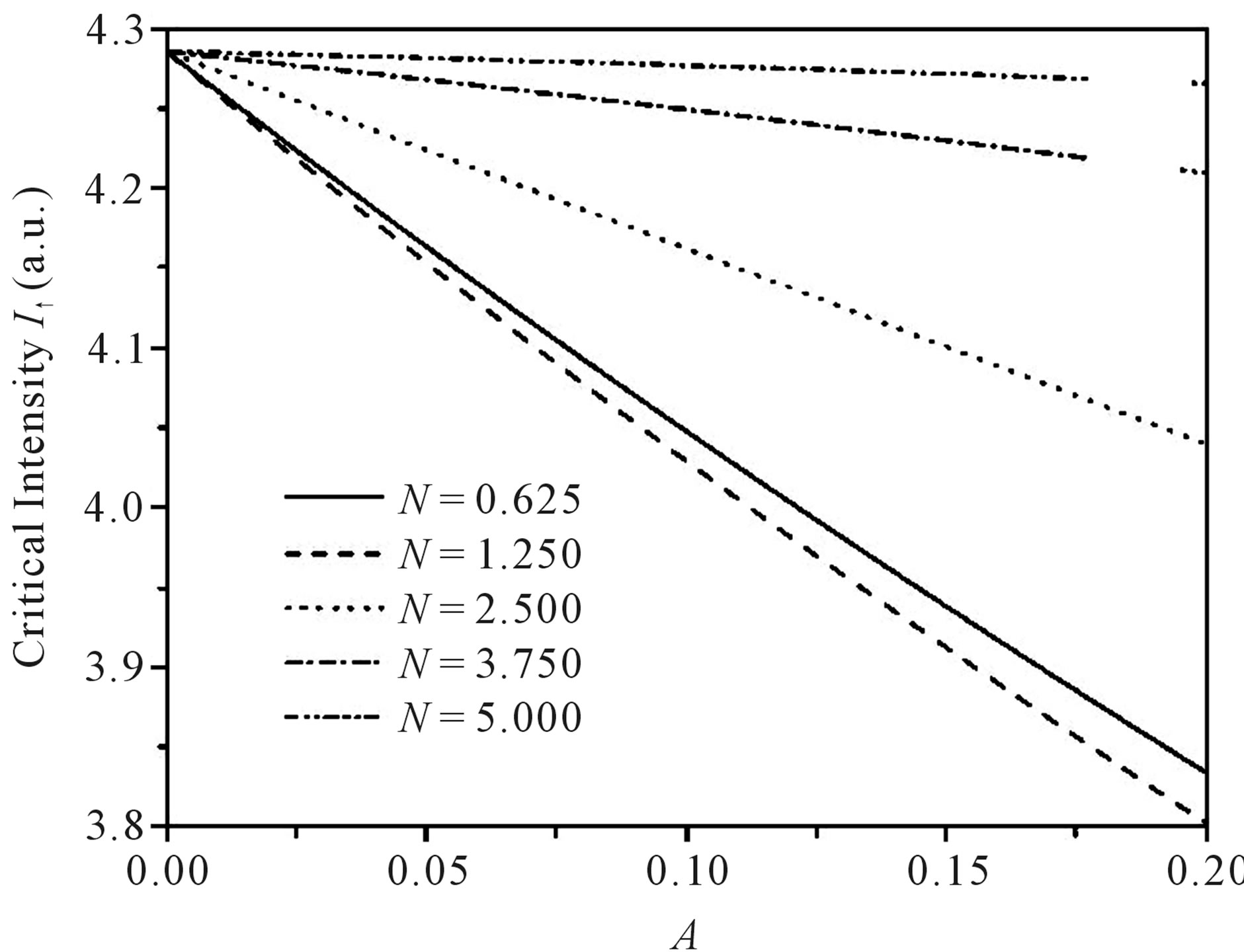
until A = 0.2. In Figure 4(a) one can see the critical intensity for state versus A for several values of N. The curves in the studied range can be taken as linear ones in good approximation. For values of N > 1 the increase of A is leading to a decrease in the inclination of the curve. The solid line curve is in the regime where there is no periodic modulation since N < 1. In Figure 4(b) is shown the dependence on A of the delta of intensities for several values of N. The curve of the N = 1.25-grating presents an oscillation along A and for small values of A presents almost the same values of δ¯ for N = 2.5-grating. With the increase of A arises an appreciable difference between N = 1.25 and N = 2.5 curves. One can also note that according to Figure 1(b) the bistability curves presents different critical values for different values of N, modifying the characteristics of switching, according to Equation (7), where the parameter N is controlling the
 (a)
(a)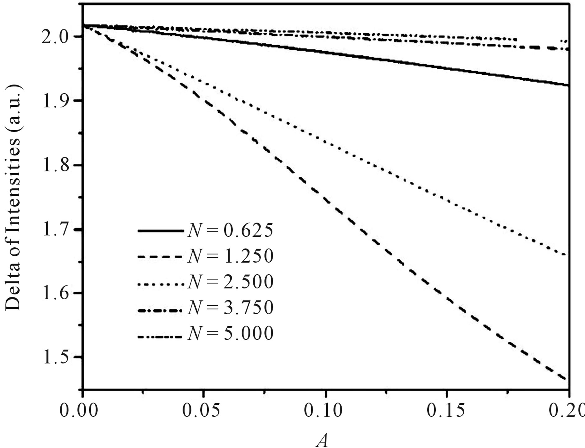 (b)
(b)
Figure 4. (a) Critical intensity I↑ versus A for different values of N. k = 5 × 10⁻⁵, γ0 = 2.5 × 10⁻⁵ (a.u.)−1, δβ = −5 × 10⁻⁵, φ = 0; (b) Delta of intensities δ↑↓ versus A for different values of N. k = 5 × 10⁻⁵, γ0 = 2.5 × 10⁻⁵ (a.u.)−1, δβ = −5 × 10⁻⁵, φ = 0.
nonlinearity parameter of the Bragg grating. The critical intensity and the delta of intensities are also a function of the A parameter. For intermediate values, a case becomes interesting, when N = 1.25 is compared with the case where N = 0.625, (note Figure 4(a)), this can be justified due to the different critical intensity values shown in the bistability curve (see Figure 1(b)). The same happens in Figure 4(b), for the cases N = 1.25 and N = 2.5 delta values decrease as A increases, compared with N = 0.625.
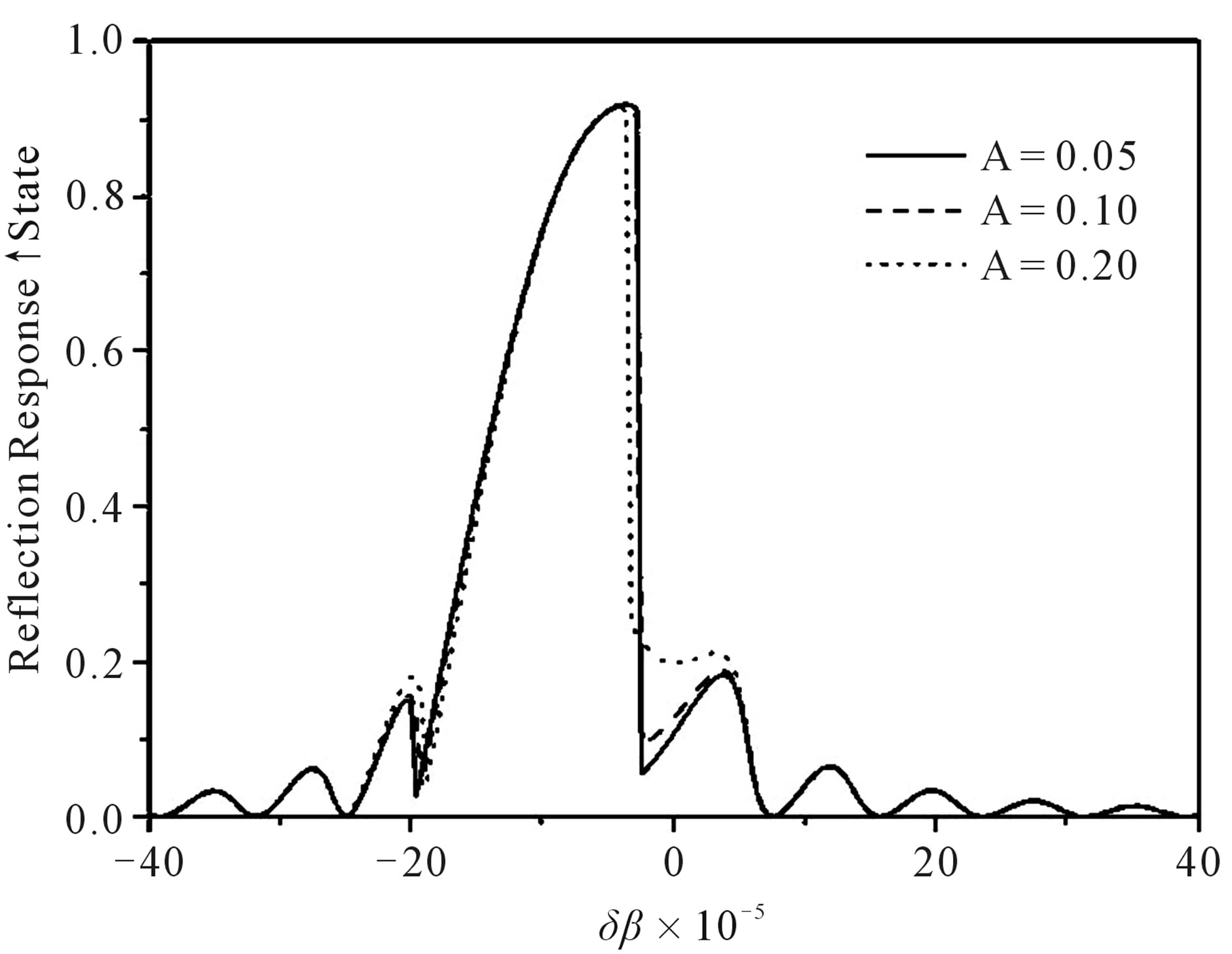
With the increase of A, an appreciable difference between N = 1.25 and N = 2.5 curves is observed. For high values of N the switching parameters present a linear dependence with a small inclination with the increment of A. In every case the increment of A increases the switching parameters: I and δ¯. In despite of this linear dependence of switching parameters on A, the reflection characteristics present appreciable difference when A is varied as seen in Figure 5.
When intensity grows, the reflectivity peak  is leading to decrease (increase) in modulated NLFBG’s on (¯) bistability state compared with regular NLFBG’s as shown in Table 1. The bandwidth of the grating decreases (increases) for modulated gratings. For reflection filter applications the uniformity of the reflectivity peak is needed to provide an unvarying filtered intensity in both bistability states. In that case the relation between |Hmax|2/|Hmax|2 must be close to one.
For pulse reshape applications the relation between the bandwidths in both states must be as high as possible. Modulation amplitude γ0A increment leads to drastic decrease of the bandwidth ratio between switching states, as seen in Figure 3. The modulation increases the grating
 (a)
(a)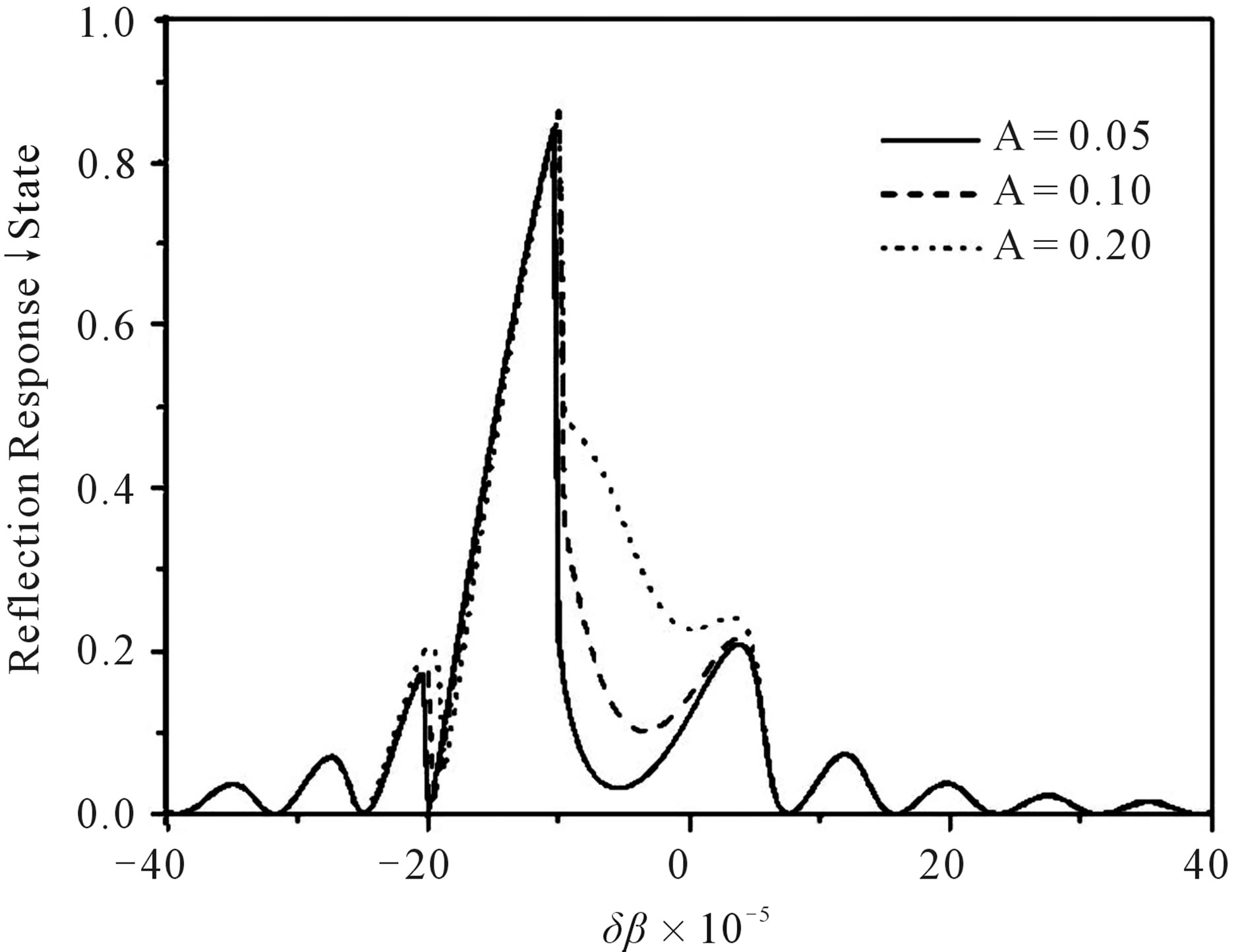 (b)
(b)
Figure 5. (a) Reflection responses for different values of A in state for an CW input intensity I = 2 a.u. k = 5 × 10⁻⁵, γ0 = 2.5× 10⁻⁵ (a.u.)−1, N = 1, φ = 0; (b) Reflection responses for different values of A in ¯ state for an CW input intensity I = 2 a.u. k = 5 × 10⁻⁵, γ0 = 2.5 × 10⁻⁵ (a.u.)−1, N = 1, φ = 0.
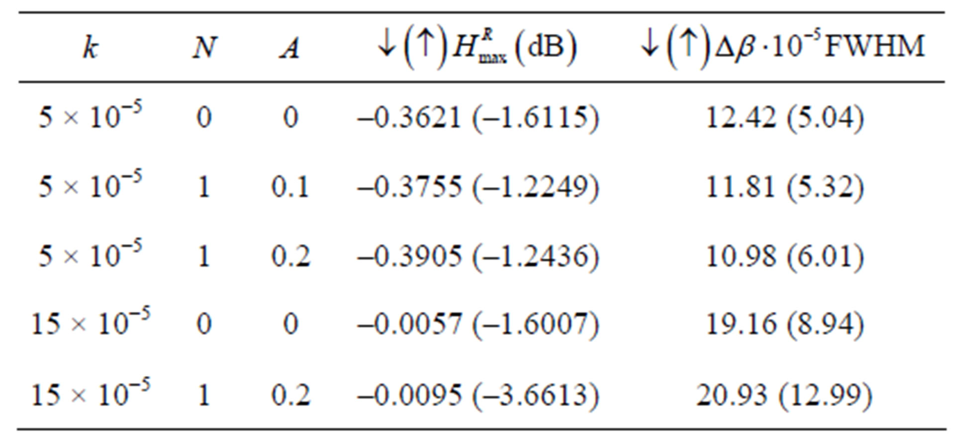
Table 1. Reflection Characteristics of a CW input signal through some nonlinear fiber Bragg gratings. (L = 1 cm, λB = 1550 nm, I0 = 2 a.u).
bandwidth in both states for strong gratings.
4.2. Nonlinear Modulation Wave Number
There are some different cases when the nonlinear modulation wave number variation is considered:
1) when N < 1;
2) when N is very large;
3) when items above are not satisfied.
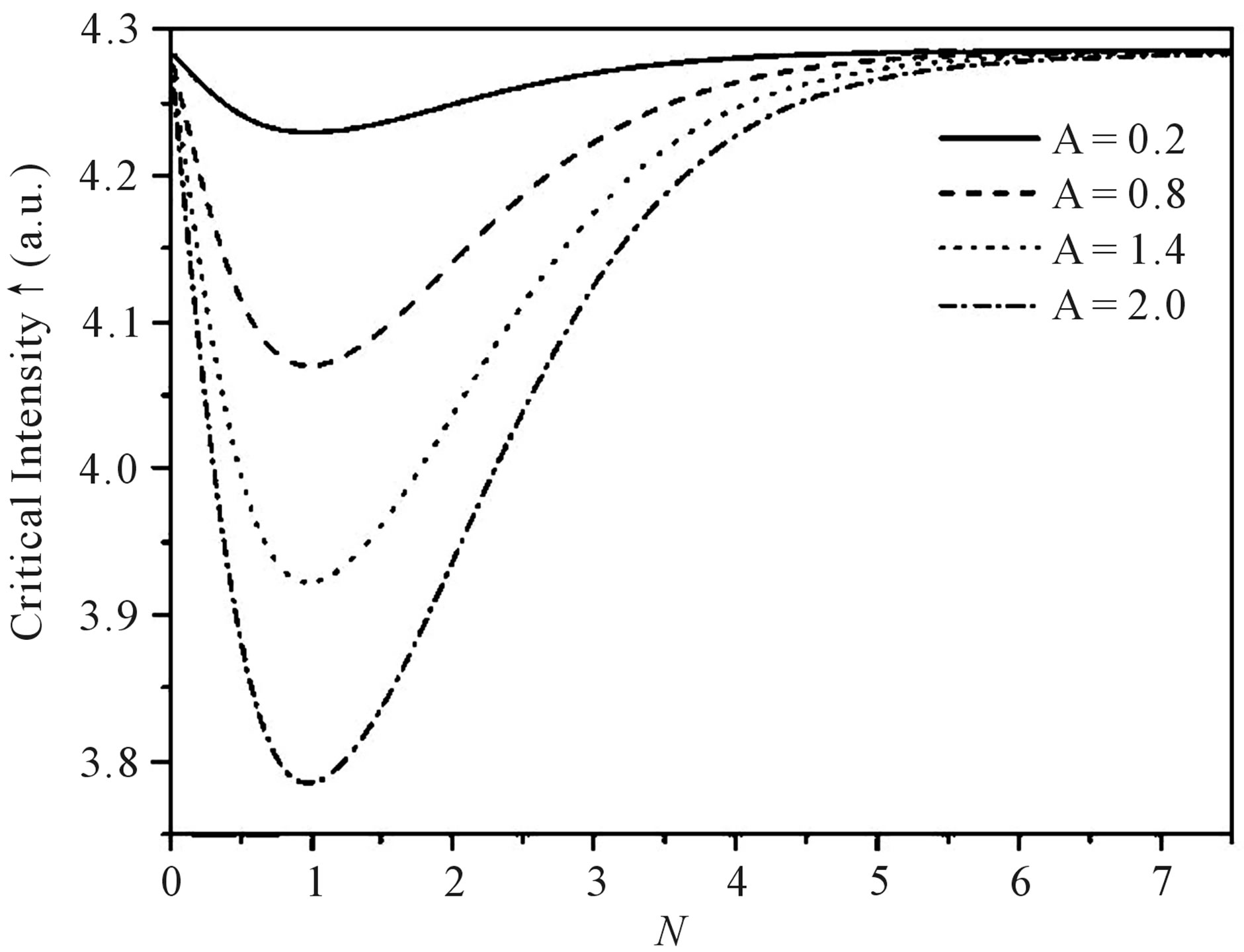
When N is too small 1), there is no periodic modulation of nonlinearity, instead there is a profile of nonlinearity. When N is very large 2), it is expected that the periodic modulation looks like as a fast fluctuation around the unmodulated value γ0, since the sin-function average is zero. Under this view, we expect precisely small dependence on switching parameters for high N. When item 3) holds, one should expect, the periodic modulation regime. There is a linear dependence on the switching parameters of the A parameter. This can be seen from Figures 6(a) and (b) where critical intensity I and delta of critical intensities respectively are plotted versus N for some values of A (gratings with φ = 0). In those cases the variation of N with different A’s presents a minimal value in N = 1. Figure 6(a) shows the critical intensity I versus N. There is a minimum in these curves in N = 1, as N increases the I value approaches the unmodulated gratings value γ0. This is an indication that condition (2) is obtained for N values around 7.
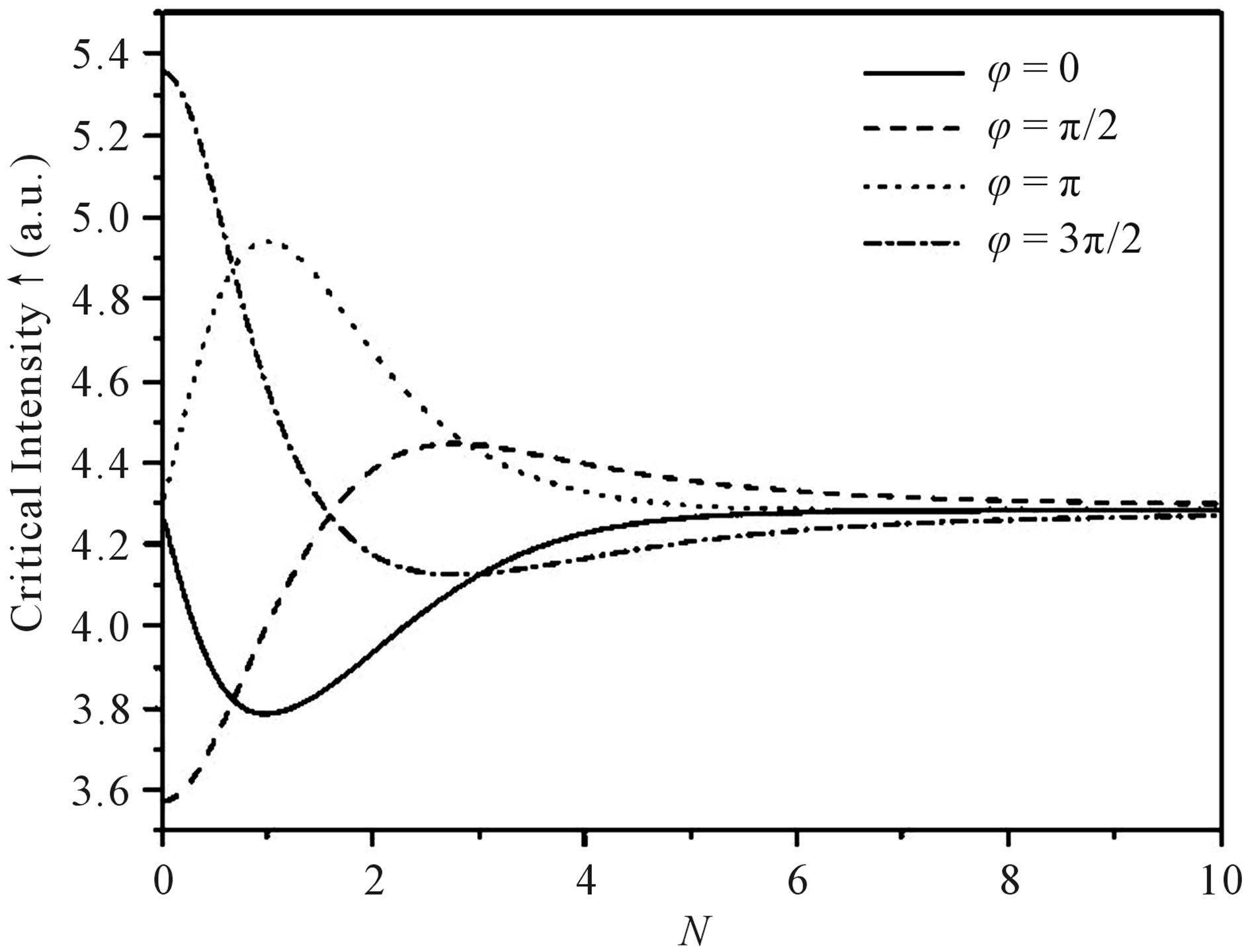
The Figures 7(a) and (b) shows the switching parameters dependence on nonlinear modulation wave number N for different φ-phased gratings. We can see from Figure 7(a) that the variation of N implies in damped like oscillation of the first critical intensity. Depending on the nonlinear modulation phase, φ, the oscillation presents first minimum or maximum in the function. For high value of N the first critical intensity value comes near the unmodulated NLFBG value. This is associated to the fact that high N-grating behaves as an unmodulated NLFBG. Note that when φ equals to π/2 or 3π/2 (for low N values), the first critical intensity differs from unmodulated nonlinear grating value. This is explained noting that for very low N the grating has a nonlinear function value
 (a)
(a)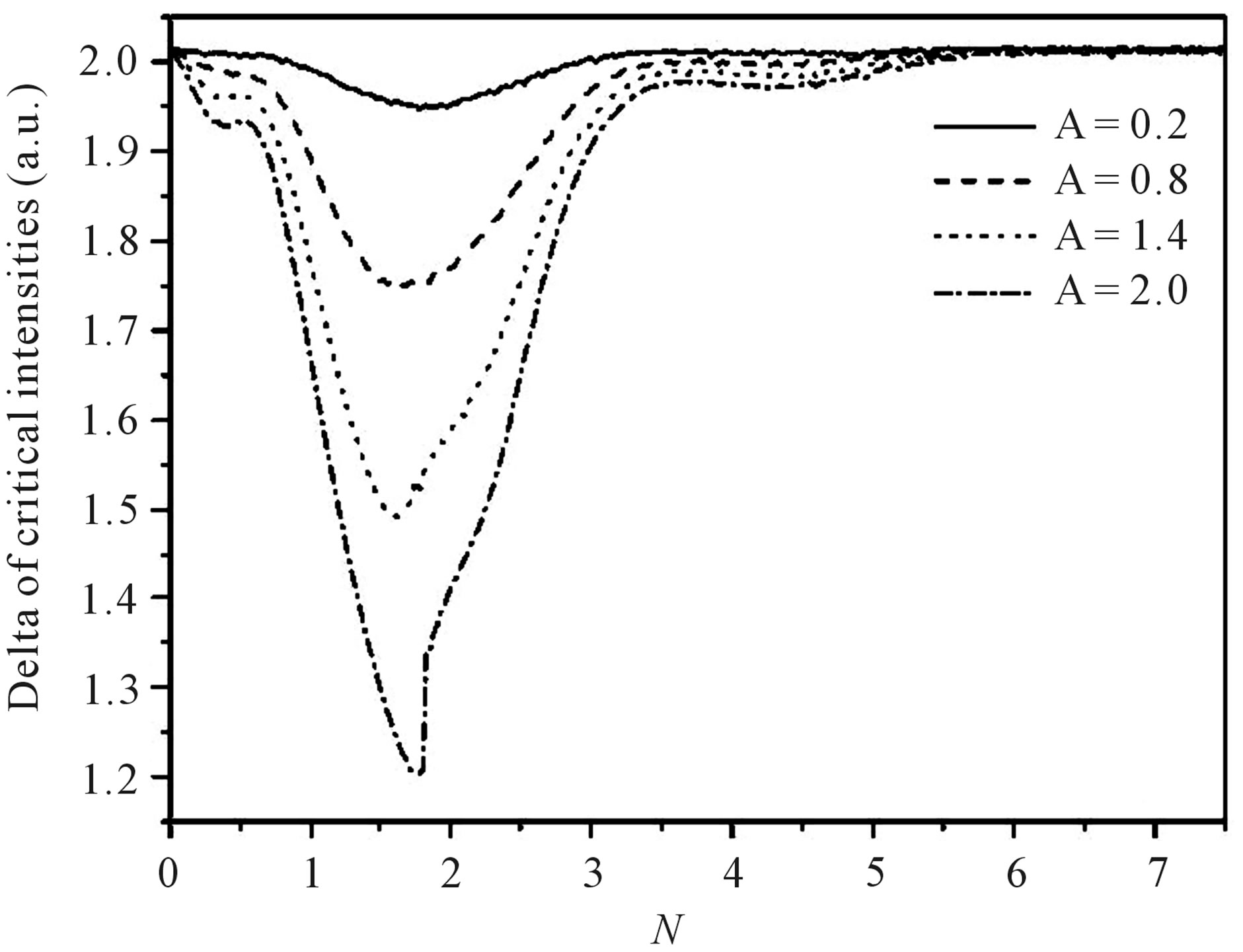 (b)
(b)
Figure 6. (a) Critical intensity I↑ versus N for different values of A. k = 5 × 10⁻⁵, γ0 = 2.5 × 10⁻⁵ (a.u.)−1, δβ = −5 × 10⁻⁵, φ = 0. 6; (b). Delta of intensities δ¯ versus N for different values of A. k = 5 × 10⁻⁵, γ0 = 2.5 × 10⁻⁵(a.u.)−1, δβ = −5 × 10⁻⁵, φ = 0.
approximated by γ0 [1 + A sin(φ)]. The Figure 7(b) shows the delta of intensities dependence on N. Because of the irregular damped oscillation of the second critical intensity with N, the behavior of δ¯ becomes irregular. It is important to have smaller I compared with the unmodulated NLFBG’s values and with bigger δ¯. This is achieved for N = 0.59, N = 2.60, N = 1.85 and N = 1.21 for φ equals to 0, π/2, π and 3π/2-gratings, respectively.
5. Conclusions
In this work, numerical studies on the switching characteristics of a nonlinear fiber Bragg grating (NLFBG) with modulation in the third order nonlinear index of refracttion along it’s length, operating in a continuous wave regime (CW) is presented. The dependence on the amplitude of modulation (A) of the switching parameters was found approximately linear and the inclination of the
 (a)
(a) (b)
(b)
Figure 7. (a) Critical intensity versus N for different values of φ. k = 5 × 10⁻⁵, γ0 = 2.5 × 10⁻⁵ (a.u.)−1, δβ = −5 × 10⁻⁵, A = 0.2. 7; (b) Delta of critical intensities _"# versus N for different values of φ. k = 5 × 10⁻⁵, γ0 = 2.5 × 10⁻⁵ (a.u.)−1, δβ = −5 × 10⁻⁵, A = 0.2.
curves decreases with the increment of N (nonlinear modulation wave number) for N > 1. The high nonlinearity modulation wave numbers N is leading to modulated NLFBG act like an unmodulated NLFBG. In that configuration the periodic modulation is not perceived by the input light. The most interesting results related to N variation are in the range 0 - 4. For N > 4 the switching properties of the grating approaches asymptotically to the properties of an unmodulated grating. If the grating is required for an efficient nonlinear switching application one can manufacture a grating with specific properties (critical intensities and δ¯) solely setting the modulation parameters (N, φ, A) at the fabrication time.
6. Acknowledgements
The authors would like to thank Conselho Nacional de Desenvolvimento Científico e Tecnológico CNPq, CAPES and FUNCAP.
REFERENCES
- W. W. Morey, G. A. Ball and G. Meltz, “Photoinduced Bragg Gratings in Optical Fibers,” Optics & Photonics News, Vol. 5, No. 2, 1994, pp. 8-14. doi:10.1364/OPN.5.2.000008
- H. Lee and G. P. Agrawall, “Nonlinear Switching of Optical Pulses in Fiber Bragg Gratings,” IEEE Journal of Selected Topics in Quantum Electronics, Vol. 39 No. 3 2003, pp. 508-515. doi:10.1109/JQE.2002.808165
- H. Zoweil and J. W. Y. Lit, “Bragg Grating with Periodic Non-Linearity as Optical Switching,” Optics Communications, Vol. 212, 2002, p. 57. doi:10.1016/S0030-4018(02)01892-8
- R. Kashyap, “Fiber Bragg Gratings,” Academic Press, San Diego, 1985, pp. 197-221.
- F. A. Hopf and G. I. Stegeman, “Applied Classical Electrodynamics,” Linear Optics, Vol. 1, 1985, pp. 148-152.
- F. A. Hopf and G. I. Stegeman, “Applied Classical Electrodynamics,” Nonlinear Optics, Vol. 2, 2007, pp. 122- 125.
- H. G. Winful, J. H. Marburger and E. Garmire, “Theory of Bistability in Nonlinear Distributed Feedback Structures,” Applied Physics Letters, Vol. 35, No. 5, 1979, pp. 379-381. doi:10.1063/1.91131
- L. R. Chen, S. L. Benjamin, P. W. E. Smith and J. E. Sipe, “Ultrashort Pulse Reflection from Fiber Gratings: A Numerical Investigation,” IEEE/OSA Journal of Lightwave Technology, Vol. 15, No. 8, 1997, pp. 1503-1512.