Journal of Electromagnetic Analysis and Applications
Vol.4 No.1(2012), Article ID:17146,8 pages DOI:10.4236/jemaa.2012.41001
Numerical Modeling of the Coupled Electromagnetic and Mechanical Phenomena of Linear Stepping Motors
![]()
Laboratoire des Technologies Avancées en Génie Electrique (LATAGE), Département d’Electrotechnique, FGEI, Université Mouloud Mammeri de Tizi-Ouzou, Tizi-Ouzou, Algeria.
Email: {zbmust, mhemed_rachek}@yahoo.fr, benamrouchen@yahoo.com
Received November 14th, 2011; revised December 13th, 2011; accepted December 24th, 2011
Keywords: Numerical Modeling; Electromagnetic-Mechanical Phenomena; Finite Element; Movement; Stepping Motors
ABSTRACT
In this paper, we propose an electromagnetic-mechanical model based on the finite element and Macro-Element (ME) technique to analyse and study the dynamic characteristics of a Tubular Linear Switched Reluctance Stepping Motor (LSRSM). After the resolution of the non-linear electromagnetic equation governing the behaviour of the different materials of the motor using the nodal-based finite element method, this equation is then coupled to the mechanical equation firstly through the magnetic force computed by Maxwell stress tensor, and secondly by the modified flux distribution due to the moving part. Because of the precision required in the mobile part displacement and the very small air gap of stepping motors, the simulation of the movement is assured by the Macro-Element (ME) technique compared to other movement techniques that present many disadvantages. The validity of the developed model is verified through the comparison of the computed displacement of the LSRSM moving part with those given experimentally [2]. The Results shows satisfactory agreement. The obtained dynamic characteristics, particularly the starting magnetic force, are obtained by considering two values of the supplying currents.
1. Introduction
Linear stepping motors can produce a higher force at very low speed and they can be used as direct drive actuators for different devices as robots, medical machine tools, and computer peripheries. The interest in this kind of electromechanical linear devices is growing due to the absence of mechanical transmissions or gear trains which leads to higher control bandwidth and dynamic performance, higher positioning accuracy, improved reliability and significant maintenance reduction. Because of these reasons, linear stepping motors have been used in a wide range of applications in recent years. Among these motors, we particularly distinguish Tubular Linear Switched Reluctance [1-5], and hybrid Stepping Motors [6-9].
In recent years, several works have been published in the field of mathematical modelling [1-3,6,7] such as the analytical and the equivalent magnetic circuit developed for analysing the behaviour of the electromagnetic and the mechanical phenomena occurring in linear stepping motors.
If for the analytical models, the major difficulty concerns the mathematical solution of the partial derivative equation which needs many assumptions that are usually not-realistic, the equivalent magnetic circuit suffers from the difficultly in its application to the moving parts [6,7]. These short comings limit the accuracy of these models while applied to linear stepping motors.
The aim of this paper is to develop an electromagneticmechanical coupled model which takes into account different phenomenon governing this kind of devices such as saturation of the ferromagnetic materials, and the accuracy of displacement. Based on the Finite Element Method (FEM) and the Macro-Element technique (ME), this model is implemented under MATLAB environment and applied to analyse and to investigate the dynamic characteristics of a linear tubular switched reluctance stepping Motor (LSRSM) principally the starting magnetic force, the displacement and the velocity.
The LSRSM is governed by the magnetic field nonlinear equation expressed in terms of Magnetic Vector Potential (MVP) in the case of two-dimensional cylindrical coordinates. This equation is solved using the Finite Element Method (FEM) combined with the NewtonRaphson algorithm for the treatment of the magnetic non-linearity due to the reluctivity—magnetic flux density dependence approximated by the classical Marrocco’s formula [10].
The mechanical model is given by the classical motion equation which is numerically solved using the fourth order Runge Kutta method to get the displacement and the velocity. This equation is coupled with the magnetic field equation through the magnetic force which is computed by Maxwell stress tensor method and the modified flux distribution due to the moving part displacement. The high accuracy required for taking into account the moving parts in the linear stepping motors has led us to adopt the Macro-Element (ME) technique [11,12] compared to the movement techniques used in [2,3,13-16] to simulate the movement in linear devices. The ME technique is based on the analytical solution of Laplace equation in the unmeshed air-gap region which separates the meshed fixed and mobile regions. The unmeshed air gap appears as a multi-nodes finite element, and therefore while the moving region displaces, only the node coordinates of the air-gap element are moved which permits to maintain unchanged the mesh topology at each displacement step. The movement technique used in [2,3] to study the same motor (LSRSM), the topology of the mesh is changed at each displacement of the moving part; in this case some distortion of the elements (triangles) appears along the displacement in the air-gap, this distortion will cause errors in computing the magnetic forces. Without any constrains on the mesh topology, the major advantages of the ME technique is the possibility to compute, with precision, the magnetic force by the Maxwell stress tensor method particularly when the air gap is very small and the displacement is variable and precise. It is the case in stepping motors.
The numerical solution of the electromagnetic-mechanical coupled model at each step displacement leads to compute the local quantities such as the magnetic vector potential, the magnetic flux density, and to predict the global quantities which are the magnetic force, the displacement and the velocity.
The results are obtained by considering two values of the supplying currents corresponding respectively to the region of almost linear characteristic and near the knee of the magnetisation curve. To check the validity of the developed model, we compare the predicted displacement of the LSRSM to those obtained experimentally and given in [2].
2. Electromagnetic-Mechanical Modeling
2.1. Electromagnetic Finite Element Formulation
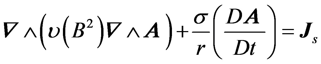
Starting from Maxwell’s equation, neglecting the displacement current, and taking into account the magnetic nonlinear material properties, the governing magnetic field equations in term of magnetic vector potential is given in the 2D cylindrical coordinates  as follows:
 (1)
(1)
 (2)
(2)
 (3)
(3)
 (4)
(4)
where  is the magnetic reluctivity of material,
  is the magnetic vector potential,
  is the flux density,
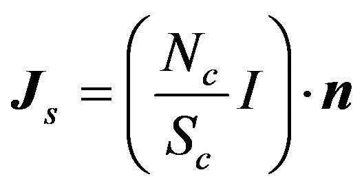
  is the exciting current density,
  and
and  are respectively the number of turns and the cross-sectional area of the coil,
  is the unit vector along the direction of the exciting current
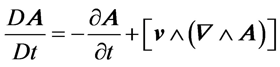
  and
and  is the body velocity.
Both the stator and the rotor are made of ferromagnetic material which are meshed and separated by an unmeshed air gap known as the Macro-Element. To complete the formulation of Equation (1), boundary conditions are necessary especially in the ME. Since the displacement is simulated by means of Macro-Element, the connection between the fixed and the moved meshes is achieved through the MVP analytical expression at each node of the ME boundary.
While eddy currents are totally neglected and the movement implicitly taken in charge by the considered ME frame, the current fed Expression (1) associated to the Macro-Element technique is written in space discretised form using the Galerkin finite element method as follows:
 (5)
(5)
where  is the modified electromagnetic potential vector,
  is the vacuum reluctivity,
  is the Macro-Element boundary,
  is the boundary surrounding the meshed regions area
 ,
,  is the area containing the conductors.
  is the weighted function.
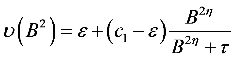
The magnetic reluctivity of the considered ferromagnetic materials is approximated by the classical Marrocco’s formula obtained from the magnetisation curve of the material. The reluctivity-magnetic flux density dependence is described by the parameters  [10]:
[10]:
 (6)
(6)
Using the first order triangular finite element, the magnetic vector potential is given by means of the approximation functions  and
and  for each finite element
  respectively of the meshed node regions and the unmeshed Macro-element boundary nodes:
 (7)
(7)
With  and
and  are the numbers of the meshed region nodes and Macro-Elements boundary nodes respectively. The contribution of the Macro-Element to the global stiffness matrix is considered by the term of the matrix
  and is given by [11,12] as:
 (8)
(8)
 (9)
(9)
 and
and  are the boundaries of the Macro-Element and
 its length.
The introduction of approximation functions of the magnetic vector potential (7) in Equation (5) for each node, leads to the following algebraic equation system:
 (10)
(10)
where  is the stiffness matrix,
  is the excitation vector due to the current source. The stiffness matrix and excitation vectors terms are expressed by the following expressions:
 (11)
(11)
 (12)
(12)
The magnetic flux density magnitude is imposed by the current, and consequently defines the materials magnetisation level. When lower currents are imposed, the magnetic reluctivity is considered constant and therefore the electromagnetic problem becomes linear.
On the other hand, when high currents are applied, high magnetic flux densities are obtained leading to saturation. The material local saturation phenomenon is represented by the use of the magnetic reluctivity-magnetic flux density (6), and then the electromagnetic problem becomes nonlinear. The treatment of the electromagnetic nonlinear problem is performed through the Newton-Raphson algorithm which leads to solve the residual algebraic equation system:
 (13)
(13)
where, the right term represents the residual vector given as follows:
 (14)
(14)
where is the Jacobian matrix and
  and
and  is the iteration number.
For linear electromagnetic equation in term of magnetic vector potential and with taking into account the Macro-Element stiffness matrix, we will obtain for the first order triangle the following matrix:
 (15)
(15)
where  is the radial component and
  is the triangle area.
The application of Newton-Raphson method for the
first equation of system (15) in the case of non-linear electromagnetic equation, leads to the following system represented in matrix notation:
 (16)
(16)
The same treatment is performed to all equations of system (15) leading to the following global matrix:
 (17)
(17)
2.2. Mechanical Equation
The mechanical model of the moving parts is obtained by the classical Newton equation given by the following differential equation:
 (18)
(18)
where  is the mass of the moving part,
  the displacement,
  the magnetic force,
  is the force developed by the load,
  the friction force,
  the viscosity coefficient, and t the time.
The displacement and the velocity are obtained after solving Equation (18) by using the fourth order Runge Kutta scheme.
The force is efficiently computed as the integral of Maxwell stress tensor along a surface enclosing the moving parts located in the air with vacuum magnetic reluctivity. While considering a circular surface of radius  around the body, the force in the z-direction is given by:
 (19)
(19)
Derived from the magnetic vector potential, the axial and radial magnetic flux density components respectively  and
and  are computed. After the discretisation of the integral form (19) for each finite element, the force is given as follows:
 (20)
(20)
 is the distance between the barycenters of two successive finite elements bound to the air gap,
  is number of nodes of successive finite elements along the air gap.
3. Description of the Studied Stepping Motor
The considered stepping motor is a tubular linear switched reluctance stepping motor. The geometrical characteristics of the LSRSM, with the consideration of two modules are presented in Figure 1 [1-3]. The dimensions of the structure are detailed in Table 1.
4. Results and Discussion
Only one fourth of the motor structure is analyzed due to symmetry. The homogeneous Dirichlet condition of the magnetic vector potential is imposed at the boundary  and at the symmetry axis
 .
.
Figure 2 shows the finite element mesh topology used in [2,3] for the study of the LSRSM structure. To compute the magnetic force with Maxwell stress tensor method, it is important to have a regular air-gap discretisation and also a strong density meshing as shown in Figure 2. At each displacement step of the moving part, the mesh of the domain must be changed. To avoid the distortion of the elements (triangles) in the air-gap, the control of the regularity and the density of the mesh is assured by the calculation of the fragmentation rate [2] at each step of the displacement. It represents the ratio between the two orthogonal edges of the mesh right-angled triangles (Figure 3):
 (21)
(21)
In our model, the mesh conditions cited in [2,3] are not needed, the Macro-Element technique is proposed to simulate the movement. In this case, we need only one and the same mesh topology at each displacement step of the moving part without control of the distortion of the elements in the air gap. Figure 4 shows the finite element mesh topology associated to the Macro-Element used to solve the electromagnetic-mechanical problem of the developed model. The ME takes into account the variable displacement steps which are obtained through the mechanical equation in a precise manner without any mesh readjustment, and allows accurate calculations of the magnetic force by the Maxwell stress tensor method particularly when the air gap is very small. It is the case
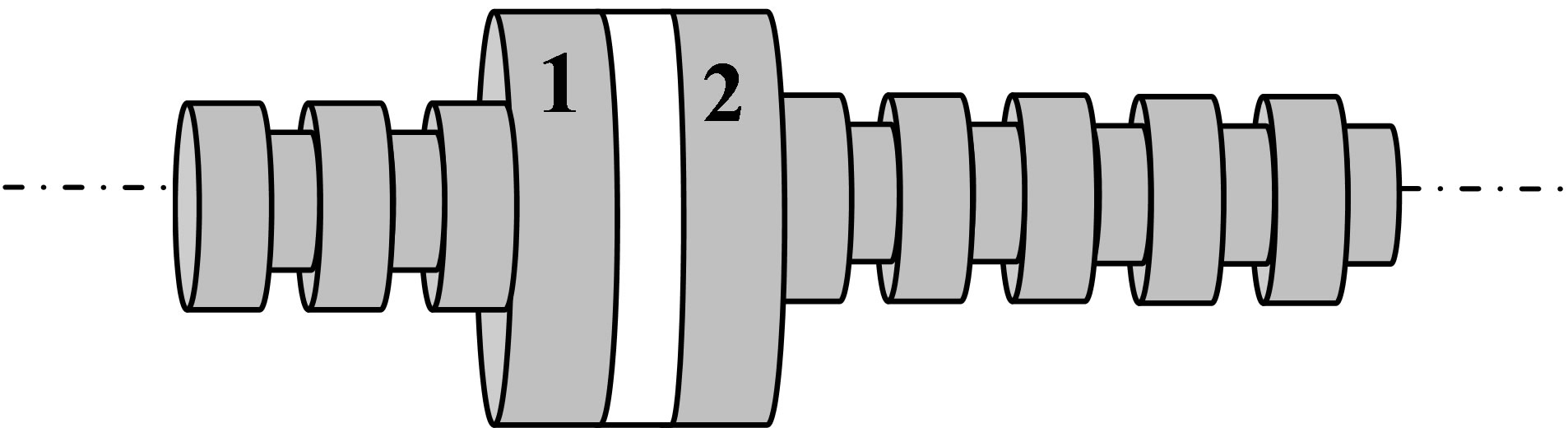

Figure 1. LSRSM structure.
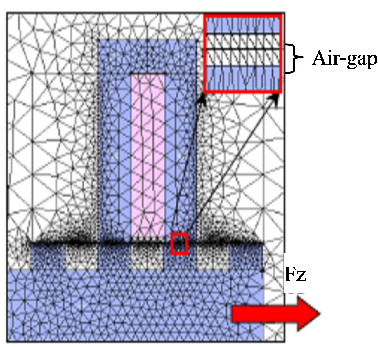
Figure 2. Finite element mesh [2].

Figure 3. Air-gap mesh element [2].

Figure 4. Finite element mesh associated to the MacroElement.
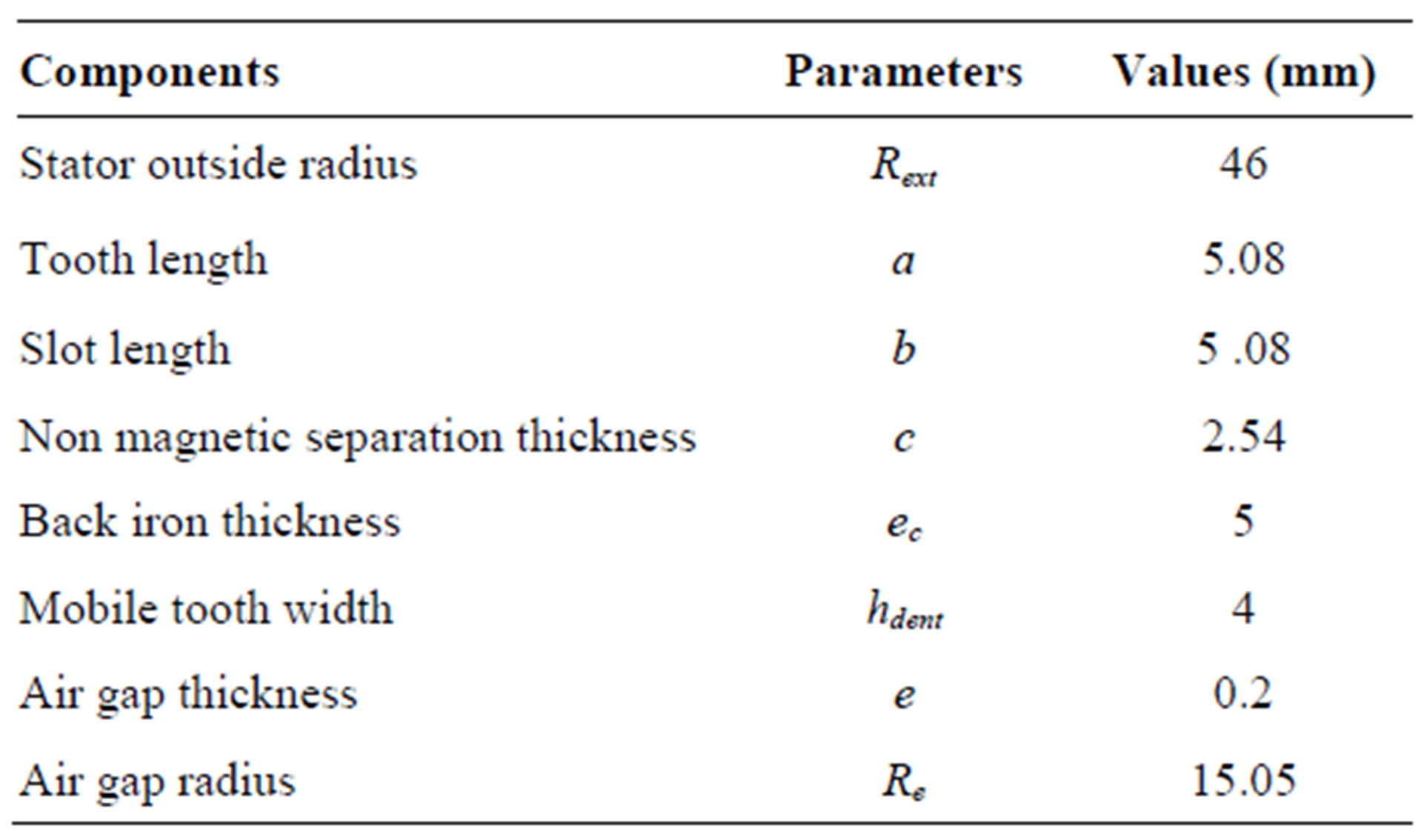
Table 1. Geometrical characteristics of the LSRSM structure.
in the studied LSRSM, where the air gap is of 0.2 mm.
 and
and  indicated in Figure 4 represent the distance of the boundaries of the Macro-Element and
  is its length, such as given in Equation (9).
The determination of the dynamic characteristics of the LSRSM is conducted for two excitation current values NCI = 300 At, and NCI = 450 At corresponding to the almost linear and near the knee of the magnetisation curve of the considered material.
The mechanical characteristics of the structure are m = 5 Kg, ξ = 0.65 Ns/cm, f0 = 0.1 N. The parameters of Equation (6) are respectively, ε = 1.1 × 10⁻⁴, c1 = 1, η = 5.23 and t = 7.02 × 10⁴.
To check the validity of the developed model, the computed displacements of the moving part of the LSRSM given in Figure 5, are compared to the experimental values given in [2], as shown in Figure 6. As it can be seen, good agreement is achieved. This characteristic presents some oscillations around its equilibrium position which is equal to 2.54 mm corresponding to the elementary step displacement of the motor.
The computed displacement versus time result shown in Figure 6 is obtained by using the commercial code OPERA-2D combined to the experimental data. It should be noted that the OPERA-2D solve only static electromagnetic problems [2].
Figures 7 and 8 show respectively the flux lines and the distribution of the magnetic flux density in the LSRSM structure.
Figure 9 shows the magnetic vector potential distribution along the Macro-Element at the initial and the final positions of the moving part in the LSRSM. The magnetic vector potential waveform for the initial and the final positions are similar. The slight difference shown in Figure 9 is due to the displacement of the moving part. This explains the accuracy achieved by the Macro-Element technique.
Figure 10 illustrates the distribution of the magnetic flux density in the air-gap where the maximum is of 0.8 T. The picks are due to the form of the LSRSM teeth.

Figure 5. Displacement versus time (LSRSM) obtained by the developed model for NcI = 300 At.
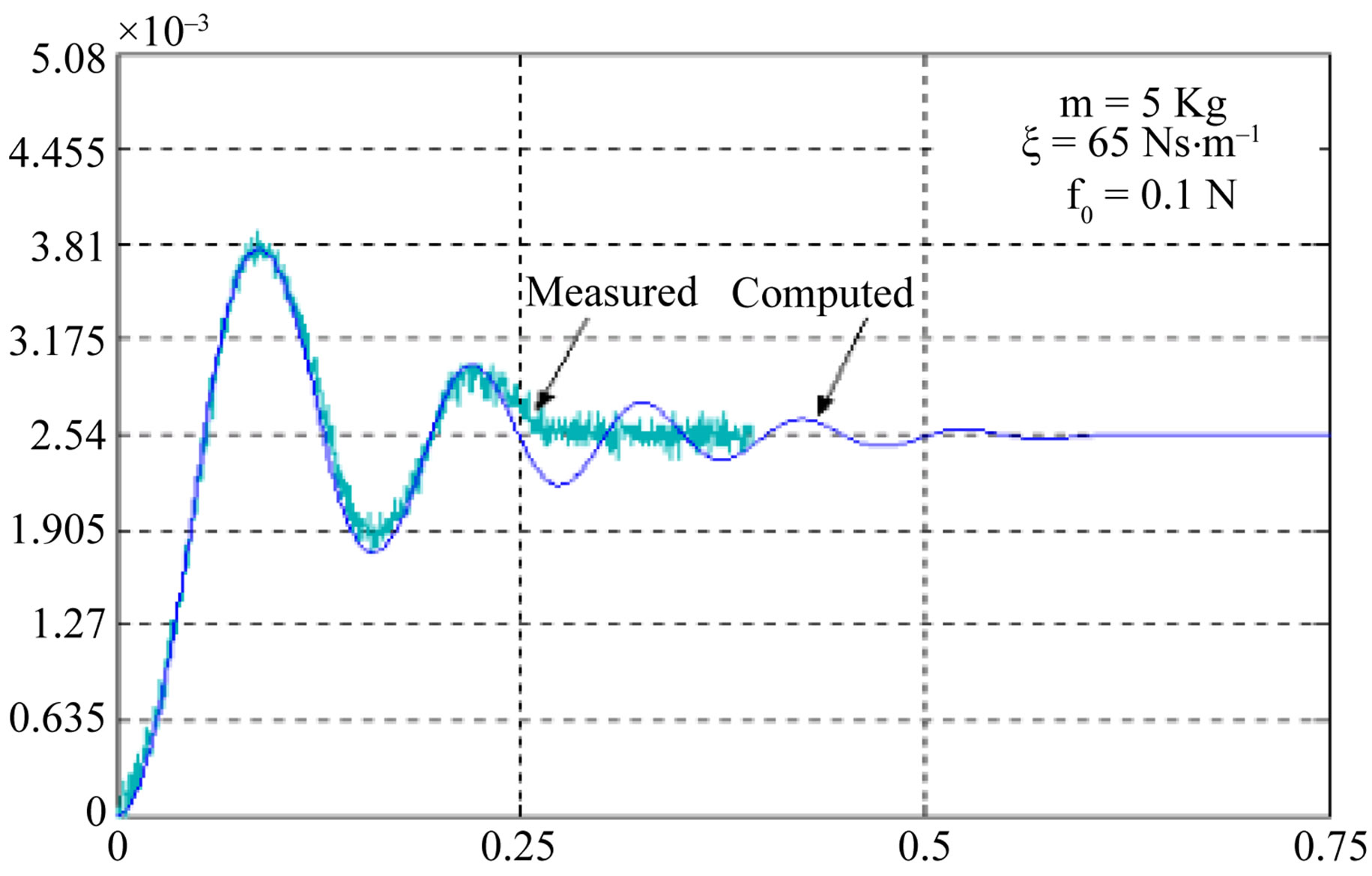
Figure 6. Displacement versus time obtained by [2] for NcI = 300 At.

Figure 7. Flux lines in the LSRSM for NcI = 300 At.

Figure 8. Magnetic flux density in the LSRSM for NcI = 300 At.

Figure 9. Magnetic potential vector along the Macro-Element for NcI = 300 At.
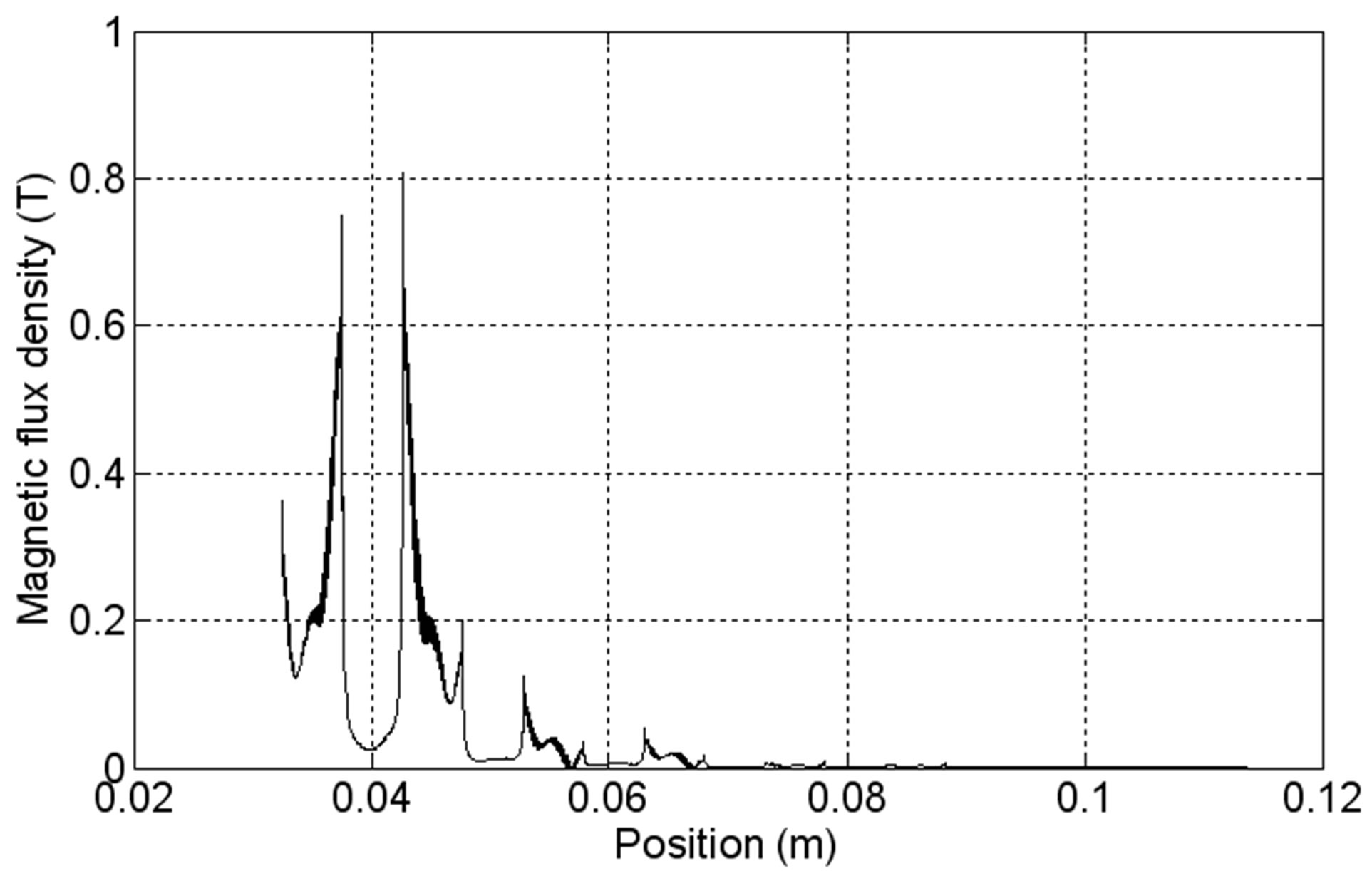
Figure 10. Magnetic flux density in the air gap of LSRSM for NcI = 300 At.
5. Dynamic Characteristics of the Stepping Motor
The dynamic characteristics of a LSRSM for different supply currents are presented in Figures 11-13. These figures show respectively the displacement versus time, the velocity versus time and the starting magnetic force versus time when the LSRSM structure is supplied by two currents values, NCI = 300 At and NCI = 450 At.
In Figure 11, the moving part of the motor starts from the rest position to reach a maximum of 3.75 mm for NCI = 300 At and 4.25 mm for NCI = 450 At. The steady state is achieved after 0.6 s where the motor reaches the final position at 2.54 mm corresponding to elementary displacement step. Figure 12 shows the velocity versus time for the two supply currents showing that effectively the velocity is stabilized at 0.6 s around the zero value corresponding to reaching its final position for the step which represents the rest position.
The same phenomena are observed with starting magnetic force show in Figure 13.
Figures 11-13 show that the transient state over shoots and natural frequencies are increasing with the increase
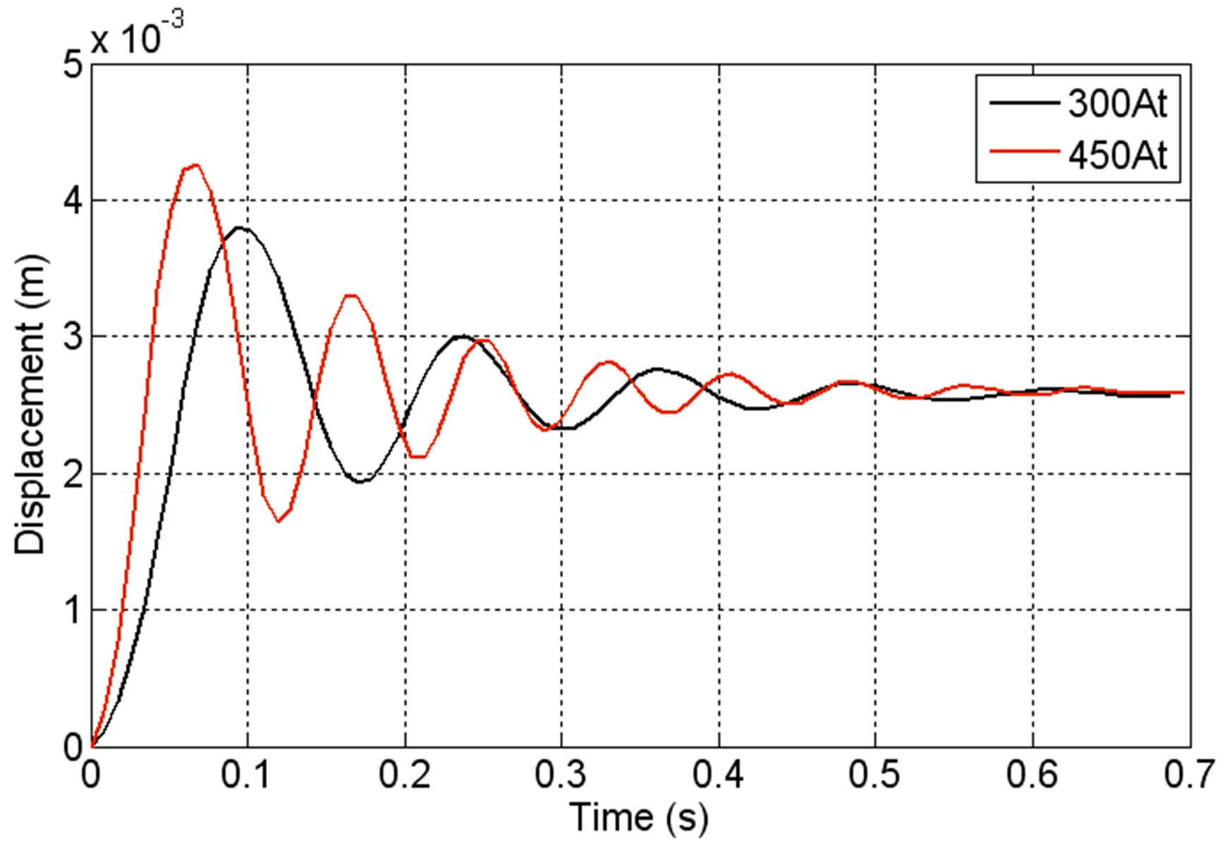
Figure 11. Displacement versus time.
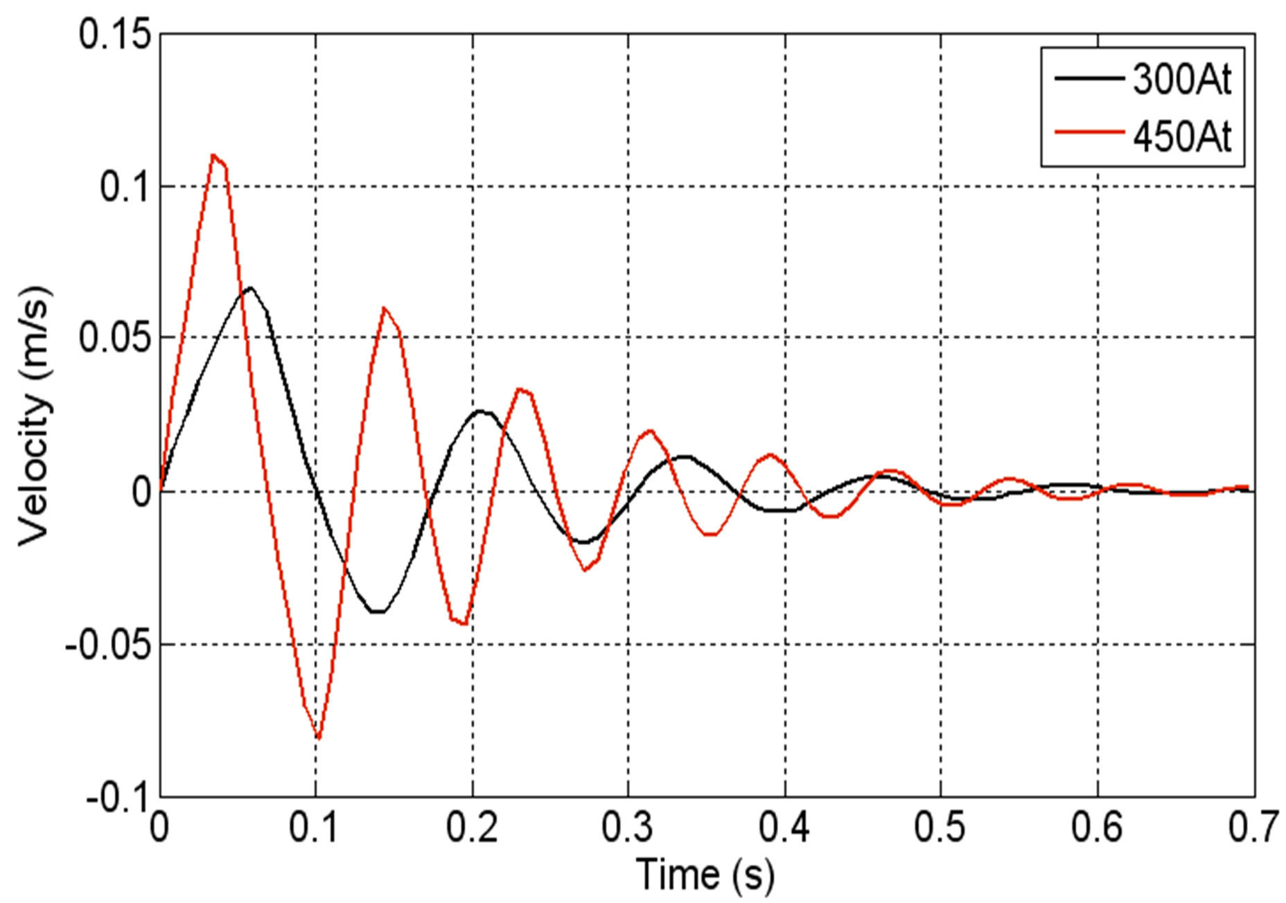
Figure 12. Velocity versus time.
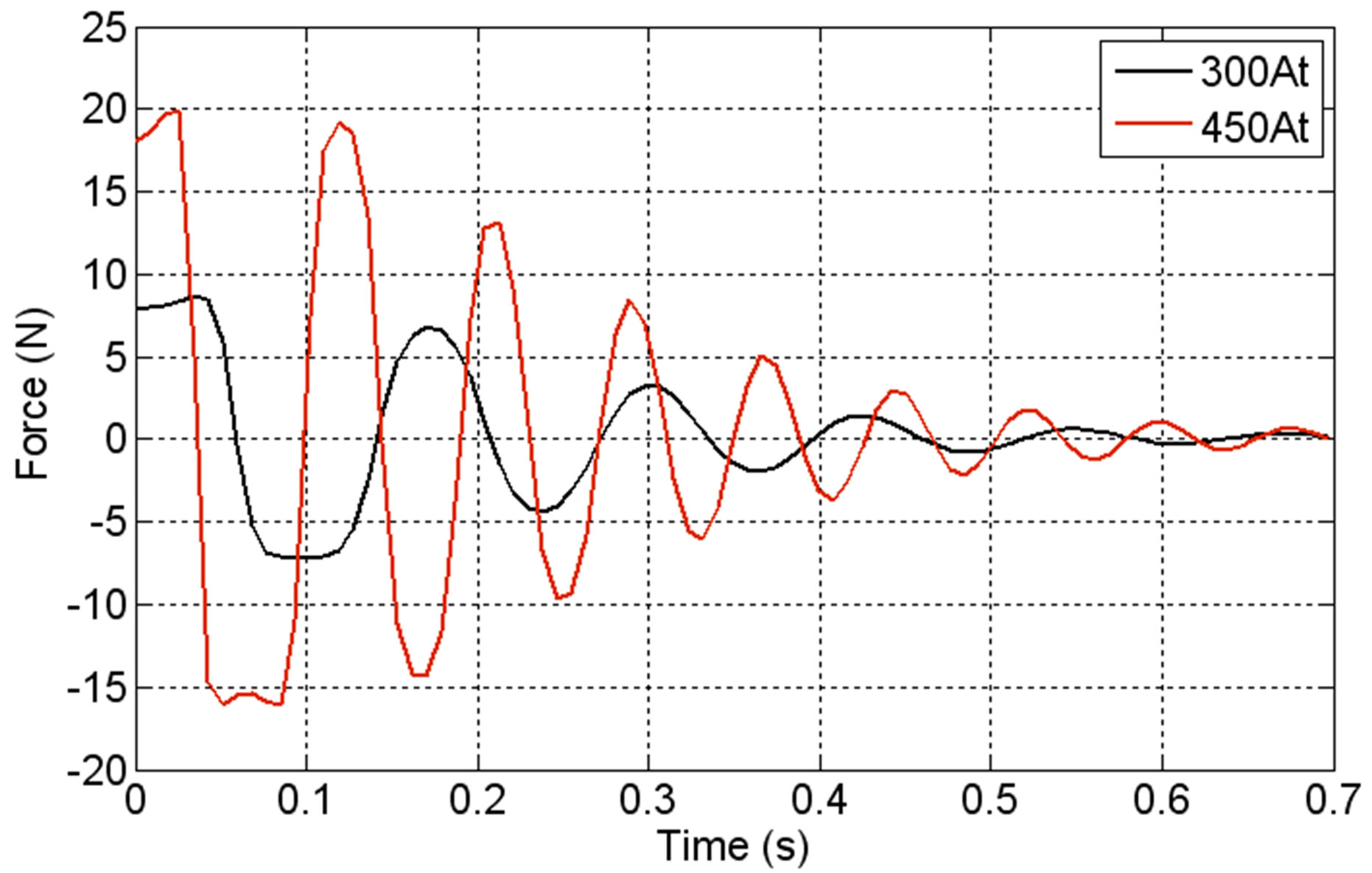
Figure 13. Starting magnetic force versus time.
of the supply current. This may be explained by the fact that the model is developed to handle LSRSM open loop operations. However, conclusions concerning the developed model could be drawn as the rest position after an elementary displacement step corresponding to the time where the force and velocity are null.
6. Conclusion
The electromagnetic-mechanical coupled model described in this paper is applied to study and analyse the dynamic characteristics of linear stepping motors. The proposed model takes into account several phenomena governing this kind of devices such as saturation effects of the materials, the mechanical phenomenon and the displacement of the moving part. Based on the finite element and the Macro-Element technique, the model is implemented under MATLAB. Due to the very small air gap and the accuracy of displacement steps, the Macro-Element is indicated to simulate the movement without constraints compared to others movement simulation techniques. The validity of the developed model was assessed by comparing the ccomputed displacement to those given experimentally in [2]. The results showed good agreements. The dynamic characteristics such as the starting magnetic force and the velocity are obtained for two excitation current values corresponding to a region of almost linear magnetisation curve and near its knee.
REFERENCES
- W. Missaoui, L. EL Amraoui, F. Gillon, M. Benrejeb and P. Brochet, “Performance Comparison of Three and FourPhase Linear Tubular Stepping Motor,” Proceeding of the ICEM06, Paper No. 467, Greece, 2006.
- L. EL Amraoui, “Conception Electromécanique d’une Gamme d’Actionneurs Linéaires Tubulaires à Réluctance Variable,” PH.D. Thesis, University of Sciences and Technology of Lille, Lille, 2002.
- L. EL Amraoui, F. Gillon, S. Vivier, P. Brochet and M. Benrejeb, “Optimal Design Approach for Tubular Linear Machine,” 2002 IEEE International Conference on Systems, Man and Cybernetics, Hammamet, 6-9 October 2002.
- L. EL Amraoui, F. Gillon, S. Vivier, P. Brochet and M. Benrejeb, “Robust Electromagnetic Optimization of Linear Tubular Actuators,” IEEE Transactions on Magnetics, Vol. 40, No. 2, 2004, pp. 1192-1195. doi:10.1109/TMAG.2004.825304
- L. EL Amraoui Ouni, F. Gillon, P. Brochet and M. Benrejeb, “Use of Inverse Models Built for Accurate Micro Stepping of Linear Switched Reluctance Step Actuator,” IMACS Multiconference on Computational Engineering in Systems Applications (CESA), Beijing, 4-6 October 2006, pp. 424-430.
- A. K. Daud and R. Hanitsch, “Linear Stepping Motor (LSM) with Reduced Force Ripple,” Symposium on Power Electronics, Industrial Drives, Power Quality, Traction Systems, Capri, 16-18 June 2004, pp. 870-874.
- D. Casadei, C. Rossi, G. Serra and A. Tani, “Optimal Design of a Tubular Hybrid Stepping Motor under Volumetric Constraints,” Symposium on Power Electronics, Industrial Drives, Power Quality, Traction Systems, Capri, 16-18 June 2004, pp. 857-853.
- J.-K. Seok, T.-S. Hwang and D.-H. Kim, “Initial Position Estimation for Closed-Loop Linear Hybrid Stepping Motor Drives Using DC Excitation,” IEEE Transactions on Magnetics, Vol. 42, No. 8, 2006, pp. 2071-2076. doi:10.1109/TMAG.2006.875838
- T.-S. Hwang and J.-K. Seok, “Observer-Based Ripple Force Compensation for Linear Hybrid Stepping Motor Drives,” IEEE Transactions on Industrial Electronics, Vol. 54, No. 5, 2007, pp. 2417-2424. doi:10.1109/TIE.2007.900344
- A. Marroco, “Analyse Numérique des Problèmes d’Électrotechniques,” Annale des Sciences Mathematiques du Quèbec, Vol. 1, No. 2, 1977, pp. 217-296.
- H. Mohellebi, M. E. Latrèche and M. Féliachi, “Coupled Axisymmetric Analytical and Finite Element Analysis of Induction Devices Having Moving Part,” IEEE Transactions on Magnetics, Vol. 34, No. 5, 1998, pp. 3308-3310. doi:10.1109/20.717777
- F. Azzouz, B. Bendjima and M. Féliachi, “Application of Macro-Element and Finite Element Coupling for the Behaviors Analysis of Magnetoforming System,” IEEE Transactions on Magnetics, Vol. 35, No. 3, 1999, pp. 1845- 1848. doi:10.1109/20.767392
- M. Zaouia, H. Mohellebi and M. Abdellah, “ElectricMagnetic-Mechanical Coupled Model for Analysing Dynamic Characteristics with Feeding Effects of Linear Induction Launcher,” IASME Transactions, Vol. 1, No. 2, 2004, pp. 235-240.
- M. Rachek, M. Zaouia, H. Denoun and C. Birouche, “Finite Element Computational Model for Defect Simulation and Detection by Eddy Currents Non Destructive Testing,” CD-ROM Proceedings of the 9th WSEAS International Conference on Circuit and Systems, Athens, 11-13 July 2005, Paper No. 497-304.
- M. Rachek, M. Zaouia, H. Denoun and C. Birouche, “Two-Dimensional Finite Element Numerical Modelling of Eddy Current Non Destructive Testing for Defect Simulation and Detection and Sensor Movement Simulating by Geometrical Band technique,” WSEAS Transactions on Circuits and Systems, Vol. 4, No. 6, 2005, pp. 574- 582.
- M. Rachek, M. Feliachi and M. Zaouia, “Three Dimensional Finite Element Modelling for Sensor Movement Simulation by Geometrical Band and Nodal Interpolation Techniques in Eddy Current Non Destructive Testing,” WSEAS Transactions on Circuits and Systems, Vol. 4, No. 6, 2005, pp. 535-542.