Journal of Electromagnetic Analysis and Applications
Vol. 3 No. 3 (2011) , Article ID: 4389 , 4 pages DOI:10.4236/jemaa.2011.33013
Improvement of Antenna Radiation Efficiency by the Suppression of Surface Waves
![]()
Faculty of Electrical Engineering, Iran University of Science and Technology, Tehran, Iran.
Email: H_oraizi@iust.ac.ir, b.rezaei.iust@gmail.com
Received October 3rd, 2010; revised December 9th, 2010; accepted December 25th, 2010.
Keywords: CPW-Fed Ring Antenna, Surface Waves, Radiation Efficiency
ABSTRACT
The characteristics of coplanar waveguide (CPW) fed ring antennas (such as gain, efficiency and polarization purity) are degraded by the dielectric losses and excitation of surface waves on the substrates. To counteract such effects, we propose to remove some portions of the substrate in the vicinity of the metallic patches, which effectively eliminates the conditions for the generation of surface waves. The proposed technique is applied to a CPW-fed ring antenna and a prototype model is fabricated. The measurement data and the computer simulation results agree well and indicate the efficacy of the technique for the improvement of antenna gain and efficiency.
1. Introduction
It is desirable to improve the antenna radiation efficiency by using suitable methods to decrease the substrate dielectric losses and limit the spurious surface waves. Although the dissipation losses of available substrates are usually low, the excitation of surface waves degrades the printed antenna performance such as polarization purity and radiation efficiency [1-3]. The surface waves are always present, because the cut-off frequency of their dominant mode is zero. Surface waves move towards the antenna edges, where they radiate into space. Consequently, it is advisable to devise some techniques to suppress the surface waves and prevent them from deteriorating the antenna efficiency and generating cross-polarized fields which spoil the antenna characteristics and polarization purity.
In this paper, we propose to remove the substrate in the neighborhood of the antenna, which counteracts the conditions for the excitation of surface waves. The proposed technique is applied to a printed CPW-fed ring antenna. A prototype model of the proposed antenna is fabricated and its Characteristics are measured and compared with computer simulation results.
2. Analysis of the Printed Ring Antennas
We study the printed CPW-fed ring antenna as shown in Figure 1 as a first step. The circumference of the ring should be equal to the wavelength at the operating frequency [4-6]. The feeding system of the antenna is by a coplanar waveguide line. Figure 1 shows the geometrical dimensions of the ring antenna and its feeding system. The substrate selected is RT5880 with dielectric constant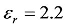 , thickness
 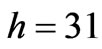 mils and loss tangent of 0.0009. The proposed antenna, which is of a resonance type, is designed as follows. Its effective radius, as the arithmetic mean of the two radii of ring, is set equal to a wavelength.


Figure 1. The CPW-fed ring antenna. Dimensions are in millimeters.
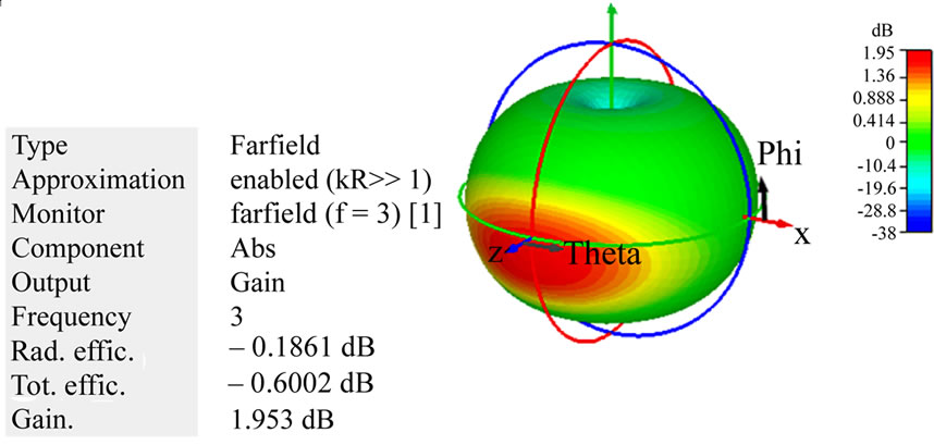
This leads to a formation of two equiphase currents on the ring, which generates the radiation perpendicular to the plane of antenna. The width of the feed line is calculated to produce a characteristic impedance of 50 ohm [7]. The width of the ring is set equal to the width of the feed line. The transition between the feed line and ring is considered as a transmission line which affects the antenna input impedance. It is optimized to minimize the return loss. The CST simulation software is used for the analysis and design of the ring antenna. Its time domain solver is based on the finite integration technique, which is used for our computer simulator. The radiation patterns of the antenna and its return loss frequency response are shown in Figure 2 and Figure 3, respectively. The return loss bandwidth at the center frequency 3.01 GHz is about 38%. The antenna gain is 1.95 dBi at 3 GHz. The related bandwidth is defined as the frequency interval where the
 (a)
(a) (b)
(b)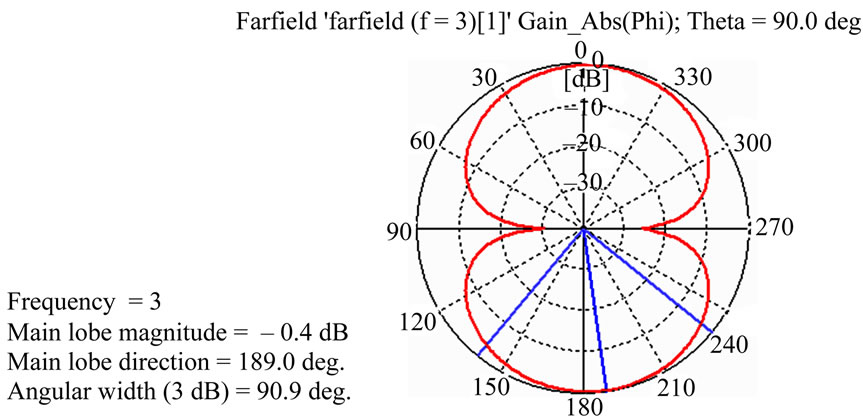 (c)
(c)
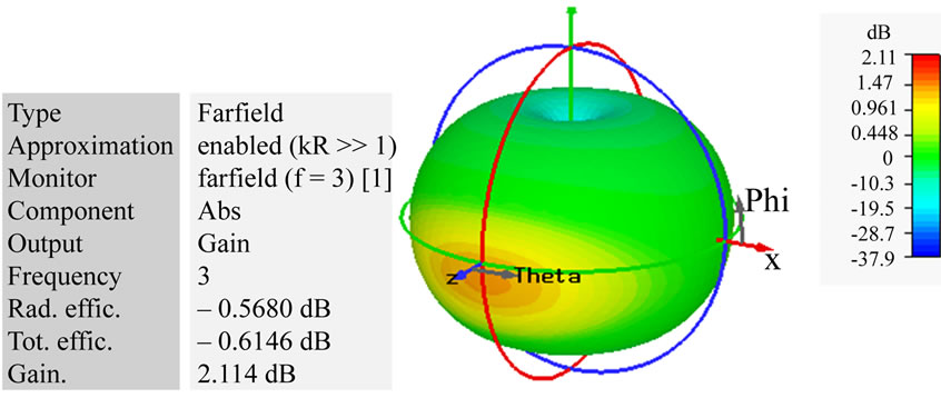
Figure 2. The CPW-fed ring antenna radiation patterns. (a) Three dimensional; (b) E-plane; (c) H-plane.
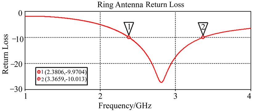
Figure 3. The CPW-fed ring antenna return loss.
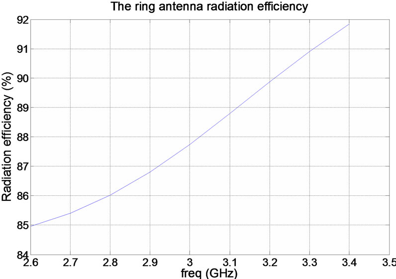
Figure 4. The radiation efficiency of CPW-fed ring antenna.
return loss is less than –10 dB. The radiation efficiency of the CPW-fed ring antenna as obtained by the computer simulation is shown in Figure 4. Observe that its radiation efficiency in the specified bandwidth varies between 85%-91%.
3. Reduction of Surface Waves
Since the cut off frequency of dominant mode of surface waves is zero, they are always present in microstrip antennas and produce spurious radiations in undesired directions, such as towards the edges of substrates as shown Figure 5.
Therefore, the radiation efficiency of the antenna gets
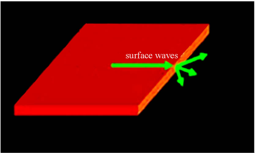
Figure 5. The propagation, radiation and diffraction of waves on the substrate.
deteriorated and its polarization purity is degraded.
Accordingly, it is proposed to cut out portions of the substrate, which are not under the metallic patches, in order to eliminate the conditions of propagation of surface waves and take them into the evanescent modes, which are drastically attenuated.
Consequently, the antenna radiation is directed mainly towards the antenna broad side direction. Note that this method is not suitable for the microstrip antennas, which operate on the basic of surface wave couplings like quasi-yagi antennas [8].
Furthermore, the removal of some portions of the substrate, changes its effective permittivity and also its operating frequency. Of course, this frequency variation is negligible. Our proposed method is applied to the CPW-fed ring antenna as shown in Figure 6, where its geometrical dimensions are also depicted. Now, some portions of the substrate are removed in such a way that they are not under the antenna layout, they do not weaken the mechanical strength and regiditaly of the antenna structure and they do not adversely affect the antenna performance. To keep the antenna performance intact, the difference between the radius of the removed disc from the substrate (rs) and the inner radius of the metallic ring (r) must be at least equal to the ring width (W2). The radiation patterns and return loss frequency response of the antenna are demonstrated in Figure 7 and Figure 8, respectively.
Note that the proposed structure of cutting out portions of substrates has little effect on the return loss, operating frequency and radiation pattern of antenna.
Furthermore, the radiation efficiency of this antenna is drawn in Figure 9, which may be compared with that of the original ring antenna. Observe that the efficiency of the proposed antenna is better than that of the original antenna by about 5%. Furthermore, the use of very low loss substrate is to distinguish between the effect of reduction of surface waves and dielectric losses.
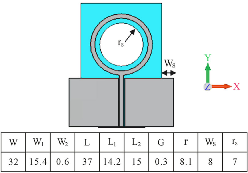
Figure 6. The modified CPW-fed ring antenna. Dimensions are in millimeters.
 (a)
(a)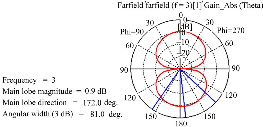 (b)
(b)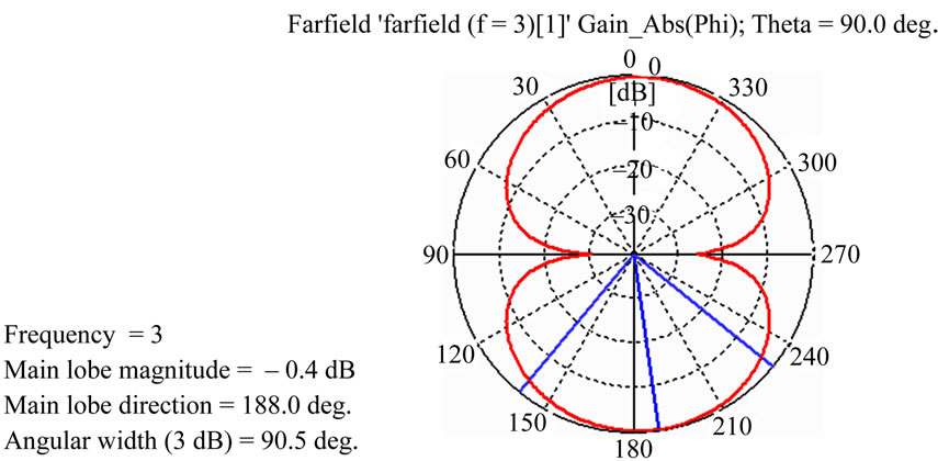 (c)
(c)
Figure 7. The modified CPW-fed ring antenna radiation patterns. (a) Three dimensional; (b) E-plane; (c) H-plane.

Figure 8. The modified CPW-fed ring antenna return loss.
4. Experimental Results and Comparison
In this section, the computer simulation results and measurement data of two fabricated prototype antennas described in Sections 2 and 3 are shown. The photographs of the ring antenna and modified ring antenna are shown in
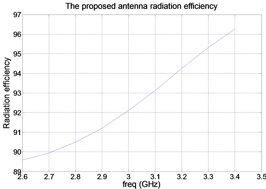
Figure 9. Radiation efficiency of the modified CPW-fed ring antenna.
The return losses versus frequency of the two antennas are also shown in Figure 10 and Figure 11. Also, the measured radiation patterns are shown in Figure 12 and Figure 13.
Observe that the computer simulation results and measurement data for the return loss of the ring antenna agree quite well (see Figure 11). The same is true for the modified ring antenna (see Figure 12). Their operating frequency intervals also coincide. The radiation patterns of the two antennas are quite similar. However, the patterns near the feed points (in Figure 13 and Figure 14) at the angle of 180˚, the measured and simulation patterns are somewhat different, which may be caused by the feed connector and cables.
Furthermore, there are some ripples in the pattern, which may be due to the antenna wide beam width (which is almost omnidirectional) and the small anechoic chamber (for such frequencies) which may generate spurious radiations, which are captured be the antenna due to it wide beam width.
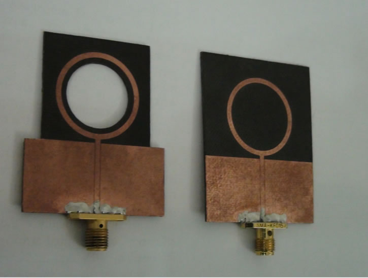
Figure 10. Photographs of the ring antenna and modified ring antenna.
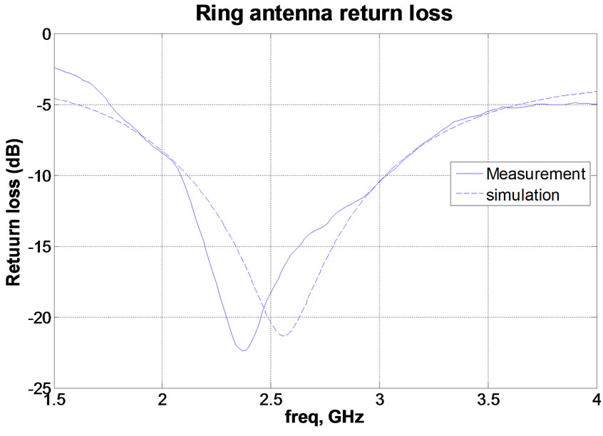
Figure 11. Simulated and measured the return loss of the ring antenna.
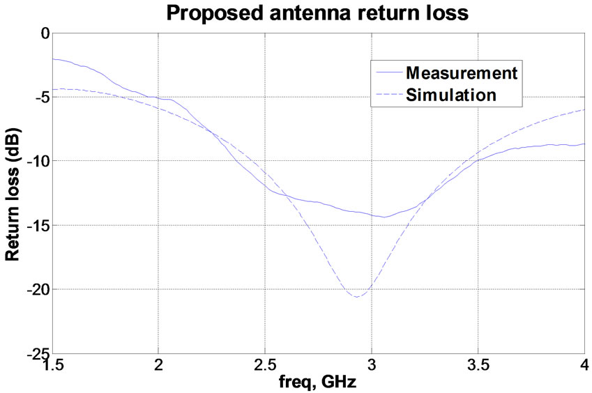
Figure 12. Simulated and measured the return loss of the modified CPW-fed ring antenna.
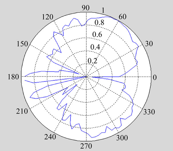
Figure 13. Printed ring antenna normalized radiation patterns (E-plane).
In order to show the efficiency of the proposed antenna structure for the improvement of antenna efficiency, the gain of two antennas may be compared. Although their gains are small, and their measurements have some errors, they may yet be compared as shown in Figure 14. Observe that the gain of proposed antenna is increased.
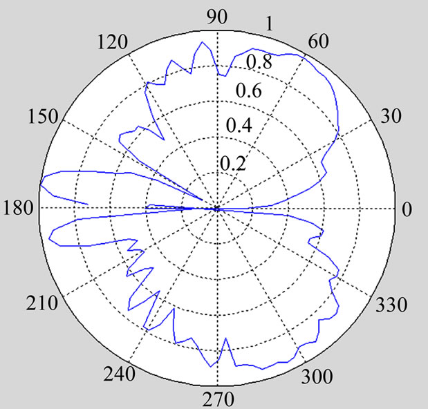
Figure 14. Modified printed ring antenna normalized radiation patterns (E-plane).
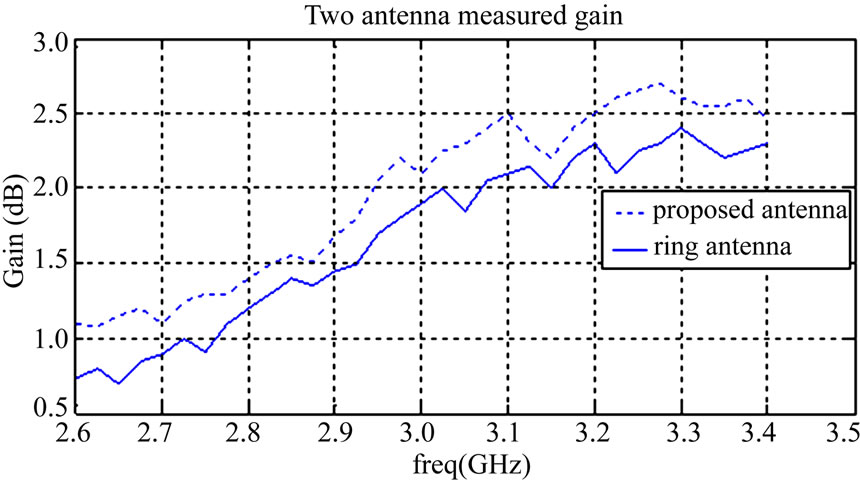
Figure 15. Ring and modified CPW-fed antenna gain versus frequency.
This feature is important in high power array antenna, where any losses can be translated to major power consumption. In arrays, the proposed method can be used to significantly increase total efficiency by decreasing mutual couplings via surface waves. The measured antenna gain versus frequency is shown in Figure 15, which demonstrates gain enhancement.
5. Conclusions
The surface waves are always excited and present on the printed antennas which propagate towards their boundaries. Consequently, they lead to the deterioration of their desired radiation properties, such as gain, efficiency and polarization purity. In order to counteract such adverse effects, we propose to remove some portions of the substrate in the neighborhood of the metallic patches. The efficacy of this technique is demonstrated by computer simulation, fabrication and measurement on a CPW-fed ring antenna. This technique may be readily applied to other types of printed antennas.
Furthermore, the proposed technique of removing dielectric substrates on the antenna structure may also be used in antenna arrays. This will cause the improvement of radiation efficiency and also the elimination of surface waves and as a result the reduction of mutual couplings among the antenna elements.
REFERENCES
- K. Fujimoto, A. Henderson, K. Hirasawa and J. R. James, “Small Antennas,” John Wiley and Sons, Research Studies Press, New York, 1987.
- K. Fujimoto and J. R. James, “Mobile Antenna Systems Handbook,” Artech House, Norwood, 1994.
- J. James and P. Hall, “Handbook of Microstrip Antennas,” Peter Peregrinus Ltd., London, 1989.
- J. Liang, C. C. Chiau, X. Chen and C. G. Parini, “Printed Circular Disc Monopole Antenna for Ultra Wideband Applications,” Electronics Letters, Vol. 40, No. 20, September 2004, pp. 1246-1248.
- W. Wang, S. S. Zhong and S.-B. Chen, “A Novel Wideband Coplanar-Fed Monopole Antenna,” Microwave and Optical Technology Letters, Vol. 43, No. 1, October 2004, pp. 50-52. doi:10.1002/mop.20372
- S.-Y. Suh, W. Shutzman, W. Davis, A. Waltho and J. Schiffer, “A Novel CPW-Fed Disc Antenna,” IEEE Antennas and Propagation Society Symposium, Monterey, Vol. 3, 20-25 June 2004, pp. 2919-2922.
- D. M. Pozar, “Microwave Engineering,” John Wiley, Hoboken, 2007.
- Y. Qian, W. R. Deal, N. Kaneda and T. Itoh, “A Uniplanar Quasi-Yagi Antenna with Wide Bandwidth and Low Mutual Coupling Characteristics,” IEEE AP-S International Symposium, Orlando, July 1999, pp. 924-927.