Journal of Electromagnetic Analysis and Applications
Vol. 2 No. 3 (2010) , Article ID: 1537 , 7 pages DOI:10.4236/jemaa.2010.23018
A Microwave-Based Invisible “Watermarking” Emulated by an Embedded Set of Electromagnetic Material in a Plastic Card
![]()
Department of Computer and Electrical Engineering and Computer Science, Florida Atlantic University, Boca Raton, USA.
Email: neelakan@fau.edu
Received November 25th, 2009; revised December 18th, 2009; accepted December 22nd, 2009.
Keywords: Microwave-Based Watermarking, Plastic Cards, Electromagnetic Materials
ABSTRACT
This article describes a passive, economical strategy towards enhancing the security feature of conventional plastic cards by embedding a set of electromagnetic (EM) material that emulates an invisible “watermarking”. This is an overlay strategy to prevailing security measures and consists of incorporating (invisibly embedding, say by ink-jet printing or otherwise) a set of foil/film-like grids of electromagnetic (EM) material (such as high-μ material or high-conductivity metal) within the cross-section of the card. The test-card when exposed to a suitable excitation of microwave (ISM band) excitation, the embedment of EM material in the card is rendered to yield distinct path-loss to the traversing EM energy. That is, by making each element of embedment a grid-frame made of vertical or set of horizontal strips, (relative to the plane of polarization of EM excitation), each grid-frame will offer high (logic 1) or low (logic 0) transmissions when the card is swiped across the EM field. By sensing appropriately, this differentiable EM attenuation across the card would depict an output signal annunciating the presence of a binary-logic encoding in the embedded “watermarking”. The proposed effort augments the existing security features of a plastic card design and robustly reduces the chances of malpractices, such as plastic card counterfeiting and misuse. The concept-design as proposed is positively verified through experimental test cards and also justified with theoretical considerations.
1. Introduction
As well known, the plastic card is mostly used as a secured entity by individuals as personal identity (ID) cards/driver’s license as well as in business transactions. But, this security-featured card often becomes susceptible for counterfeiting and unauthorized copying, scanning and photo-imaging. Therefore, provisioning extra security features as an overlay effort in such cards is imminent and complements the dynamic needs of broad customer base.
Ideally a security feature incorporated in a plastic card should enable immediate onsite verification and prevent unauthorized authentication, duplication or forgeries. Existing designs towards security embedment in plastic cards include card personalization by thermal-imaging, holographic imprints, bar-coding, embossing, magneticstripe encoding and provisioning smart-card (chip-card) capabilities. The existing standard (ISO 7810) ensures the integrity and security of the card, with the performance to an acceptable level.
Yet another, security enhancement is proposed here (as an overlay technique to the prevailing security features) that offers a value-added two levels of authenticity to the customers. It is based on a simple, cost-effective technology using microwave principles. It consists of incorporating (invisibly embedding/burying) a set of electromagnetic (EM) material [1] (such as high-μ or good-conductivity material) in foil/film-like (or ink-jet printed [2] form of) grid-frames. This embedment enables two-levels of security as follows:
When the test card is exposed to a suitable highfrequency electromagnetic (EM) excitation, the very presence of EM material offers a preset (threshold) of attenuation and hence the detected microwave strategy declares the presence of the embedded material confirming the first-level of authentication. Further, the embedded EM material (structured as an array of grid-frames) is rendered to yield a distinct attenuation (power loss) to the EM energy traversing each frame when the card is swept. The distinct attenuation refers to realizing two-levels (of high or low); and, it is accomplished with the grid design/structure having horizontal or vertical strips relative to the linear polarization of the EM excitation. The array of such vertical or horizontal grids would cause high or low attenuations to the EM wave. Sensing differential (high/low) level-changing corresponds to emulating a “watermarking” of a binary encoding of a logical (0, 1) signature. Thus, 1) by threshold-based, yes/no detection of embedded EM material and 2) by decoding the logical signature improvised by the array of grid structures of the EM material embedment, a two-prong enhancement on card identification/authenticity is realized.
Relevant concept-description, analysis, EM (microwave) excitation/sensor details, construction of a test-unit and testing are described below. Further, results are furnished towards the proof-of-the-concept. Suggested EM excitation conforms to the use of ISM 2450 MHz frequency [3]; and, the associated electromagnetics plus system considerations can be rendered not to interfere with the existing infrastructure on magnetic-core, chip-card and/or bar-code reading efforts. The proposed strategy of card authentication can be included as a part of existing/traditional card-swiping unit.
2. Embedding Information in Secured Plastic Cards: State-of-the-Art
The plastic card is a portable, wallet-size entity with embedded information and has been ushered into the society in various day-to-day applications where on-site card data retrieval is facilitated and security is implied. The generic versions of plastic cards in vogue can be listed as follows: 1) Magnetic stripe cards (ISO 7810 and ISO 7811) where data is stored in the magnetic stripe by modifying the magnetism of tiny iron-based magnetic particles placed/smeared as a band (on the magnetic stripe); 2) smart cards (ISO 7816) (also known as a chip card, or an integrated circuit card) is a critically secured card intended for financial, information technology (computer and/or communication access), government, healthcare, ID on Internet applications etc.; 3) bar-coded cards bearing bar coded information are used for simple ID as in library cards; and 4) proximity cards containing an embedded antenna transmits encoded information as a radio frequency (RF) signal (at 125 kHz or 13.56 MHz) towards identification (RFID). Picking up the encoded RF signal proximally identifies the card.
2.1 Concept of “Digital Watermarking”
Another level of security can be added to the plastic cards with “watermark” design (visible or invisible) [4]. Such watermarking decreases the illegal reproduction of the card and prevents fraud. The watermarking on plastic cards is a customized effort. It involves posting exclusively ID pictures and details printed on plastic cards. Such cards need specific digital decoding by the reader to authenticate the card. In essence, watermarking provides tamper-proofing. One popular watermarking method in use today is known as digital watermarking. The technique of digital watermarking takes its name from “watermarking” of paper or currency improvised as a security measure. Such a watermark feature is a slight imprint on paper that is nearly imperceptible unless viewed carefully, under proper conditions of optical visibility.
Digital watermarking processes involve the insertion and extraction of watermarks. In watermark insertion, the original object and a secret key are combined to produce a “stego object”, which consists of the original object with a watermark embedded in it. Later, to show authenticity or ownership of the stego object, the secret key and the stego object are combined in the process of watermark extraction, which recovers and/or verifies the presence of the watermark.
Some common types of watermarks are: 1) Visible watermarks, which depict an extension of the concept of logos. Here logos are inlaid into the image transparently; 2) invisible watermark is hidden in the content and can be detected by an authorized agency only; 3) public watermark allows reading or retrieval by anyone using a specialized algorithm; 4) fragile watermark is a tamper-proof watermarks destroyed upon data manipulation; 5) private watermark (or secure watermark) can be read only with a secret key; 6) a perceptual watermark exploits the aspects of human sensory system so as to provide invisible yet robust watermark; and 7) the so-called bit-stream watermarking is realized with compressed data (such as video).
2.2 Can a Plastic Card be Rendered with “Watermarking”?
Indicated in [4], a method of supporting traditional way of watermarking on photographic images laid on plastic cards. Presently, a microwave/EM-material based technique of “watermarking” is suggested. It is indicated as an enhanced security feature to plastic cards and is conceived by improvising an invisible watermark that can be detected (and its content analyzed) only by a special card-reading mechanism involving a microwave approach. When a card is forged, inasmuch as the implemented watermarking is absent, the card will not be authenticated by the reader as a first-level of security. Further, by proper design of the embedment set of EM material (in terms of number, size variations, and orientation of embedded elements relative to EM polarization), a digital (binary) sequence can be improvised into the “watermarking”; and, an EM sensor-cum-reading mechanism will decode this data for authentication/verification as a second-level of security. This concept of placing an EM-based watermarking in plastic cards is novel and new. To the best of the authors’ knowledge, no relevant study has been done.
3. EM Material-Based Watermarking in Plastic Cards: Test Card Details
In summary, the (invisible) “watermarking” envisaged here refers to provisioning the plastic card with a buried configuration of (embedded) EM material that reacts to microwave radiation. Towards feasibility, the test EM materials being considered include: 1) High-μ material and 2) good conducting metals (like copper and aluminum). These EM materials advocated are required to be made in the form of foil/film-like grids (constituted by vertical or horizontal grid-strips) or can also be formed into the required grid structure using the modern art of conductive ink-jet printing [2]. The proposed “watermarking” is to include a set of any of the aforesaid materials (of suitable dimensions, in numbers and orientations in grid form) as a layer embedded within the standard plastic card as shown in Figure 1.
Suppose at the time of card-swiping, the card is illuminated by a linearly-polarized EM field at a microwave frequency, say, the ISM-band 2450 MHz [3]. Inasmuch as the grid set of EM material would offer attenuation to the microwave transmission across the card, the presence of such test EM material while the card in swiping mode, can be sensed; and, the detected signal will annunciate the presence or absence of invisibly embedded material “watermarking” and provides a first-level of go/no-go confirmation on the authenticity of the card. In addition, by having the embedded EM material formatted as a set of horizontal or vertical strip grid-frames, the extent of attenuation caused by each grid-frame to the linearly polarized microwave transmission while swiping the card can provide a logic word (signature) of 1’s and 0’s of a binary encoding upon detection. Hence, the detected and encoded signal facilitates a second level of ID and authentication of the test-card. The card is excited by a microwave source as shown in Figure 2.
Referring to the system and test-card described as above, suppose  be the thickness of the plastic card and
  is the thickness of the embedded material, (such that
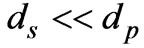 ). Assuming a simple plane wave excitation (at a wavelength l >> dp or ds), the magnitude of power transmission coefficient across electrically-thin (that is,
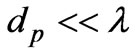 ) window due to the test card can be written as [5]:
  where,
  is the voltage reflection coefficient at the surface of the plastic card, which can be deduced as:
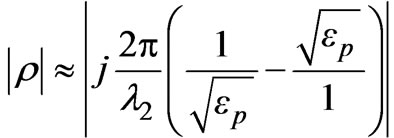 (1)
(1)
where  with
with  being the dielectric constant of the plastic material and f is the frequency of EM excitation. When the embedded set of grid-frames comes in the EM excitation zone while swiping,
  would get modified or perturbed. This perturbation can be specified in terms of power losses suffered by the EM wave passing through the plastic card and encountering the EM material, which is assumed of good conductivity/high-μ characteristics.
Also, the embedded grid-frames are of small size (area) in relation to the area of the plastic card and are electrically thin. Correspondingly, the modified (perturbed) value of  can be written as:
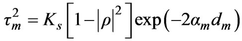 (2)
(2)

Figure 1. Embedding a set of frames of EM material in a standard plastic card. (EMM: Embedded EM material). Front side: 1) Issuing organization logo; 2) Hologram/ photograph; 3) EMV (Europay MasterCard, Visa) chip; 4) Card number; 5) Expiry date; 6) Cardholder name; and 7) Card brand logo

Figure 2. Excitation of the test card with microwave energy
source where the subscript m implies the embedment being present,  is the attenuation coefficient exclusively caused by the embedment and Ks is a scattering (power) loss coefficient due to the finite size of the embedded grid structure facing the EM radiation. Further, the attenuation coefficient (
 ) can be explicitly written as:
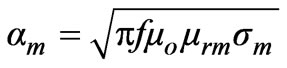 nepers/meter(3)
with f being the frequency of microwave excitation in Hz. Further,  is the free-space permeability (
 × 10-7 H/m) and
  and
and  S/m denote respectively, the relative permeability and the conductivity of the embedded material. Hence, it follows that:
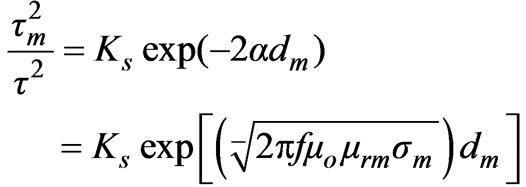 (4)
(4)
Therefore, in order to realize a good resolution of sensing the attenuation caused by the embedment (at a given frequency of operation), it is suggested to use a good conductivity plus high-μ characteristics material in making the embedded grid-frames.
Further, the embedment size (area = Am) will implicitly decide the constant, Ks. That is, Ks is a function of  and
and . The thickness (
 ) of the embedded gridframes can be chosen almost film-like without significantly altering the thickness (
 ) of the plastic card, which is set by existing standards. Therefore, the value of
  is a design parameter to be optimized.
3.1 Improvising Binary Encoding via Vertically/Horizontally Formatted Grid
Structure of Embedded Material As indicated before, suggested here a novel method of improvising a binary logic in the embedded set of EM material introduced within the plastic sheet. The method of approach is as follows: Each grid-frame is constructed with the test EM material in film/foil-like structure. It is taken in two forms: 1) A vertically-stacked stripes closely arranged to form a vertical grid structure as shown in Figure 3(a); and 2) a horizontallystacked stripes closely arranged to form a horizontal grid structure as shown in Figure 3(b).
Further, a set of vertical and horizontal grid-frames of Figure 3 can be embedded in the plastic sheet side-byside so as to form a binary logic as illustrated in Figure 4.
Suppose the microwave excitation is set to a linear polarization, vertical (VP) or horizontal (HP). Then, the corresponding transmission coefficient of Equation (4) in the presence of a grid-frame gets modified as:
 (5)
(5)
Or,
 (6)
(6)
Equation (5) applies to the transmission across the card when a vertically-polarized EM wave faces parallel grid structure and  is the corresponding attenuating parameter. Likewise Equation (6) is valid when the same vertically-polarized EM wave traverses the card and faces the horizontal grid structure, which poses a corresponding attenuating parameter of
 .
.
3.2 Designing and Testing a Concept Unit
Consistent with the concept described, different sets of test cards (of standard size as indicated in Figure 1) are designed and fabricated. These sets correspond to using different EM materials in making the grids. Specifically,
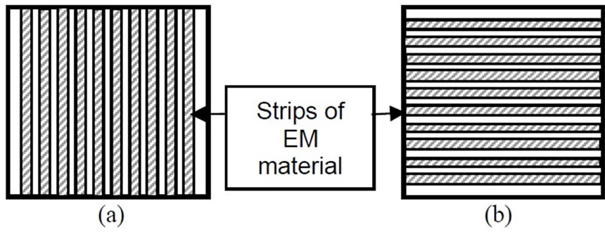
Figure 3. EM material conceived as film/foil of grid-frames for embedment in the plastic card. (a) Grid-frame of vertically-stacked strips and (b) Grid-frame of horizontallystacked strips

Figure 4. Emulation of a binary logic with vertical (V) and horizontal (H) grid-frames of EM material. Examples: (a) Logic 01010 and (b) Logic 11001

Figure 5. (a) High and (b) Low transmissions of a vertically-polarized EM wave traversing through vertical and horizontal grid structures, respectively
high-μ material and high-conductivity materials (copper and aluminum) are used.
The microwave setup illustrating the excitation of the test card and sensing the transmission coefficient are illustrated in Figure 6. As shown, the test card embedded with an EM material is illuminated with microwave radiation from a source and the corresponding transmission coefficient is measured. The recommended frequency for this operation is the license-free ISM band 2450 MHz. In the present study, however, for the purpose of demonstration a 10 GHz (X-band) source is used. But, relevant excitation/sensing considerations remain unaltered in using ISM 2450 MHz without any loss of generality.
Further illustrated in Figure 7 (photograph) is a test card embedded with high-μ material grid-frames in alternate grid formats (of vertical and horizontal structures) set to form the logic of (1, 0, 1, 0).
4. Test Results: Measured Data on Sensed RF/Microwave Signals versus Test Cards Used
Different sets of test cards described earlier (having varying area of cross-sections with plain and gridformatted structures) are subjected to testing. The measured results on microwave signal (power) attenuation due to the presence of embedded test EM materials versus the size of these materials are presented in Tables 1 to 3.
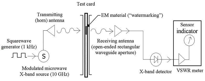
Figure 6. Laboratory set-up of microwave-plumbing for test card excitation and “watermarking” detection

Figure 7. Photograph of the test card embedded with high-μ material in alternate grid formats (vertical and horizontal). H and V depict the (1, 0, 1, 0) logic expected with a vertically-polarized EM transmission (across a verticallypositioned test card being swiped)
5. Encoding-Improvised Test Card Using Grids with Vertical and Horizontal Strips
Next, a test card having a set of four high-μ grids of vertical and horizontal strips as shown in Figure 8 is considered. Each grid frame used is dimensioned to be about 0.75 cm × 0.75 cm. As this card is swiped across the slot/groove, the measured microwave power level (in dB) depicting the encoding due to the embedded sheets are indicated in Figure 8.
6. Discussion and Closure
Referring to Tables 1 to 3 and Figure 8, the following details can be inferred: As expected, the EM materials embedded in the plastic cards react differently to the EM excitation, by virtue of the associated conductivity and permeability characteristics. (See Equation (4)). In addition, vertical (V) or horizontal (H) formatted grids (of a given size) of the EM material embedment lead to distinguishable transmission response vis-à-vis the polarization of the microwave excitation incident on the grid. This feature offers distinguishing detected signal as high or low as seen in Figure 8. Hence, a binary word can be “watermarked” using an appropriate combination of vertical (MV) and horizontal (MH) grids.
Suppose a set of eight (0.75 cm ´ 0.75 cm) vertical and horizontal grids are accommodated in the card as an array depicting an eight-bit binary word. This is quite feasible with conductive ink-jet printed material and
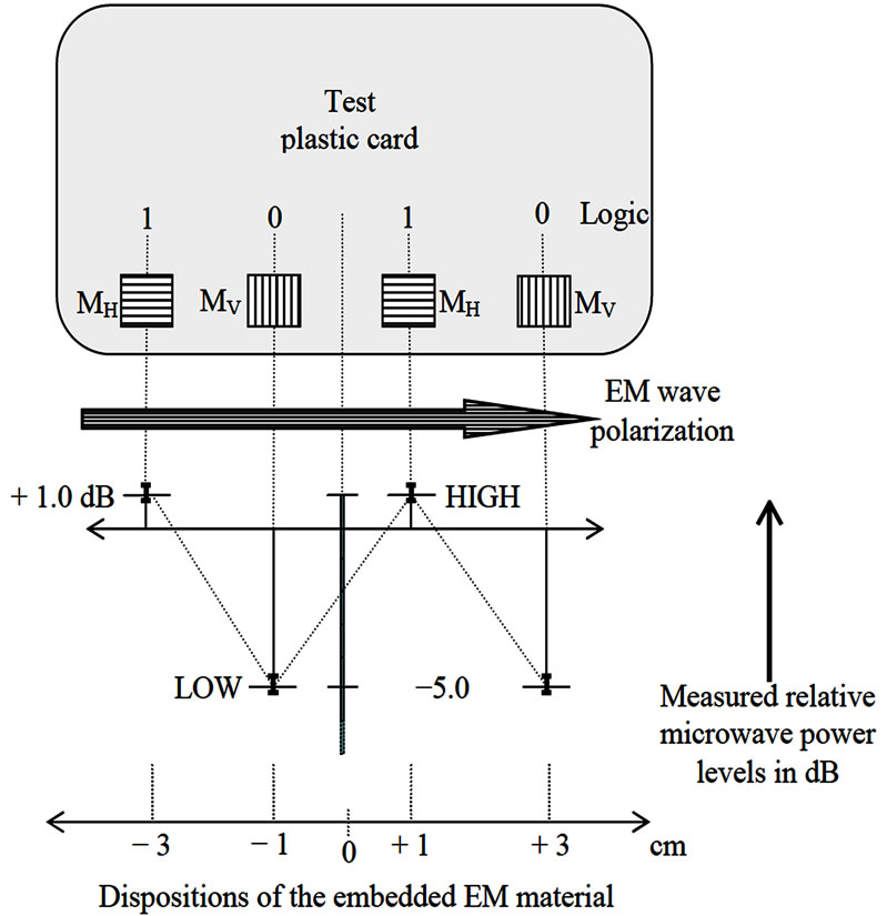
Figure 8. Measured microwave power levels (relative to a blank card) as the test card is swiped across the horizontally polarized EM excitation zone. (MH: Horizontally structured high-μ grid; and MV: Vertically structured high-μ grid)
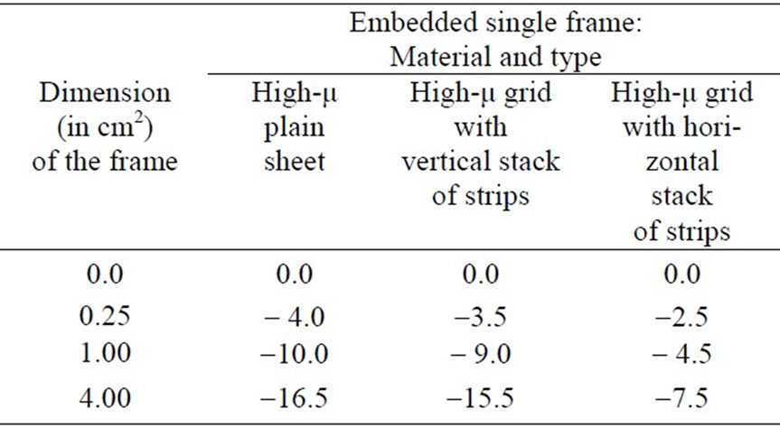
Table 1. Relative transmitted microwave power (in dB) across the test plastic card versus dimension (area in cm2) of a single frame of embedded high-μ material. (The exciting EM wave (at 10 GHz) is horizontally polarized.)
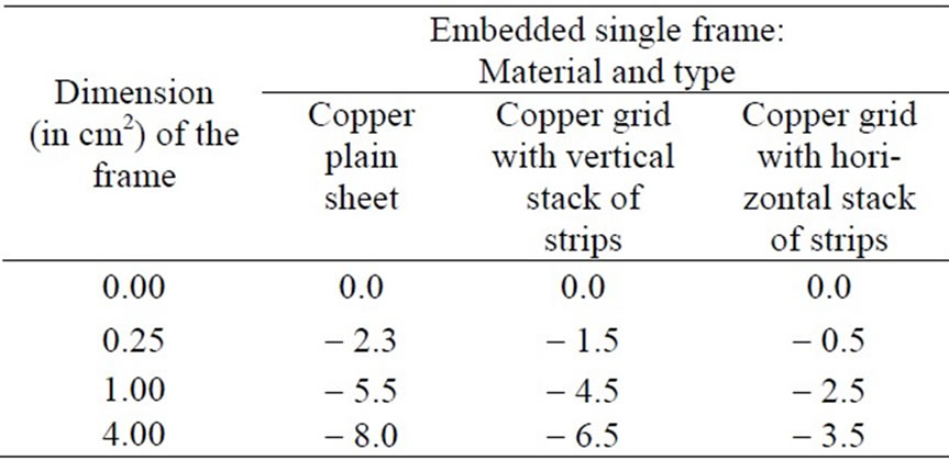
Table 2. Relative transmitted microwave power (in dB) across the test plastic card versus dimension (area in cm2) of a single frame of embedded copper. (The exciting EM wave (at 10 GHz) is horizontally polarized.)

Table 3. Relative transmitted microwave power (in dB) across the test plastic card versus dimension (area in cm2) of a single frame of embedded aluminum. (The exciting EM wave (at 10 GHz) is horizontally polarized.)
processing. This would allow a set of 28 = 256 combinations of binary signatures. If narrower strips in the grid-frame are used, the word size can further be increased; however, it requires narrow field of excitation/reading warranting a careful design of microwave transceive antennas. (In the presence study, however, a simple slot in the H-plane is used and, therefore, only a resolution of four distinguishable grids is realized).
The overall observation of the results obtained supports the proof-of-the-concept and indicates the feasibility to enhance the security feature of plastic cards with the proposed “watermarking” strategy. With this additional/overlay layer of security in the cards, the buried “watermarking” remains invisible towards fraud and duplication. Together with the state-of-the-art security technology that prevails on a plastic card (such as holography, etching, microtext, photographic perforation, UV ink, ghost images, and digital watermarking, etc.), the proposed method can be regarded as a novel addition.
This EM-material based watermarking technique offers ample scope for further studies. The following can be listed thereof:
• As indicated earlier, the binary formatting of watermarking using a passive set of grids can be conveniently fabricated using conductive ink-jet printing within the plastic card. Unlike traditional etching or photolithographic designs, printed traces and lines of about 25 m can be realized as indicated in [2]. The conductivity of ink-jet varies from 0.4 to 2.5 × 10⁷ S/m realized with silver nano-particles. This conductivity will offer required attenuation profile needed when used as the card embedment
• With the existing art of printed-antenna technology, the excitation and receiving (sensing) antennas can also be tailored to match the transceive aspects of the microwave across the test-card.
• In using low-power microwave standard ISM 2450 MHz [3] frequency source/detection methods can be adopted. Compatible RF transceivers available as surface-mounted modules for ISM 2450 MHz applications can be adopted for the present work. Such modules are also optionally available with integrated antenna. They are designed for control and industrial automation purposes. ADC capabilities are also built in.
• The superimposed microwave illumination will not interfere with 125 kHz HF illumination used in certain card-reading systems. Further, the proposed design can be introduced as a part of card-swiping unit without cross-interfering with magnetic stripe and/or chip-card processing electronics.
• Though binary formatting of watermarking indicated here uses a passive set of metallic grids, it may be possible to make such grids semi-active with a set of vertical and horizontal IC diodes, (which can be biased via metal contacts at the rim of the card during the swiping mode from a DC source made available in the card swiping unit). These biased diodes can emulate programmable grid structures as discussed by Neelakanta et al. in [8]. That is, depending upon the ON-OFF states of the diodes, the binary format can be dynamically changed. This provides additional security to the card, inasmuch as the binary ID format can be preprogrammed and changed dynamically. Such diode-based system can also be a part of any chip-embedded plastic cards.
• This is a noninvasive strategy and almost non-lineof-sight method.
• Larger the size of the sheets used, more will be the output signal, that is, more sensitivity.
• It is a “passive” method in the sense that it uses simple EM materials.
• The design optimization is aimed at maximizing the signal output and improving the sensitivity of the system. The following considerations are implied:
• Location of transmitter and receiver modules with respect to the card slot: With the availability of surface-mounted devices, this consideration can be comfortably engineered in a compact and acceptable form.
• Transmitter/oscillator power: The oscillator can be set in sleeping mode (with the power switched off) and can be made active only when the card is in situ for swiping.
• The size of the grid-frames used vitally decides the sensitivity of the system and has to be optimized.
In summary, the proposed EM-material based invisible watermarking is a viable method and offers a prospective scope for a new security technology option for plastic card industry. As indicated, it provides two distinct aspects of security in plastic cards embedded with EMmaterial based watermarking: 1) The system first identifies/detects the presence of the embedded material. Any forged card with the absence of such buried material will be rejected; and, 2) with the vertical/horizontal grid structures, inclusion of encoding/decoding of a binary word is also feasible. Further, a crisscross formatted array of the test EM materials can be suitably tailored for binary encoding/decoding with dual/circularly polarized excitations. More studies in this direction are open questions and are in progress. 3) To the best of the authors’ knowledge no similar idea and/or implementation of the concept indicated in this work has been deliberated in open literature. 4) The security features in plastic cards that currently exist do not per se are based on concealed EM material-specific binary signature described in the present work. The “watermarking” of the type indicated here is not visibly present and if tampered with, will not authenticate when the card is swept in the microwave set up improvised. As such it offers additional security to the card more than the available (security) features on the card. 5) Improvising this new feature is not expensive and may not add appreciable cost to the existing plastic cards. 6) It is therefore aptly suited for commercial exploitation since there is no parallel competitive system available. 7) The system described here is largely a proof-of-concept design. More rigorous theoretical study can be directed towards design optimization especially in devising more number of vertical and horizontal EM stripes so as to obtain larger size of binary word towards authentication and for covering more number of cards.
REFERENCES
- P. S. Neelakanta, “Handbook of electromagnetic materials – Monolithic and composite versions and their applications,” FL: CRC Press, Boca Raton, 1995.
- R. Rida, L. Yang, R. Vyas, and M. M. Tentzeris, “Conductive inkjet-printed antennas on flexible low-cost paper-based substrates for RFID and WSN applications,” IEEE Antennas and Propagation Magazine, Vol. 51, No. 3, pp. 13–23, 2009.
- ISO Standard 18000–Part 4: Air interface communications at 2.45 GHz.
- F. Ros, J. Borla, F. Leclerc, R. Harba, and N. Launay, “An industrial watermarking process for plastic card supports,” Proceedings of IEEE International Conference on Industrial Technology (ICIT’06), Mumbai, pp. 2809– 2814, 15–17 December 2006.
- S. Ramo, J. R. Whinnery, and T. V. Duzer, “Fields and waves communication electronics,” Wiley Eastern Private Limited, New Delhi, 1995.
- A. F. Harvey, “Microwave engineering,” Academic Press, London, pp. 601–605, 1963.
- H. Jasik, “Antenna engineering handbook,” McGraw-Hill Book Corporation, New York, Chapter 32, pp. 35–40. 1961.
- P. S. Neelakanta, A. K. Stampalia, and D. DeGroff, “An actively-controlled microwave reflecting surface with binary pattern modulation,” Microwave Journal, Vol. 46, No. 12, pp. 22–36, 2003.