Int'l J. of Communications, Network and System Sciences
Vol. 5 No. 6 (2012) , Article ID: 19652 , 10 pages DOI:10.4236/ijcns.2012.56040
Hybrid Uplink-Time Difference of Arrival and Assisted-GPS Positioning Technique
Electrical and Electronics Engineering Department, Faculty of Engineering, Assiut University, Assiut, Egypt
Email: zahhad@yahoo.com
Received April 19, 2012; revised May 10, 2012; accepted May 18, 2012
Keywords: A-GPS; Hybrid Positioning System; Mobile Positioning
ABSTRACT
A hybrid positioning system is merely one in which multiple systems are used for positioning purposes. This virtually always, though not necessarily, includes Global Positioning System (GPS) as it is the only global positioning network currently. Combination of mobile network and GPS positioning techniques provide a higher accuracy of mobile location than positions based on a standalone GPS or mobile network based positions. High accuracy of mobile position is mainly essential for emergency, military and many other location based services such as productivity enhancement, entertainment, position-based advertising, navigation, asset management and geographic information access. Assisted GPS, also known as A-GPS or AGPS, enhances the performance of the standard GPS in devices connected to the cellular network. This paper introduces a new hybrid technique for mobile location determination utilizing Universal Mobile Telecommunication System (UMTS) network, Mobile Station (MS) and GPS positioning characteristics. Different positioning techniques are chosen according to positioning parameters. The minimum required number of UMTS base stations, location measurement units and GPS satellites are calculated in this paper. The required number of GPS satellites is reduced from four satellites to three ones while using three dimension positioning and from three satellites to two ones at two dimension positioning. Moreover, MS receiver main functions including both network and GPS received paths to achieve output assisted data are discussed. In this paper many drawbacks such as indoor positioning, receiver high power consumption, delay in first time to fix position, low position accuracy as well as large number of required satellites and base stations are improved.
1. Introduction
There are a lot of vital applications based on mobile user location concerning both civilian and military services. Positioning accuracy plays an important role in achieving such applications. In literature [1-5] many methods of mobile user positioning in UMTS network have been introduced; each has its fundamentals, requirements and levels of accuracy. Cellular positioning can be categorized into two main techniques:
1) Network-based cellular location positioning;
2) Mobile-based cellular location positioning.
Network-based cellular location positioning technique depends on network structure and network equipments to calculate locations of mobile subscribers. A lot of methods are developed to achieve this target with different positioning accuracies such as: Cell Identifier plus Round Trip Time (CID + RTT), Enhanced Cell Identifier plus Round Trip Time (ECID + RTT), Pilot Correlation Method (PCM), Observed Time Difference of Arrival (OTDOA), Uplink Time Difference of Arrival (UTDOA) and Network Assisted Global Navigation Satellite Systems (NA-GNSS). The major advantage of this technique is a minimization of the impact on terminal implementation. Thus, time to market of such positioning technology can be substantially improved through avoidance of the user terminal replacements. Logically, network-based positioning is preferred by network operators. Thus, in this paper network-based solution is implemented.
Mobile-based cellular location positioning technique depends on mobile equipment circuits to calculate locations of mobile subscribers. This type of positioning aims to minimize the network involvement in the position estimation process. A lot of methods are developed to achieve this target with different positioning accuracies such as: Cell Identifier plus Signal Strength (CID + Signal Strength), Delay spread-based hybrid method and Assisted GPS (A-GPS) which can be based on mobile or network location positioning techniques.
Location based services (LBS) are the most recent and useful applications depend mainly on mobile user location. Federal communication commission (FCC) stated the required positioning accuracy for both operators and mobile manufacturers. E911 Phase II report issued in 1999 requires that all cellular operators must have location-enabled technology providing accuracy of 100 m for 67% of calls and 300 m for 95% of calls for networkbased solutions and correspondingly 50 m and 150 m for mobile-based solutions [6].
2. Positioning Techniques of Mobile Users
There are many developed positioning techniques participate in detecting location of mobile user with different accuracies. Time-biased positioning methods starting with Time of Arrival (TOA) till Up-link Time Difference of Arrival (U-TDOA) in addition to GPS positioning fundamentals are summarized in the following.
2.1. Mobile Based Time of Arrival Technique
This technique depends on the absolute time measurement of the signal which arrived from handset to base station. This measurement can be achieved using single or multiple base stations. However, this technique requires a very accurate timing reference at the mobile which need to be synchronized with the clock at the base stations. Clearly, this solution is very difficult to achieve, as having an accurate and synchronized clock in the mobile is a difficult technical challenge and would again result in increased cost and size of the mobile handset.
2.2. Mobile Based Time Difference of Arrival Technique (TDOA)
Secondary network of base stations at fixed locations are acting as dummy handsets in the TDOA method. The mobile handset and a nearby dummy base station both capture a portion of the forward link signal from the actual base stations at a synchronized time period. Thus, the time difference of the signal arrival at the mobile and the dummy station is known. Since the coordinates of the dummy stations and the actual network base stations are known, this gives the distance between the mobile and the actual base station. Performing three such measurements with three different actual base stations, the position of the mobile can be found using the triangulation method. This technique requires considerable change in the handset software along with additional hardware installations.
The mobile measures the arrival time differences of at least three pilot tones transmitted by three different cells. By intersecting hyperbolas the mobile’s position can be estimated. This method requires all the processing to be done at the handset and then requires the location estimated to be transmitted to the system on the reverse link. Thus, handset costs and bulk will be increased due to such needed additions to meet the synchronization and estimation requirements [7].
2.3. Network-Based Uplink Time Difference of Arrival (U-TDOA) Technique
U-TDOA technology locates wireless phones by comparing the time it takes a mobile station’s radio signal to reach several Location Measurement Units (LMUs) installed at an operator’s base stations, as shown in Figure 1. U-TDOA approach is used to enable location-based services such as emergency location, asset tracking, and mobile concierge services. The wider UMTS bandwidth coupled with significant processing gain available to network based location systems provide higher level of accuracy in UTRAN networks and in situations where other location techniques may not be able to perform well. This increased accuracy can be achieved at reduced complexity over implementations of downlink OTDOA or A-GPS. Additionally, critical for future success of network operators, the uplink TDOA method provides significant flexibility for implementation of future location service enhancements. Many methods based on signal attenuation can’t be applied in UMTS network due to the near-far effect [8].
In uplink method the processing functions to calculate user position is done in the network equipment especially location measurement unit (LMU) instead of mobile equipment processing used in downlink method. In addition, uplink method has increased processing capacity available to analyze signal information and to calculate subscriber locations. The uplink method provides increased power from 20 to 30 dB greater in processing gain than a DL-OTDOA solution through long integration times. In the DL-OTDOA system, the mobile station must make measurements of pilot signals from several sites, one by one, while still providing the other mobile station functions. The DSP processors of many LMUs work simultaneously to locate a single mobile subscriber. So, downlink method latency problem is solved. Simultaneous location of many subscriber units can be detected using U-TDOA approach utilizing increased power solution. Also, this solution includes acquisition of location information from many more distant location receivers.
2.4. Global Positioning System (GPS)
Global positioning system is based on satellite communication which comprises three main steps:
Identification of satellites: Receivers must identify satellites used in measurements. Receiver selects a subset of at least four satellites that are actually considered during the measurements depends on the geometry between each satellite and receiver.
Range measurements: Code phase ranging and carrier phase ranging are common methods for range measurement in GPS system depending on the required accuracy and application in use.
Position calculation: Accurate geometric position is calculated by compensating certain error budget of pseudo range obtained in the previous step. Satellite positioning using GPS suffers from many short comes as positioning start time latency, environmental limitations (i.e. indoor, satellite out coverage) and high power consumption at GPS receivers. These defects can be overcome using cellular positioning techniques whether using network based or mobile based cellular positioning technique. Among these techniques, Differential GPS (DGPS) is one of the most efficient techniques.
The principle of D-GPS is to observe the pilot signal from the satellite at a fixed well-known position, reference station, and to determine the difference between the measured range and an approximation of the true range derived from the known position of observation. This difference represents the correction value for GPS receivers nearby the reference station. As shown in Figure 1, reference station permanently observes all visible satellites. From these observations accurate range and pseudo range measurements are obtained according to the following two equations respectively.
 (1)
(1)
 (2)
(2)
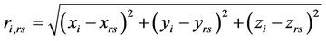
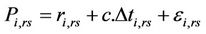
where,  is the range between the accurate position
  of the reference station and the position
  of the i-th satellite, which is derived from the ephemeris contained in the navigation message and which might be subject to slight deviations from the satellite’s true position owing to perturbing forces. Whereas
  is the measured pseudo range,
  is the time offset between the clocks of the satellite and receiver.
  represents ionospheric and tropospheric refraction, multipath propagation, and other error sources. The reference station calculates the difference between true range and pseudo range for each visible satellite and broadcast the estimated correction data via wireless network to the nearby mobile receiver. D-GPS is not only an efficient means for significantly improving the accuracy
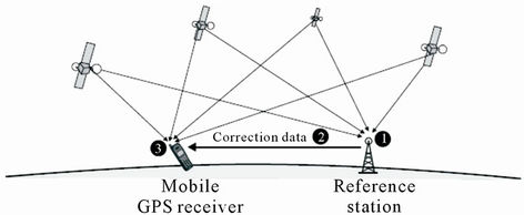
Figure 1. Differential GPS overview.
of position, but also for reducing the Time to First Fix (TTFF).
3. Assisted GPS Positioning Technique
Assisted GPS (A-GPS) is an extension of the conventional Global Positioning System (GPS) which increases start-up sensitivity by as much as 25 dB relative to conventional GPS and reduces start times to less than six seconds as discussed in [9]. A-GPS technology follows the principle of D-GPS with additional assistance data from cellular network which is used to reduce acquisition time, enhance positioning accuracy and provide communication facilities. By integrating GPS into cellular networks, the GPS positioning is supported by additional D-GPS reference stations as integral part of the cellular infrastructure and by additional signaling procedures between network and terminal. The resulting positioning method is commonly known as A-GPS, as discussed in [10]. Assistance data is done using variety of UMTS mobile network positioning types such as AOA, TDOA, O-TDOA [11] and UTDOA or in GSM mobile network as introduced in [12]. It was found that an AGPS receiver provided a 13 dB improvement in acquisition sensitivity over an HS receiver and a 20 dB improvement over a conventional GPS receiver as proven in [13]. A-GPS has the following improved prosperities compared to standard GPS method:
· Higher position accuracy.
· Lower power consumption at GPS receiver terminal.
· Higher receiver sensitivity.
· Lower TTFF and acquisition time.
· Fewer number of satellites needed in position detection.
As shown in Figure 2, A-GPS requires the following infra-structure components:
GPS receiver unit at target mobile terminal to be capable of acquiring assistance data from both satellite and cellular network.
Reference stations inside the cellular infrastructure for calculating correction data and compiling the raw material for assistance data as shown in [10]. One reference station for areas with a radius of approximately 200 km is sufficient as proven in (3GPP TR 25.850).
Serving Mobile Location Center (SMLC) is used to coordinate positioning process. Signaling is performed between SMLC and both reference station and target terminal especially in point to point signaling.
The A-GPS modes of operation are summarized in the followings:
1) Mobile Station Assisted (MSA) mode—In this mode, the A-GPS has capable device receives acquisition assistance, reference time and other optional assistance data from the A-GPS server. With the help of these data,
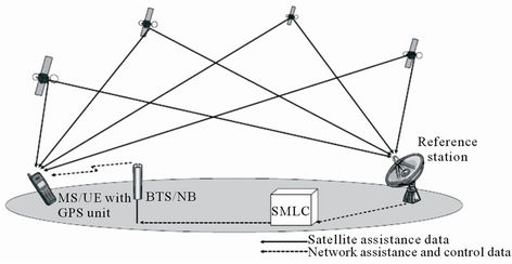
Figure 2. Conventional A-GPS infrastructure.
the A-GPS device receives signals from the visible satellites and sends the measurements to the A-GPS server. The A-GPS server or LMU calculates the position and sends it back to the A-GPS device [14].
2) Mobile Station Based (MSB) mode—In MSB mode, the A-GPS device receives ephemeris, reference location, reference time and other optional assistance data from the A-GPS server. With the help of these data, the mobile equipped with GPS receiver receives signals from the visible satellites and calculates the target position in mobile station as discussed in [15].
4. The Proposed Hybrid Positioning Technique
In this section the proposed hybrid A-GPS positioning technique based on U-TDOA cellular position assistance is developed. It is based on the integration between GPS data and cellular network infrastructure based on UTDOA assisted data. This yield to accurate positioning of mobile user and to overcome short comes of both techniques while being used individually. From Table 1, it is observed that GPS is the most accurate positioning technique with position accuracy (5 - 30 m). Moreover UTDOA is the most accurate positioning technique depending upon cellular based networks with approximately less than 50 m accuracy. So, the integration between the two methods produces highly accurate positioning technique valid for most environments and with a higher performance than that used by each technique in standalone mode.
4.1. Time to First Fix Using Hybrid Positioning Technique
Conventional GPS consumes more than one minute to get first reading of mobile user location. Although each GPS satellite transmits at the same frequency, the signals are not observed at the same frequency because of the Doppler shift caused by the satellite motion, the receiver motion and any frequency offset in the receiver reference oscillator. Receiver would scan all possible frequencies till reach the accurate frequency. Also, GPS receivers find
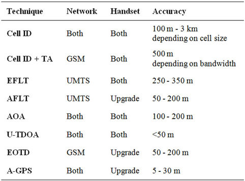
Table 1. Comparison between positioning techniques.
a correct code delay for the correlators to generate a correlation peak within about more than thirty seconds. This delay is named frequency/code delay search space [16].
The expected Doppler frequencies can then be computed and the frequency delay search space is reduced. The correlation peak varies with frequency as a  function:
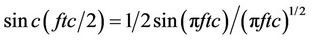 (3)
(3)
where f is the frequency error and tc is the coherent integration time, as shown in [16]. Also, the Doppler Effect result from receiver speed is:
 (4)
(4)
Network assisted data is necessary to have at least a rough a priori position and a priori time and satellite orbits. A-GPS is mainly used to reduce the frequency and code-delay search space. To reduce the frequency search space it is necessary to have at least a rough a priori position and a priori time and satellite orbits. The expected Doppler frequencies can then be computed. Similarly, to reduce the code-delay search space, it is necessary to have a good a priori position and a priori time. Where, the a priori time must be known to better than 1 ms which is known as fine-time assistance else it is a coarsetime assistance. By these means of frequency/code search space reduction, TTFF will be reduced significantly. Practically, improvement in TTFF by about 30% - 45% at –142 dbm signal strength within 250 and 500 µs timing accuracy respectively is proven in [17].
4.2. Elements Required in Hybrid System
Four satellites are needed at least to determine the three dimensions of the mobile equipment position in conventional GPS. The four satellites are used to determine the following position parameters (xi, yi, zi, t) where x, y and z are the three dimensional cartezian location coordinates, i indicates the satellite number and t is the synchronization time error.
Each satellite has its position detection sphere which introduces one position equation. By solving such four equations, the four mentioned unknowns can be determined and mobile equipment position is detected. By suggesting distance between the i-th satellite and the receiver position as Ri, satellite position (xi, yi, zi) and receiver position (X, Y, Z) and receiver time clock error t, Equations (5) represent the four satellites equations adopted for position determination. By solving these equations, the four unknowns X, Y, Z and t can be determined using Equation (5).
A-GPS technique already has network GPS receivers, included in NodeB or separated, which are synchronized with satellites. Since the time delay data (t) can be determined using mobile network, we need only three satellites for mobile position determination instead of four satellites had used in conventional GPS. The accuracy of position determination depends upon the code used in calculations. In case of neglecting Z-coordinate “altitude of the mobile receiver”, we will need only three satellites to get (X, Y, t) unknowns of the receiver position in conventional GPS positioning. Whereas, the two satellites are sufficient to detect two-dimensional receiver’s position in hybrid positioning.
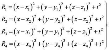 (5)
(5)
4.3. Choice of Most Accurate GPS Satellites
There are about 31 satellites catering to the worldwide GPS systems. In A-GPS as we need only four GPS satellites to determine mobile user position, the best four satellites should be chosen. GPS signal strength is the main factor which is used to choose the best satellites needed for measuring process. There are several methods to measure GPS signal strength. The most common method used by civilians is the ones related to telecommunications, including the Received Signal Strength Indication (RSSI) based on the IEEE802.11 protocol. On the other hand, many GPS manufacturers build their own GPS algorithm to create code for calculating GPS signal strength. By the same way for two or three needed GPS satellites as mentioned in Section 4.2, choice will be according to GPS signal strength. Received signal strength is used to select the most accurate NodeBs/LMUs required in location determination process. The higher the RSSI number, less negative, the stronger the received signal.
4.4. Hybrid Positioning Technique’s Parameters
As mentioned in Section 2, each of the mentioned positioning technique has its advantages and drawbacks. Positioning techniques are classified according to the following main parameters: 1) Accuracy; 2) Latency; 3) Call state; 4) Environment; 5) System loading.
Table 2 illustrates the used suitable positioning technique according to the main positioning parameters. Suitable positioning technique such as A-GPS, stand alone GPS or U-TDOA, is selected according to the location based service application needed.
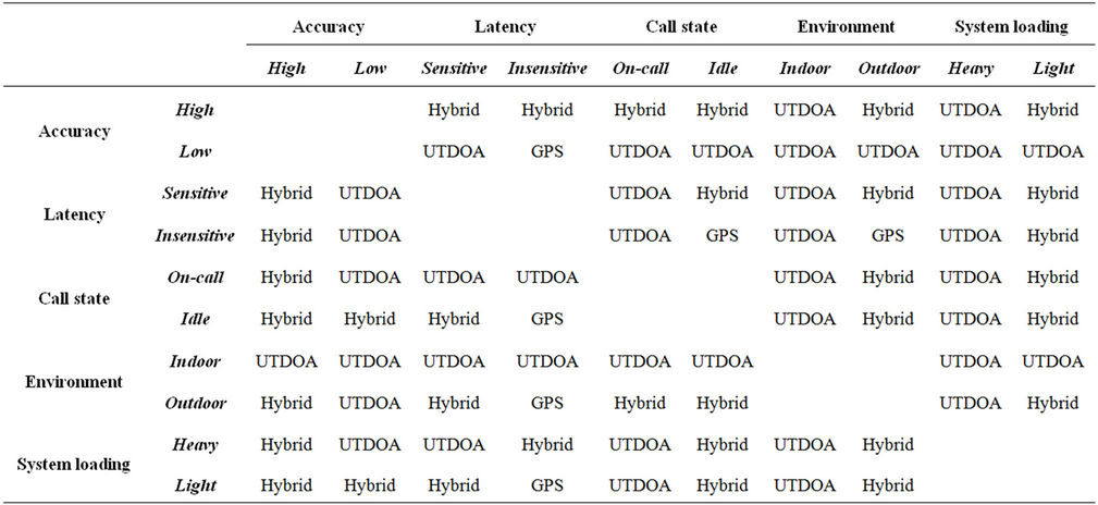
Table 2. Positioning parameters versus positioning technique.
· Mobile tracking applications: The major property of these applications is latency sensitive, so stand alone GPS isn’t a suitable positioning technique. Accuracy is the second parameter in these applications so, if application need accuracy less than fifty meter, then hybrid technique is being used. Otherwise U-TDOA will be the most suitable technique here.
· Emergency applications: These applications require high accuracy without time delay. Then, hybrid method is selected in outdoor applications whereas UTDOA will be more precise in indoor applications.
· Commercial advertisements and general information: Most information like weather, traffic, advertisements are highly used in city center and crowded regions. So, system loading is the most positioning parameter that should be taken into consideration. So, U-TDOA is the most suitable positioning technique for heavy system loading.
4.5. Secure User Plane Location Protocol
In order to decrease system loading problem especially in crowded locations and city centers secure user plane location protocol is used instead of Radio Resource Control (RRC) protocol which is used by UMTS mobile network as discussed in [9]. Secure User Plane Location Protocol (SUPL) is a network layer based on IP technology that was developed to support Location-Based Services (LBS) for wireless communications. SUPL employs available user plane data bearers for transferring location information, GPS assistance data, and for carrying positioning technology-related protocols between a SUPL Enabled Terminal (SET) and the mobile network. This developed protocol permits hybrid developed technology to be used in heavy loaded networks’ systems. SUPL provides low cost and complexity in network implementation than conventional RRC protocol which is based on control plane.
5. Network Elements and Positioning Sequence
twork equipments used in mobile location determination using hybrid technique is called Position Determination Equipment (PDE). PDE is mainly consists of Location Gateway (LG), Serving Mobile Location Center (SMLC), Location Measurement Unit (LMU) and NodeB [16]. As shown in Figure 3, plenty of network elements are needed within hybrid positioning technique. For more arrangement and decrease among network components the following actions are suggested:
a) Integrate each LMU into corresponding NodeB with common processor, as shown in Figure 4. Processors are mainly responsible for network management and provide a centralized pool of digital signal processing resources used in location calculation.
b) Integrate SMLC into corresponding RNC/BSC.
The procedure of detecting mobile location using hybrid positioning technique can be logically summarized into the following steps:
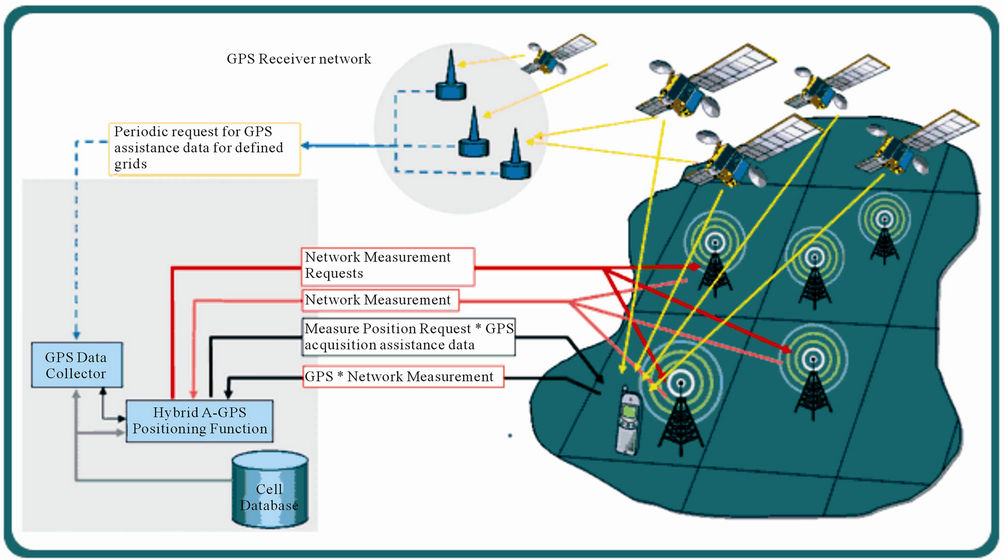
Figure 3. Hybrid GPS_UTDOA network platform.
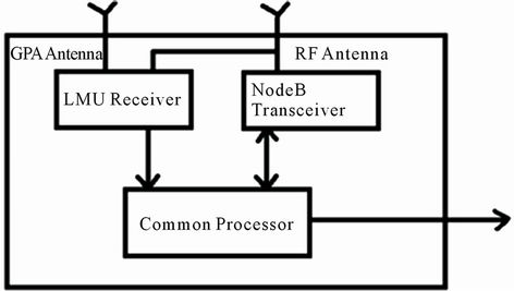
Figure 4. Common processor LMU and NodeB.
1) MS sends request to LG including serving NodeB, cell ID, associated frequency, code, communication parameters and authentication.
2) LG receives the location request from MS, check authorization and validation.
3) LG sends the request to the SMLC which serve the MS and controls the entire positioning process, including allocation of resources, evaluation of timing measurements, and calculation of position fixes.
4) SMLC receives the request and selects the nearest LMUs for serving MS from a list of LMUs included in SMLC database. The database contains the latest data of satellite locations and motion parameters related to each LMU.
5) LMU receives GPS navigation message periodically and extract Doppler shifts, pseudo ranges and navigation messages, correction data and sends these data to SMLC.
6) SMLC receives satellite data from LMU and periodically or on demand evaluates satellites’ locations and update current list of assisting satellites’ IDs, Doppler shift and pseudo range domains appropriate for each LMU.
7) SMLC send the determined GPS data to LG which redistribute its location parameter to MS to be able to detect satellite rapidly and decrease TTFF.
8) SMLC request location related data from all LMUs selected to cooperate in providing measurements.
9) LMUs respond to SMLC by the extracted, measured and obtained data related to the MS of interest.
10) LG receives the GPS data measured by the MS GPS receiver and sends them to the SMLC.
11) SMLC calculates the optimal integration of MS GPS data with the LMU measurements which represent the most accurate location of MS and send it to LG.
12) LG receives location determination from SMLC and send it to the MS as a response of original location request.
Positioning requests by external applications can be done using the same steps from Step 4 to step 11. Then, the calculated position is sent from LG to the requester such as application server. Figure 5 shows the flow chart of the main functions and their procedure of the hybrid UTDOA and A-GPS technique.
6. Modified MS Receiver Architecture
Mobile station main components are shown in Figure 6. Bidirectional antenna 1 is adapted to receive both UMTS and GPS signals. Duplexer 2 allows bidirectional communication, transmit and receive, into single channel. Electrical switch 3 is implemented to switch between GPS signal and 3G signal. Low noise amplifier 4, first band pass filter 6, first mixer 10 and second band pass filter 14 are the first part of receiver of UMTS signal which are used to down convert the RF signal into intermediate frequency band. The IF band signal represents the first step to get the base band source signal.
By the same way, the path contains 5, 7, 11 and 15 circuits is used to down convert GPS radio signal into intermediate frequency band. Dual phase locked loop PLL 9 controls the local oscillators 12 and 13 at specific reference frequencies to down convert both UMTS and GPS radio signals. Clock generator 8 extracts clock from UMTS signal, as LMU sends it via Node B to MS thus GPS, Node B, LMU and MS will be synchronized. IF Demodulator 16 is the first part of the Application Specific Integrated Circuit (ASIC). This provides the second stage of IF to base band down conversion, sampling and A/D conversion as discussed in [13]. Second switch 17 is analogues to switch 3 and they controlled by the same controller unit to separate CDMA and GPS received signals at radio and intermediate frequency bands.
As explained before, LMU provides GPS data to MS via Node Bs. So, this data will be extracted by MS using Decoder 18 to extract almanac, Doppler shift, etc. for each of GPS satellites. The Doppler frequency Fd that is recognized by decoder 18 is added to local oscillator Fif to control the GPS mixer 19. This mixer is used to convert IF signal to base band signal as the last stage of base band signal down conversion in GPS received path. The output of automatic gain control AGC 21 circuit is fed to analog to digital converter A/D 22. The output of the A/D consists of the (I,Q) in phase and quadrature components as a first and second output digital streams respectively. The digital streams are fed to the digital signal processor DSP 24 to produce the required pseudo measurements. Buffer 23 is used to store data streams in case of the rate of flow of data is faster than that of DSP rate of processing. Pseudo ranges are sent via MS transmitter to LMUs to calculate the user position accurately.
7. Position Calculation
Location determination and measurements using hybrid technique are classified into two main measurements.
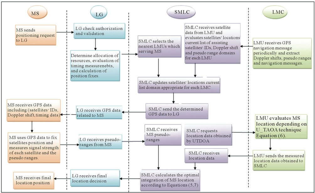
Figure 5. Flow chart of main functions and their procedures of hybrid UTDOA and A-GPS technique.
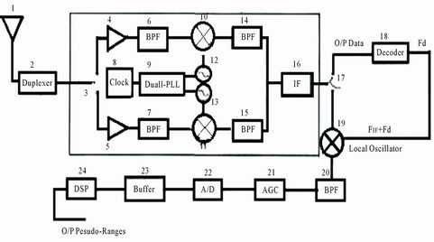
Figure 6. Block diagram of MS receiver.
7.1. Position Calculation Using U-TDOA Technique
This type of measurement is one of distance related measures where distance is calculated through mobile network. Measurements are based mainly on the difference between two Times of Arrivals (TOA) for two distinct signal receptions at least. MS is a common transmitter for signal to the distinct and different LMUs as receiving stations positioned at locations XR1 and XR2 respectively. TDOA technique is directly related to the difference in TOA at different receivers. This leads to difference in signal propagation distances (DR1, and DR2) at receivers.
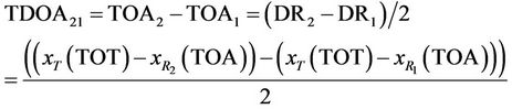 (6)
(6)
where c is the propagation speed of RF signal,  is the three dimensional vector coordinates of receiving position at time of signal arrival. Determination of transmitter’s location doesn’t require knowledge of the TOT common epoch at which MS signal was transmitted. Then synchronization between MS and NodeB isn’t necessary from Equation (6) it can be deduced that at least two NodeBs are required to enable U-TDOA technique to calculate the position of mobile terminal.
7.2. Position Calculation Using Hybrid Positioning Technique
The optimum estimation of mobile user location depends on the location-related information available which is extracted from the following sources:
1) Measurement of received signal characteristics.
2) Collateral information that indicate the relative probability of MS position.
Using Bayes probability relation the relative probability of occurrence of measurements under condition of a priori state condition is expressed as:
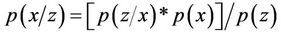 (7)
(7)
where x is the state vector of location parameters, z is a vector set of location measurements and  represents the probability of the state vector components are evaluated for x under condition that the observations have the values of measurement values z. Whereas
  represents the probability that the values of vector z would be observed under condition that the state variables are of the values in x.
  is the marginal probability that the state values of x occurred. Whereas,
  is the total probability of occurrence of measured parameter values for the observation vector z. The jointly combined probability of independent data elements are the product of the probability of independent data sets alone [18]. Using the proposed system, the data of various types from diverse sources, satellite and mobile network, integrates statistically independent data. Then, the probability product relation is accumulated as a sum of “log likelihood”. Sum of probabilities will introduce higher location probability than product formula and higher results can be obtained. This way leads to accumulation and integration between both GPS and UTDOA techniques to get higher positioning technique than obtained from standalone technique.
8. Conclusion
There are many positioning techniques based on mobile stations, network stations or GPS. Each technique has its specific advantages and drawbacks. Hybrid techniques are applied to overcome drawbacks of some positioning techniques by using advantages of others. In this paper, hybrid UTDOA and A-GPS positioning technique In UMTS network has been introduced. Network elements’ functions and its procedure for location determination are explained. Advanced GPS receiver structure to achieve procedure requirements and generate the required pseudoranges is implemented. The developed technique theoretically has the following advantages:
· Reduction of TTFF by utilizing assisted data from LMU in mobile network.
· High positioning accuracy than obtained by standalone GPS or UTDOA.
· Number of needed GPS satellites is less than that needed in conventional GPS as discussed according to two/three dimension applications.
· The optimal positioning technique such as GPS, UTDOA or hybrid is obtained depending on the positioning parameters such as accuracy, latency, call state, environment and system loading.
· Problems caused by system loading can be solved using SUPL protocol between MS and mobile network.
REFERENCES
- J. Borkowski and J. Lempiäinen, “Practical NetworkBased Techniques for Mobile Positioning in UMTS,” EURASIP Journal on Applied Signal Processing, Special Issue on Wireless Location Technologies and Applications, 2006, pp. 1-16.
- J. Borkowski, J. Itkonen and J. Lempiäinen, “Impact of UMTS Topology Configuration on Cell ID + RTT Positioning Accuracy,” Proceedings of the 15th IST Mobile Communications & Summit, Myconos, 4-8 June 2006.
- J. Borkowski and J. Lempiäinen, “Novel Mobile-Based Positioning Techniques for UMTS,” Proceedings of the 9th IEEE International Symposium on Wireless Personal Multimedia Communications, San Diego, 17-20 September 2006.
- J. Borkowski, J. Niemelä and J. Lempiäinen, “Cellular Location Technologies Supporting AGPS Positioning in UMTS Networks,” Proceedings of the 62nd IEEE Vehicular Technology Conference, Dallas, 25-28 September 2005.
- M. Abo-Zahhad, S. M. Ahmed and M. Mourad, “Map Based Intra-Cell Method for Location Prediction over UMTS Network Platform,” Journal of Engineering Science, Vol. 39, No. 5, 2011, pp. 1-26.
- 3GPP TS 25.433, “UTRAN Iub Interface Node B Application Part (NBAP) Signaling,” Version 7.6.0, Release 7.
- A. Urruela, A. Pages-Zamora and J. Riba, “Divide-andConquer Based Closed-form Position Estimation for AOA and TDOA Measurements,” Proceedings of IEEE International Conference on Acoustics, Speech, and Signal Processing, Toulouse, 14-19 May 2006, pp. 921-924. doi:10.1109/ICASSP.2006.1661120
- R.-T. Juang, “Hybrid SADOA/TDOA Mobile Positioning for Cellular Networks” IET Journal on Communications, Vol. 1, No. 2, 2007, pp. 282-287.
- P. Kashyap, A. Samant, et al., “An Assisted GPS Support for GPS simulators for Embedded Mobile Positioning,” Proceedings of SPIE-IS&T Electronic Imaging, San Diego, 2-6 August 2009.
- A. Küpper, “Location Based Services Fundamentals and Operation,” John Wiley and Sons, Hoboken, 2005.
- C. Fritsche, “On the Performance of Hybrid GPS/GSM Mobile Terminal Tracking,” IEEE International Conference on Communications Workshop, Dresden, 14-18 June 2009, pp. 1-5.
- M. D. Karunanayake, M. E. Cannon and G. Lachapelle, “Evaluation of Assisted GPS (A-GPS) in Weak Signal Environments Using a Hardware Simulator,” The ION GNSS Conference, Long Beach, 21-24 September 2004.
- D. W. Lim, “Design of an Assisted GPS Receiver and Its Performance Analysis,” IEEE International Symposium on Circuits and Systems Conference, New Orleans, 27-30 May 2007, pp. 1742-1745. doi:10.1109/ISCAS.2007.377931
- J. Syrjarinne, “Supporting an Assisted Satellite Based Positioning,” US Patent No. US7701387B2, 2010.
- 3GPP TS 25.305, “UMTS, User Equipment (UE) Positioning in Universal Terrestrial Radio Access Network (UTRAN),” Version 7.3.0, Release 7.
- F. van Diggelen, “A-GPS: Assisted GPS, GNSS, and SBAS,” Library of Congress Cataloging-in-Publication Data, 2009.
- M. D. Karunanayake, M. E. Cannon and G. Lachapelle, “Evaluation of Assisted GPS (A-GPS) in Weak Signal Environments Using a Hardware Simulator,” The ION GNSS Conference, Long Beach, 21-24 September 2004.
- R. J. Anderson and J. E. Maloney, “TDOA/GPS Hybrid Wireless Location System,” US Patent No. US7925274- B2, 2011.