Journal of Biomedical Science and Engineering
Vol.09 No.02(2016), Article ID:63731,11 pages
10.4236/jbise.2016.92006
Microwave/Thermal Analyses for Human Bone Characterization
Vinay Kumar Suryadevara1, Suyog Patil1, James Rizkalla2, Ahdy Helmy2, Paul Salama1, Maher Rizkalla1,3
1Department of Electrical and Computer Engineering, Indiana University-Purdue University Indianapolis, Indianapolis, USA
2Indiana University School of Medicine, Indianapolis, USA
3Integrated Nanosystems Development Institute (INDI), Indiana University-Purdue University Indianapolis, Indianapolis, USA

Copyright © 2016 by authors and Scientific Research Publishing Inc.
This work is licensed under the Creative Commons Attribution International License (CC BY).
http://creativecommons.org/licenses/by/4.0/


Received 5 January 2016; accepted 21 February 2016; published 24 February 2016
ABSTRACT
A novel imaging approach utilizing microwave scattering was proposed in order to analyze various properties of bone. Microwave frequencies of 900 MHz, 1 GHz, and 2.4 GHz were used during this study. This investigation’s objectives were to emphasize characteristics of abnormalities in human bones and to detect fine fractures through contrasts in bone density. The finite element method (FEM) presented here is generated from COMSOL software at different frequencies. The study identified the optimum transmission directed at the interface layers from an external microwave source. It was found that approximately 900 MHz microwave power was ideal for this application. This can be attributed to the penetration depth where the power dissipation is analyzed based on bone condition. The microwave energy was generated from an exterior antenna that was interfaced, via catheter, to skeletal bone. The power transmitted to bone was converted into thermal energy, and has led to a visible temperature distribution pattern, which reflects the bone density level, and accordingly, the type of bone under investigation. The electrical and thermal properties, including the dielectric permittivity, thermal conductivity, and heat flux absorption through the bone substance, have great implications on the FEM distribution. The boundary conditions using tangential matching of field components at the tissue-bone interface were incorporated into the finite element method. The average power from the electromagnetic fields (estimated from the Poynting’s vector, P = E*H), was assumed to be fully absorbed as heat due to the conductivity of the bone material. Furthermore, microwave energy was applied as a delta function and the thermal distributions have been analyzed in order to distinguish between normal healthy bone and bones with structural or metabolic abnormalities. The latter was emulated by different bone density to contrast normal bone anatomy. The FEM simulation suggests that thermography microwave imaging could be a good tool for bone characterization in order to detect skeletal abnormalities. This approach could be advantageous over other existing methods such as X-ray imaging.
Keywords:
Microwave, Human Bones, Simulation, FEM, COMSOL, Thermal, Diagnosis

1. Introduction
The health needs of patients, across the world, are ever-evolving and changing with each patient’s lifestyle and habits. The healthcare industry is constantly faced with new medical issues and must always be advancing in order to maximize patient care. With obesity becoming more and more prevalent across the world, serious skeletal abnormalities are presenting themselves earlier and earlier in society. Increased stress on bone, joints, and cartilage are paving the way to increasing forms of bone pathology. Taking a preventive approach to orthopedic care is vital to optimizing the prevention of ailments seen in these patients. Detecting abnormalities at earlier stages is a current challenge in orthopedics given the limited imaging modalities that are conducive for visualizing the bone’s properties. Several examples, such as subtle or micro-fractures, early neoplastic growth in bones, and micro damage to joints may not be adequately diagnosed early due to difficult visualization with the current imaging modalities. Standard of care for most orthopedic pathology consists of radiographic imaging to diagnose bone fractures, but is limited in visualizing dislocations or injuries to ligaments or muscles. Furthermore, radiographic imaging is also dependent on the size of the fracture seen. Challenging the current standard of care with new technologies may prove to be beneficial and more effective in the long-term. Therefore, research is a major key to success in this field and remaining at the forefront of research is essential for patients suffering from bone and joint injury.
In this study, we concentrated our efforts on the FEM simulation of human bones. The deterioration of bone structure, for instance, may lead to bone fragility and osteoporosis-related fractures that may occur to nearly 50% of women and 25% of men. Some of these diseases lead to long-term care and hospitalization, which is both difficult and costly for the patient. More serious sequelae, such as spinal cord damage, may result from osteoporotic spinal fractures in the elderly ultimately leading to severe long-term disability or even death due to additional complications [1] [2] . Orthopedic computer simulation may serve as a preliminary means of testing the performance of such methods within the human body. Furthermore, this investigation may enhance the study of correlated parameters such as the size of the pelvis, weight, age, gender, etc on the future occurrence of orthopedic diseases. Currently, first line imaging of bone is X-ray or CT scans. However, both of these imaging modalities expose patients to small amounts of radiation. Radiation exposure in children and pregnant women opens the door to lots of other potential pathologies in the future. Therefore, other imaging modalities are oftentimes preferred [5] .
2. Simulation Model
Electromagnetic wave transmission and interaction with biological materials plays an important role for biomedical applications. The role of electromagnetics within the human body has been emphasized and researched by investigators in recent years [3] [4] . This association can be further analyzed by absorption and scattering properties through multiple layer structures that mimic human tissue. For the purpose of this investigation, human tissue was simplified into a bilayer interface of skin (epidermal and sub-dermal layers) and bone. Additionally, the EM model incorporates power consumption from the lossy medium of human bone as waves pass through it, resulting in power losses and altering temperatures. Any noise that resulted from electromagnetic interference was neglected in the study.
The dielectric property of bone was a controlling factor in determining the temperature distribution after wave energy was applied. These properties have been studied as function of the frequency [6] in past research. Dielectric properties are subject to dynamic behavior and change with age, genetics, gender, etc. which may impact the condition of bone. As a result, the generated heat is attributed to the conductivity effect of the dielectric constant at a given frequency, as described in the heat equation created for this bilayered structure. The equations presented below, were generated using COMSOL software for FEM simulation.
The antenna’s structure, as defined by COMSOL, was enclosed in a catheter sleeve and placed adjacent to skin and bone. Figure 1 describes the structure of the multilayered composition used in this simulation. Given

Figure 1. Antenna inserted in human body part. From the left, the first layer is antenna, air, catheter, and bone material. The catheter serves as a protective covering for the EM antenna.
the limitations of simulation software, the catheter sleeve is representative of human skin. As EM waves are transmitted to the catheter, bio-heat is generated accordingly along the catheter sleeve. The bio-heat is then transferred onto the simulated bone material and thermographic changes are monitored. As stated previously, the operational frequencies used for this investigation were 900 MHz, 1 GHz, and 2.4 GHz. The following are the steps to design model in COMSOL:
・ The model is constructed with the antenna enclosed in a catheter made of Polytetrafluoroethylene (PTFE). This may serve as membrane filter that optimizes the heat transfer from the antenna into the bone material.
・ The RF and Bio-heat transfer COMSOL modules were used for analysis.
・ The Electromagnetic antenna waves were modeled in the COMSOL RF module, while the heat transfer was modeled via the bio-heat transfer. Within the RF module, the frequency domain was used.
Bones are typically categorized into 5 types based on their physical and functional properties. There are long bones, short bones, flat bones, irregular bones, and sesamoid bones. Long bones possess a hard outer layer of dense bone with a spongy inner (cancellous) layer, in which bone marrow resides. Short bones, generally known as carpals, have a thin outer layer of compact bone along with a thin cancellous inner layer and comparatively higher bone marrow. Flat bones consist of higher cortical bone for protection with the core consisting of spongy bone. This type of bone possesses varying amounts of bone marrow. Irregular bones consist of a thin outer compact bone and a larger portion of cancellous bone. These are generally present in vertebrae.
Each kind of bone performs a different function, such as mechanical support, protection, movement, or mineral storage [7] [9] . Additionally, each type of bone is composed in an alternative way that will affect the dielectric and thermal properties. As mentioned, some types of bone consist of a thick cortical layer (flat bones) and function mainly as mechanical support and protection. In contrast, other kinds of bones, such as long bones, have a larger central spongy area providing more of a reservoir for bone marrow. As expected, the differing compositions of these bones result in different dielectric and thermal properties that can be exploited by electric fields through microwave energy. These properties were incorporated into the simulation model.
3. The Microwave/Heat Transfer Model
The scalar equation for the electric field, E is given from the wave equation as:
 (1)
(1)
where ω is the angular frequency, m is the magnetic permeability, s is the conductivity, and  is the dielectric constant of the material. The boundary conditions that are associated with the above wave equation are given by matching the tangential component of the magnetic field H at the interface. Considering the relation between E and H through the wave impedance, and Maxwell equation:
 (2)
(2)
 (3)
(3)
where h is the wave impedance given as
 (4)
(4)
The conductive media from the EM fields can be incorporated via the equation of continuity given below:
 (5)
(5)
where Q is the current source.
With the electric potential given by:
 (6)
(6)
The outer boundary was given by .
.
The Ohmic losses in the wave equation will result in thermal propagation, following the heat transfer equation:
 (7)
(7)
where ρ is the mass density, C is the heat capacity, k is the heat conduction coefficient, Q is the source of heat, h is the convection heat transfer coefficient, k is the thermal conductivity, and  is the difference if temperature from external to internal. The
  term models the transversal heat transfer from the surroundings. The heat flux is defined as
 . The above equations were combined utilizing COMSOL heat equation and rf modules for human bone that is characterized with bone density to emulate the difference between the healthy and abnormal bone characteristics.
4. COMSOL Model
The mesh distribution for the finite element simulation was given between 3 mm as shown in Figure 2, with 4 point locations as shown in Figure 3. The distribution of the four locations w.r.t. the antenna positions show the differential temperature throughout the bone materials. Table 1 presents the material properties used in the simulation.
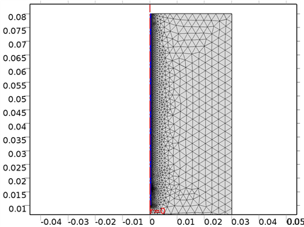
Figure 2. The COMSOL Mesh model within 3 mm.

Figure 3. The COMSOL model for the four point locations to provide the temperature distributions throughout the bone materials.

Table 1. Electrical properties of bone [8] .
5. Simulation Results
The following simulations were conducted at three different frequencies: 900 MHs, 1 GHz, and 2.4 GHz. The temperature distributions obtained for the four different locations in the bones were obtained. The input microwave power was 10:00 Watts, and in one minute simulation time, dissipation was 9.354 Watts. Figure 4 shows the differential temperature distributions for four different frequencies within one minute change. Figure 5 gives the surface power density dissipation at 900 MHz for a one minute simulation. Figure 6 gives the normalized distribution of a damaged tissue. This is given for comparison between homogenous bone materials. Figure 7 demonstrates the temperature distribution for a second type of bone material at 900 MHz. Figure 8 and Figure 9 display the temperature distribution for a damaged tissue at 900 MHz and 1 GHz, respectively. The characteristic difference of the kinds of bones are represented in Figures 10-13.
6. Conclusion
The simulation results show differential power dissipation over the bone materials with different temperatures within 2 - 4 degree change for various frequencies. This simulation also shows the distinction between normal

 (a) (b)
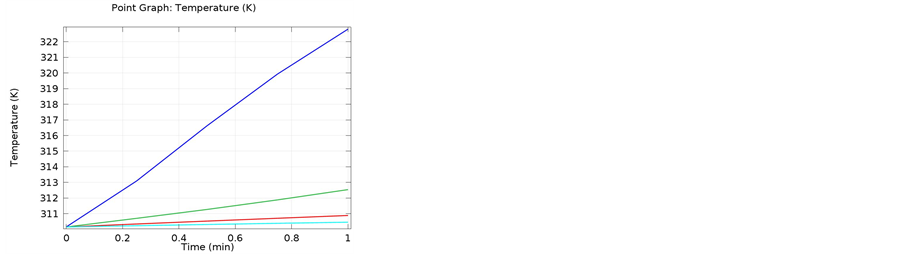
 (c) (d)
Figure 4. The temperature Distributions for various frequencies given for one minute simulation; (a) Data cut for 2D, giving the temperature distribution for the blue curve at 900 MHz, (b) Gives the differential distribution for the four location within the bone materials at 900 MHz, (c) The temperature distribution at the four locations throughout the bone materials at 1 GHz, and (d) The temperature distribution within the bone materials at 2.4 GHz.
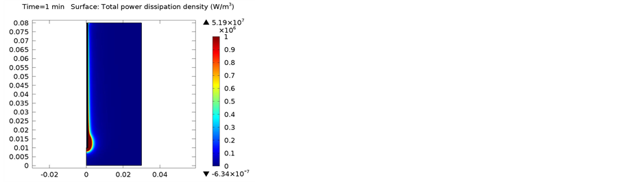
Figure 5. One Minute total power dissipation density (W/m3).

Figure 6. Power distribution for damaged tissue at 900 MHZ.
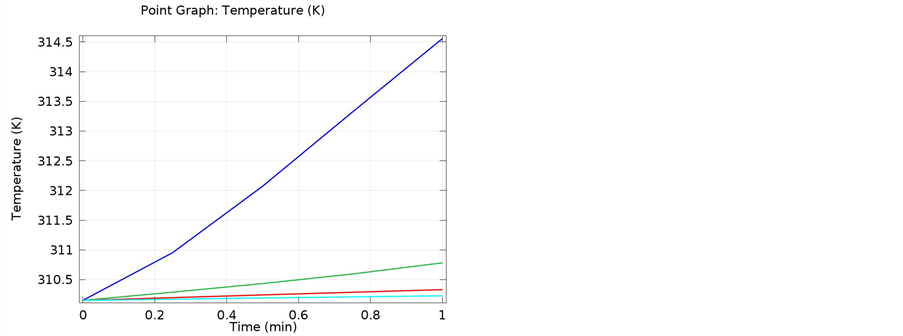
Figure 7. Four point distribution for the bone read throughout the bone materials at 900 MHz, demonstrating temperature distribution throughout the depth of the bone thickness. The curve also shows the thermal energy transmitted for one minute maximum.

Figure 8. Temperature distribution for damaged tissue at 900 MHz. The data shows different distribution for a given bone density, re- presenting a damaged tissue.

Figure 9. Temperature distribution for damaged tissue at 1 GHz. The curve shows the differential distribution as compared to the 900 MHz data.
 (a) (b)
 (c)
(c)
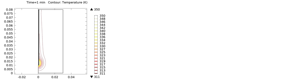
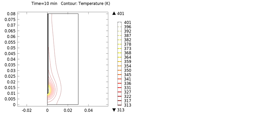
Figure 10. Isothermal contours of red bone marrow at (a) 900 MHz; (b) 1 GHz; (c) 2.4 GHz.

 (a) (b)
 (c)
(c)
Figure 11. Isothermal contours of yellow bone marrow at (a) 900 MHz; (b) 1 GHz; (c) 2.4 GHz.

 (a) (b)
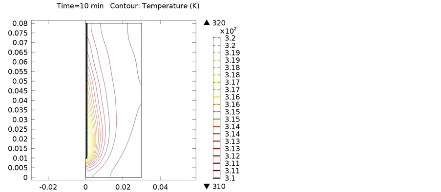 (c)
(c)
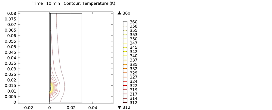
Figure 12. Isothermal contours of cancellous bone at (a) 900 MHz; (b) 1 GHz; (c) 2.4 GHz.

 (a) (b)
 (c)
(c)
Figure 13. Isothermal contours of cortical bone at (a) 900 MHz; (b) 1 GHz; (c) 2.4 GHz.
bone materials and damaged tissues, indicating that this is an effective method for diagnosing bone and tissue pathology. Future consideration will be given to a practical model for a medical setting.
Acknowledgements
The team of authors and Co-Authors acknowledge the INDI facility at IUPUI.
Cite this paper
Vinay KumarSuryadevara,SuyogPatil,JamesRizkalla,AhdyHelmy,PaulSalama,MaherRizkalla, (2016) Microwave/Thermal Analyses for Human Bone Characterization. Journal of Biomedical Science and Engineering,09,101-111. doi: 10.4236/jbise.2016.92006
References
- 1. Krug, R., Burghardt, A.J., Majumdar, S. and Link, T.M. (2010) High-Resolution Imaging Techniques for the Assessment of Osteoporosis. Radiologic Clinics of North America, 48, 601-621.
http://dx.doi.org/10.1016/j.rcl.2010.02.015 - 2. Johnell, O. and Kanis, J. (2005) Epidemiology of Osteoporotic Fractures. Osteoporosis International, 16, S3-S7.
http://dx.doi.org/10.1007/s00198-004-1702-6 - 3. Wong, M.F. and Wiart, J. (2005) Modelling of Electromagnetic Wave Interactions with the Human Body. Comptes Rendus Physique, 6, 585-594.
http://dx.doi.org/10.1016/j.crhy.2005.07.003 - 4. Rouf, H.K., Costen, F. and Fujii, M. (2011) Modeling EM Wave Interactions with Human Body in Frequency Dependent Crank Nicolson Method. Journal of Electromagnetic Waves and Applications, 25, 2429-2441.
http://dx.doi.org/10.1163/156939311798806185 - 5. (ACR), Radiological (2016) Brain Imaging, Functional (Fmri). Radiologyinfo.org. N.p.
- 6. Meaney, P.M., Zhou, T., Goodwin, D., Golnabi, A., Attardo, E.A. and Paulsen, K.D. (2012) Bone Dielectric Property Variation as a Function of Mineralization at Microwave Frequencies. International Journal of Biomedical Imaging, 2012, Article ID: 649612.
- 7. Types of Bones in the Human Body. (n.d.).
http://www.teachpe.com/anatomy/types_of_bones.php - 8. Itis.ethz.ch. (2016) Dielectric Tissue Properties|Average EM Tissue Parameter|Average Thermal Tissue Parameter| Frequency-Dependent Tissue Parameters|Tissue-Specific Parameters|Interactive Tissue Parameter Table IT’ Is Foundation. N.p.
- 9. Safadi, F.F., et al. (2009) Bone Structure, Development and Bone Biology. Bone Pathology, Humana Press, 1-50.