Engineering
Vol.10 No.04(2018), Article ID:83747,5 pages
10.4236/eng.2018.104009
The New Transmission for a Hybrid Car
R. G. Khadeev
State Research and Test Institute of Military Medicine, Moscow, Russia
Copyright © 2018 by author and Scientific Research Publishing Inc.
This work is licensed under the Creative Commons Attribution International License (CC BY 4.0).
http://creativecommons.org/licenses/by/4.0/


Received: February 22, 2018; Accepted: April 10, 2018; Published: April 13, 2018
ABSTRACT
The article deals an innovative device presented in the patent application PCT RU 2017000589, the mechanism for optimization of the work and coordination of the internal combustion engine with transfer of energy to the driving wheels. An original way of incorporating transmission elements through a differential to which the rotational energy is transmitted is proposed. When the engine energy is transmitted, the transmission ratio and torque are automatically adjusted, depending on the load on the output shaft.
Keywords:
Transmission, Asymmetric Differentials, Clutch of Sliding, Torque, Gear Ratio

1. Introduction
The internal combustion engine has a definite dependence on the output power, on the rotational speed of the shaft and has optimal values only in a narrow interval, usually at high revolutions. Compensation for this disadvantage is due to the use of the gearbox. The problem solved by the transmission is the matching of the speed of the wheel to the engine speed to ensure optimal operation of the engine in any mode of motion, from the very start to a full acceleration. At the same time, it is necessary to provide sufficient torque on the wheels of a vehicle. The devices offered for consideration fully solve these problems. They are simple, which means they are reliable and cheap. In addition, they do not require adjustment and control during operation; they are adjusted to the mode automatically. Such a device allows repeatedly expanding the range of optimal operating modes of the engine multiply. This transmission includes planetary asymmetric differential mounted on the drive axis, around which they are able to rotate, having one input and two outputs [1] . Energy flow is divided into two parts. One part with a large torque, and low speed is fed to the output shaft. The second part, through the power clutch of sliding, is connected to the drive shaft and stretches behind it, causing the whole mechanism of the differential to rotate around its axis. If there is no slippage, the entire mechanism then rotates together with the shaft and gear ratio is equal to one. The torque will be equal to the torque of the engine. If slippage in the clutch increases, the output shaft of the differential connected to the clutch is decelerated, the rotation of the differential around its axis then slows down, and the engine energy is more heavily transmitted through the gears of the differential. Gear ratio is increasing; torque on the output shaft is also multiplied. With a gear ratio of the elements of the differential to fifteen, the efficiency is not less than 0.95. The torque is also increased by a factor of fifteen. When the load on the shaft changes, the transmission ratio and torque automatically change.
2. Operation of the Device
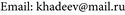
The scheme of the transmission is shown in the Figure 1. The input of the differential―the planetary carrier 7 is connected to the motor shaft 1. A rotor of the
Figure 1. The scheme of the transmission. 1. Motor shaft; 2. Rotor of the generator; 3. Central gear; 4. Stator of the generator; 5. Friction clutch; 6. 8. Satellites; 7. The carrier of the planetary gear; 9. Central gear; 10. Output shaft of the first differential; 11. Disc of the friction clutch; 12. Friction clutch disk connected to the second differential output; 13. Crown; 14. Satellites; 15. Central gear; 16. The carrier of the planetary gear; 17. Output shaft; 18. Synchronizer assembly; 19. Electromotor; 20. Electromotor shaft; 21. The carrier of the planetary gear; 22. Satellites; 23. Inductor of electromagnetic clutch; 24. Central gear; 25. Anchor of electromagnetic clutch; 26. Output shaft of the electromotor; 27. Crown.
generator 2 also connected to its input 1. One output is connected to the output shaft of the first differential 10, and the second output, through the central gear 3 is connected to the stator of the generator 4 and the stator is able to rotate about the output shaft of the first differential 10, and the second output, through the central gear 3 is connected to the stator of the generator 4 and the stator is able to rotate about the axis. The stator together with the rotor forms an electric machine of double rotation. The second output of the first differential is also connected to the controllable friction clutch 5. The response part of this clutch is connected to the transmission housing. The friction clutch 5, has the ability to lock the second output and the stator of the generator, connecting it to the housing. Rotation from the motor is transmitted to the rotor of the generator 2 and to the carrier of the differential 7, then through its elements 8, 9 to the driven shaft 10 which rotates in the same direction as the motor shaft rotates and to the second output of the differential 3, is connected to the stator of the generator 4, which tends to rotate to the side, reverse to the direction of rotation of the generator rotor. If there is an electrical load in the generator circuit between the stator and the rotor, as a result of mutual induction, a force arises that entrains the stator behind the rotor, partially blocking the differential. This causes it to accelerate its rotation around its axis, which leads to a reduction in the transmission ratio consisting of the transfer of motion through the differential elements and rotation around the axis, which increases the speed of rotation of the driven shaft. If necessary, the second output of the differential is locked by a coupling, connecting it to the housing, transforming the differential into a reducer. The stator of the generator stops. Since the generator is a reversible electric machine it can be used to start the engine, as well as to increase the acceleration rate of a vehicle at start-up and in other cases, as well as for driving on electric traction.
3. Operation of the Coupling Mechanism
The second differential is a coupling mechanism, which, moreover, can increase the output torque during acceleration. This makes it possible to greatly simplify transmission. For example, during acceleration, when the clutch slips, the torque can be increased several times, and the first gear will not be required [2] . Input of the differential and its two outlets are also concentrically arranged on one axis. One output of the second differential is connected to the crown 13 and to the driven shaft 17. The second output―the central gear 15, is connected to a disk of the controllable slip clutch 12. The response disk 11 of which is connected to the input of the differential. The coupling does not connect the drive shaft and slave directly, but only controls the operation of the differential. When the clutch does not slip, the differential is completely blocked, the gear ratio is equal to one, torque at the output is equal to the torque at its input. When the clutch slips, more energy is transferred from the carrier 16 through gears 14 to the crown 13, connected to the output shaft. Gear ratio and torque on the output shaft are increased. Such a clutch mechanism can be installed into a conventional, not only in a hybrid, car. It will provide a multiple increase in torque on a wheel during the start and acceleration, as well as smoothness (softness) in the operation of the clutch mechanism.
4. Connection of the Electric Motors
Electric current produced by the generator when controlling operation of the first differential mechanism is supplied to consumers, for example, to electric motors connected to wheels not connected to the driven shaft of the transmission. They are connected via a device consisting of an asymmetrical planetary differential gear and an electromagnetic clutch of the slip connected to it. The mechanism can be located in the motor housing, in its own housing, or inside a wheel. The motor shaft 20 is connected to input of the differential with its planetary carrier 21 and the anchor of electromagnetic clutch 25. One output of the differential is connected to the crown 27 connected to the output shaft 26 and the second is connected to inductor 23. The second output of the differential tends to rotate in the opposite direction with respect to direction of rotation of the motor and the first output of the differential, but bringing up electromagnetic induction force between armatures and inductor. The armature pulls the inductor and the second output of the differential with the central wheel 24, partially blocks the differential and reduces overall transmission ratio, contributing to the acceleration of the driven shaft. With increasing load on the driven shaft, the mutual sliding of the rotor and the inductor increases, and the rotation is mostly transmitted through the gears of the differential, its rotation around the axis slows down, the transmission ratio to the driven shaft increases. Shaft rotation decreases, and torque increases. With a constant torque and the rotor speed of the electric motor, the turnovers of the driven shaft and the torque automatically on vary within wide limits, depending on the required torque value. Their values are determined by the parameters of the differential. At start of a vehicle, the gear ratio from the electric motor to the driven wheel is maximal. The torque is also maximal and equals multiple times the engine torque.
5. Conclusions
This Method for Automatically Converting of Gear Ratio and of Torque is described in the author’s article [3] and discussed in [4] . All three main elements of the transmission always work in the automatic adjustment mode and in the optimal mode. This connection of the generator and the motor allows the use of a wide range of the changes in attitudes and torque on the output. The clutch mechanism does not transfer the entire torque through the friction clutch discs, but only part of it. The load to the clutch is less than in a conventional design. Electric motors operate in the optimal mode from the very beginning of the movement. All three main elements of the transmission always work in the automatic adjustment mode and in the optimal mode. The important quality of such a transmission is its simplicity. The fabricated and investigated models of such a transmission showed its reliability and optimal operation in all modes.
The transmission elements demonstrate the declared qualities. Figure 2 shows

Figure 2. Machine model. 1. Motor; 2. Generator; 3. Clutch.
one of the models, used to test the properties of the mechanism. Here, the motor is connected to the generator so that the transmission ratio is to be equal to sixteen. In the clutch, the torque is doubled.
Cite this paper
Khadeev, R.G. (2018) The New Transmission for a Hybrid Car. Engineering, 10, 125-129. https://doi.org/10.4236/eng.2018.104009
References
- 1. Khadeev, R.G. (2014) Hybrid Drives. Vestnik Mashinostroeniya, 1, 87-88.
- 2. Khadeev, R.G. (2012) Coupling with an Asymmetric Differential. Russian Engineering Research, 6, 723-724. https://doi.org/10.3103/S1068798X1206010X
- 3. Khadeev, R.G. (2016)) A Method for Automatically Converting of Gear Ratio and of Torque. The Required International Conference on Design and Production Engineering, Berlin, 25-26 July 2016, 83.
- 4. Khadeev, R.G. (2015) A Simple Way to Control the Torque and Turns the Electric Motor. International Journal of Emerging Engineering Research and Technology, 10, 1-3.