Engineering
Vol. 4 No. 12 (2012) , Article ID: 25739 , 4 pages DOI:10.4236/eng.2012.412106
Design Considerations for Pile Groups Supporting Marine Structures with Respect to Scour
Department of Irrigation and Hydraulics, Faculty of Engineering, Ain Shams University, Cairo, Egypt
Email: yasser_mostafa@eng.asu.edu.eg
Received October 12, 2012; revised November 13, 2012; accepted November 23, 2012
Keywords: Piles; Pile Groups; Marine Structures; Scour; Battered Piles
ABSTRACT
Piles supporting marine structures such as jetties, relieving platforms, quay walls and fixed offshore structures are subjected to lateral loads due to berthing and mooring forces, wind, waves, storm surges and current forces. This paper presents some factors that affect the design of pile groups supporting marine structures founded in cohesionless soils. Some main aspects that should be considered in the pile group design are addressed such as pile batter angle, pile group arrangement, pile spacing, pile slenderness ratio and magnitude of lateral static loading. Numerical analyses were conducted to investigate these design aspects with and without impact of scour. Different scour depths were considered to cover the possible root causes of scour around pile groups such as waves, current and ship propeller jets. The study revealed that scour has greater impact on lateral loading of pile groups compared to its impact on single piles. Pile groups with side-by-side arrangement exposed to scour are more critical than single piles and piles groups with tandem arrangement due to the combined effect of scour and pile-soil-pile interaction. It is also concluded that scour protection is not always required. More attention and considerations should be given to scour protection around piles especially if the piles are closely spaced, arranged side-by-side and if slenderness ratio is less than 12.5.
1. Introduction
Marine structures such as jetties, seawalls, relieving platforms, quay walls and fixed offshore (jacket type) structures are often supported on pile groups. The foundation piles usually comprise a large portion of the marine structure cost. These piles are usually subjected to large lateral loads induced from waves, currents, vessel berthing and mooring forces. Also, these piles are subjected to scour due to waves, current and ship propeller jets.
Marine structures and bridge piers supported on pile groups can fail due to severe scour. Numerous publications are found in the literature for investigating the scour around piles for bridge piers and a smaller number of publications investigating the scour around marine structures. Moreover, a very limited number of publications regarding the effect of scour on the behavior of pile groups is found in the literature. Vertical pile capacity is composed of friction along pile length and end bearing at pile toe while pile lateral capacity highly depends on the soil conditions surrounding the top one third of pile length. Therefore, scour impact on lateral pile capacity is more significant than the scour impact on vertical pile capacity.
Global scour refers to a general lowering of the ground surface over a wide area. Figure 1 shows global scour around a fixed offshore structure supported on piles.
Scour around piles varies due to the root cause. For single piles, scour depth in sandy soils (ds) is 1.3 times pile diameter (d) with a mean of 0.7 [1]. In another meaning, the ultimate scour depth is about 2 times the pile diameter (i.e., ds/d = 2). However, this value can be different for scour due to waves only or due to ship propeller jets only. Some research has been performed to examine the scour around pile groups due to waves and currents such as Sumer and Fredsøe [2], Mostafa and Agamy [3]. However, very limited research has examined how to eva-
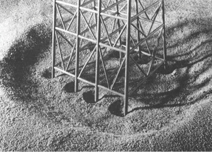
Figure 1. Global scour: wide depression around a jacket structure (after Whitehouse [10]).
luate the effects of scour on the behavior of pile groups. Among this limited research, recent research focused on piles supporting bridge piers such as Lin et al. [4].
Effect of scour on lateral loading of single piles has been investigated in a few recent publications such as Kishore et al. [5], Lin et al. [6], Mostafa [7] and Ni et al. [8]. Mostafa [7] reported that scour has significant impact on single piles installed in sand and less significant impact on piles installed in clay. Also, Mostafa [7] reported that ultimate lateral capacity for single pile subjected to global scour is found to be about 50% to 70% of ultimate lateral capacity of pile subjected to local scour depending on the scour hole dimension.
As piles are usually installed in groups, it becomes necessary to study the effect of scour on the behavior of pile group not just single piles. The combination of scour and pile-soil-pile interaction (i.e., group effect) can lead to a significant reduction in lateral pile capacity and consequently may lead to the failure of marine structures.
This paper presents the impact of global scour around batter and vertical pile groups installed in medium dense sand. The software program GROUP V.7.0 [9] was used in the analyses. For calibration, results from the software were compared with experimental tests on batter pile groups found in the literature.
Different design parameters were investigated in this paper such as pile batter angle, pile group arrangement, pile spacing and pile slenderness ratio. The impact of scour depth on all these parameters was investigated. Only global scour was considered in this study as it has more significant impacts compared to local scour.
Based on the results of the numerical analyses, this paper also provides general recommendations and guidelines on the necessity of using scour protection. Scour protection using riprap or geotextile may be necessary sometimes and may be a waste of money in other cases. The decision to protect the piles from scour depends on the maximum anticipated scour depth based on the root cause of scour and also depends on the pile, soil and loading conditions.
2. Numerical Analysis and Validation with Previous Experiments
In this paper, numerical analyses were conducted to investigate several parameters affecting the design of pile groups supporting marine structures subjected to scour. The software program Group [9] was used in the analysis. GROUP is a 3D software program for analyzing pile groups subjected to axial and lateral loads. A solution requires iteration to accommodate the nonlinear response of each pile in the group model. The program GROUP solves the nonlinear response of each pile under combined loadings. For closely-spaced piles, the pile-soilpile interaction is taken into account by introducing reduction factors for the p-y curves used for each single pile. These reduction factors or called “p-multipliers” are generated based on results of laboratory and field experiments published in the literature.
A comparison between the results from the computer program Group [9], results from the program Piglet [11] and experimental tests of batter pile groups performed by Zhang et al. [12] was conducted. Batter piles are widely used to support marine structures especially for structures subjected to relatively large lateral loads. Zhang et al. [12] carried out 18 different lateral load tests in the centrifuge on 3 × 3 and 4 × 4 fixed head battered pile groups to investigate the effects of vertical load on the group lateral resistance in cohesionless soils. Zhang et al. [12] proved that designs based on standard lateral load tests with small vertical dead loads would be on the safe side.
Figure 2 shows a sketch of the prototype 3 × 3 battered pile group simulated by the centrifuge models. Two pile arrangements were simulated for the 3 × 3 pile group (Zhang et al. [12]). In the first arrangement, the side pile rows were battered forward at 1:8 slope and the middle row was battered reverse at 1:4 slope (referred to as the 6F3R arrangement). In the second arrangement, the side pile rows were battered reverse at 1:8 slope and the middle row was battered at 1:4 slope (3F6R arrangement). The piles were square aluminum with 304 mm in length and 9.5 mm in width. In prototype scales, the width, total length and embedded length of the piles were 0.43, 13.7 and 10.4 m, respectively and the free length from the ground surface to the point of lateral load application was 2.7 m. The piles were three-diameter spaced and rigidly attached to the pile cap. The soil comprised medium dense sand with relative density (Dr) of 55%.
Figure 3(a) shows the load-deflection curve for the 3 × 3 battered piles with 3F6R arrangement. Results from the computer programs Group and Piglet provide reasonable estimate in comparison with the centrifuge experiments. For low lateral loads, the computer programs tends to slightly overestimate the lateral deflection com-
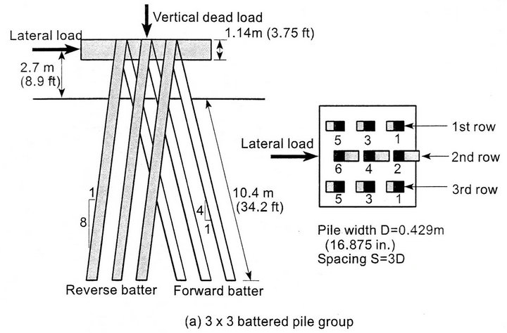
Figure 2. Prototype 3 × 3 battered pile groups tests (after Zhang et al. [12]).
 (a)
(a)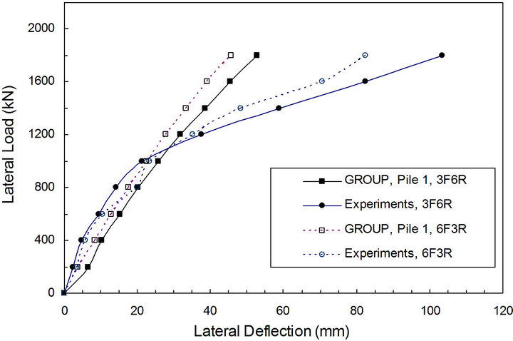 (b)
(b)
Figure 3. Load-deflection curves for the 3 × 3 battered pile groups considering two pile arrangements: (a) 3F6R arrangement and (b) 6F3R arrangement.
pared to experimental results; while for the large lateral loads, the computer programs tend to underestimate the lateral deflections. Figure 3(b) indicates that, for the same lateral load, pile group with 6F3R arrangement has less deflection than that for the 3F6R arrangement. This can be attributed to the fact that in the case of 6F3R arrangement six piles have steeper batter angle slope (1:4) and three piles have milder batter angle slope (1:8) which provides higher lateral resistance than the case of 3F6R arrangement.
3. Effect of Batter Angle
Batter (raked) piles are widely used to support marine structures as they are effective in restricting horizontal displacement of the foundation subjected to large lateral loads or in a liquefied soil flow environment. The disadvantages of such piles are the larger axial forces in the piles [13]. The forces on piles supporting coastal structures are axial vertical loads due to own weight, loads from trucks and cranes and lateral loads from ship impacts, wave loads and mooring forces. The use of batter piles along with vertical piles increases the overall pile group efficiency. As reported by Rajashree and Sitharam [14], Batter piles are classified as positive batter (slip surface deflects upward) and negative batter (slip surface deflects downward) depending on the formation of slip surfaces [15]. Figure 4 illustrates the negative and positive batter piles.
In this paper, the effect of batter angle was investigated. In the analysis, all piles were assumed to be steel piles with outside diameter (d) of 0.5 m, total pile length (L) of 30 m and cross section area (A) of 0.01944 m2. The pile spacing to diameter ratio (S/d) was taken to be 3. The distance between point of lateral load at the jetty deck and the seabed (i.e., pile free length, Lf) was assumed to be 5 m. This free length is required for vessels berthing and it varies depending on the vessel draft, under keel clearance and distance between sea level and jetty deck level. All pile heads were assumed to be fixed to the jetty deck. The soil was assumed to be medium dense sand with a unit weight (g) of 17 kN/m3 and angle of internal friction (f) of 35˚. The ratio between pile and soil modulus of elasticity (Ep/Es) was assumed to be 2000. In the analysis, two piles were considered; one pile has negative batter and the other one has positive batter. Different batter angles of 0˚, 5˚, 10˚ and 20˚ were investigated.
Load-displacement curves for different pile batter angles are shown in Figure 5. For the same lateral loading on pile group, a small batter angle significantly reduces the lateral pile displacement. For example, for a lateral load of 400 kN applied to the group at the deck level, the normalized lateral pile displacement (y/d) is 0.23 for vertical piles (b = 0˚) and about 0.1 for batter piles with angle b of 5˚ (i.e., reduction of 57% in pile head displacement). It is also noted that increasing the batter angle from b = 0˚ to b = 5˚ increases the lateral capacity from 400 kN to 700 kN (i.e., increase of 75% of lateral capacity).
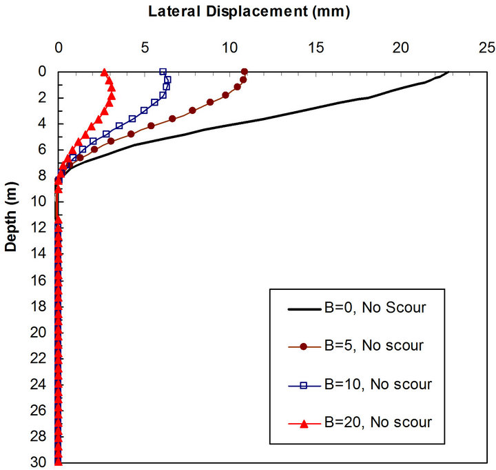
Figure 6 shows the lateral displacement and bending moment along pile length if the pile group is subjected to lateral load of 100 kN applied at the pile cap. A slight increase in the batter angle significantly reduces the lateral pile displacement and bending moment. It is worth
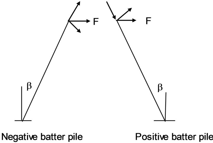
Figure 4. Sketch of negative and positive batter piles.
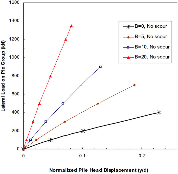
Figure 5. Load-displacement curves for different pile batter angle.
 (a)
(a)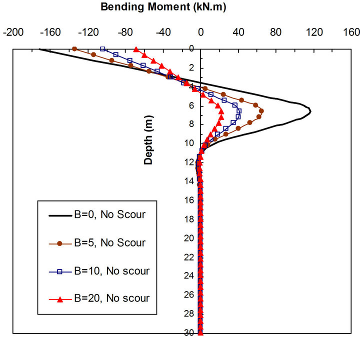 (b)
(b)
Figure 6. Effect of batter angle on the pile response (F = 100 kN) (a) Shear force along pile length; (b) Bending moment along pile length.
mentioning that bending moment and deflection of positive batter piles are almost similar or slightly higher than that for negative batter piles. This may be attributed to the pile head conditions which were assumed to be fixed in all analyses. Due to scale limitations, only negative piles are presented.
Figure 7 shows that lateral pile group capacity significantly increases by the increase in batter angle. A batter angle of 5˚ increases the lateral capacity by about 40% over vertical piles (b = 0). The increase in the group capacity is almost linear. The rate of increase in capacity if b ranges between 10˚ and 20˚ is higher than that rate if b ranges between 0˚ and 10˚. If scour depth equivalent to twice pile diameter (ds/d = 2) is considered, the group lateral capacity decreases by about 5% to 10%. The rate of change decreases with the increase in batter angle. In another meaning, the scour becomes less significant with the increase in batter angle.
Wave loading is cyclic in nature. In offshore conditions the number of cycles of wave loading may be up to 600 [14]. The cyclic loading causes a gap between the pile and soil interface. Effect of cyclic loading on the behavior of pile groups was examined in this paper. No major difference was found in the results for the cyclic loading conditions compared to static loading conditions. This is because the analysis was performed in sandy soils as sand tends to fill the gap between the pile and soil interface during cyclic loading. For cohesive soils, cyclic loading is expected to have larger impact on the piles compared to static loading.
Caution should be exercised for seismic loading conditions as it has been reported in some publications that batter piles have poor performance during recent earthquakes [16].
4. Effect of Scour on Vertical Pile Groups
Effect of global scour on vertical pile groups was investtigated. Several parameters were considered including the variation in scour depth. The effect of scour depth

Figure 7. Relationship between pile batter angle and the lateral pile group capacity (d = 0.5 m, L = 30 m, Lf = 5 m, S/d = 3).
combined with other parameters such as different pile arrangement, spacing between piles and pile slenderness ratio were investigated.
The same soil and pile characteristics described in Section 3 were assumed except that all piles are considered to be vertical. All pile groups comprised two piles. No free length was assumed in the analysis of vertical piles.
Assuming the piles are Grade 4 steel with a yield stress of 450 MPa, the equivalent moment causing the pile to yield is about 1040 kN/m. The ultimate lateral pile capacity corresponds to the load that causes the yield moment.
4.1. Scour Depth around Pile Groups
The scour depth around pile groups is based on the root cause of scour. Piles supporting coastal and marine structures are subjected to scour due to waves, currents and ship propeller jets. A summary of the expected scour depth due to these causes is provided in the following subsections.
4.1.1. Scour Due to Waves and Current
Some experimental research has been performed to examine the scour around pile groups due to waves and currents. Sumer and Fredsøe [2] examined the wave scour around a group of closed spaced piles. Sumer et al. [17] investigated the global and local scour at pile groups exposed to steady currents. Mostafa and Agamy [3] examined the combined effect of waves and current on a group of closed and widely spaced piles. Scour depth to pile diameter ratio (ds/d) due to waves only can be as high as 1 for Keulegan-Carpenter number (KC) of 13. For pile groups exposed to currents only, total scour (global scour and local scour) increases with the increase in number of piles. The scour depth to pile diameter ratio (ds/d) can be as high as 2.6 [17].
4.1.2 Scour Due to Ship Propeller Jets
During berthing or de-berthing operations, a ship is in proximity to harbor structures and erosion may occur around piles supporting jetties or relieving platforms and sloping riprap [18]. Figure 8 shows a sketch of scour around piles supporting jetties or relieving platforms due to ship propeller jets. It is noticed that scour at the front (leading) pile is larger than that at the trailing (aft) pile. If pile spacing increases, scour at the trailing pile decreases as a result of the deposition of scoured sediment taking place at the vicinity of the front pile as can be seen in Figure 8.
Yuksel et al. [18] concluded that maximum scour depth and sand deposition for pile groups vary significantly with densimetric Froude number Frd, pile spacing to diameter ratio (S/d) and pile diameter to jet diameter ratio (d/do). Scour at the front (leading) pile is larger than that at the trailing (aft) pile. Empirical equations for scour calculations due to ship propeller jets can be found in the literature. Experimental results of Yuksel et al. [18] indicated that maximum scour depth to pile diameter ratio (ds/d) is about 2.25.
In this paper, normalized scour depth (ds/d) between 0 and 3 was considered in the analysis to cover the different root causes of scour around piles supporting coastal structures.
4.2. Effect of Pile Arrangement
The analysis considered two main pile groups. The pile groups were assumed to be arranged side-by-side (i.e., q = 90˚) or tandem arrangement (i.e., q = 0˚) where q is the angle between the lateral load and the line connecting the two piles and S is the centre line to centre line spacing between piles. Figure 9 shows a general sketch indicating a pile location within a pile group subjected to lateral loading. The piles were assumed to be spaced three times the pile diameter (i.e., S/d = 3). Pile-soil-pile interaction was considered in the analysis. The reduction factors generated in the program Group [9] were used in this study. The length to diameter ratio (L/d) was assumed to be 60 so that pile embedment length has no impact on the results.
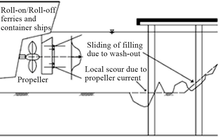
Figure 8. Erosion of seabed due to ship propeller jets (Chin et al., 1996 [19]).

Figure 9. The location of a pile in pile group under lateral loading.
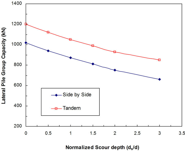
Figure 10 shows the effect of normalized scour depth (ds/d) on the lateral capacity of a group of two piles with side-by-side arrangement and tandem arrangement. Figure 10(b) indicates that the reduction in pile group capacity of groups with side-by-side arrangement is higher than that for groups with tandem arrangement. A relatively small scour depth (ds/d = 1) leads to a reduction in lateral group capacity ranging between about 12.5% and 15% for piles with tandem arrangement and side-by-side arrangement, respectively. A scour depth of three pile diameter (i.e., ds/d = 3) causes a reduction in the lateral group capacity ranging between 29% and 35% for piles with tandem arrangement and side-by-side arrangement, respectively. The rate of reduction in lateral group capacity if ds/d varies between 0 and 1 is slightly higher than that if ds/d is between 1 and 3.
Figure 11 shows load-displacement curves for groups of two piles with tandem arrangement (q = 0˚) and sideby-side arrangement (q = 90˚) neglecting and considering scour. Load-displacement curves for single pile computed using program LPILE were plotted for comparison. It can be seen that the load-displacement curve for single
 (a)
(a)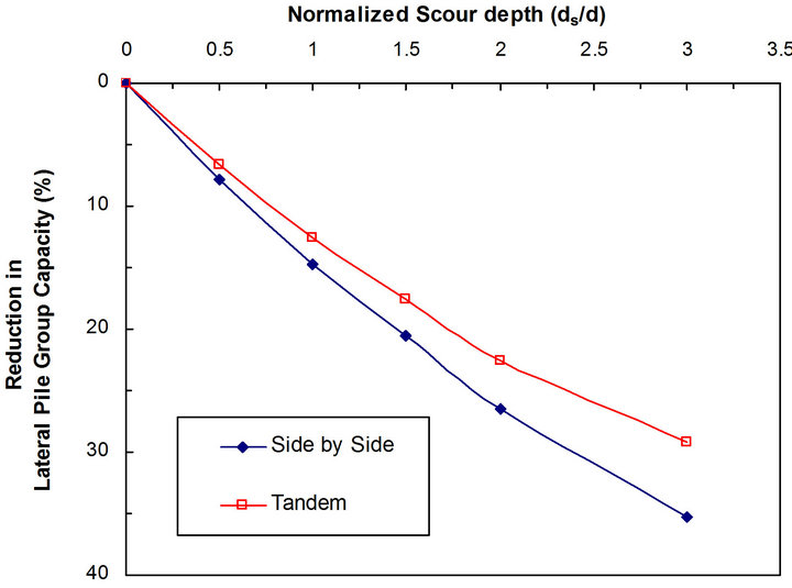 (b)
(b)
Figure 10. Relationship between normalized scour depth and lateral pile capacity (S/d = 3, L = 30 m, L/d = 60).
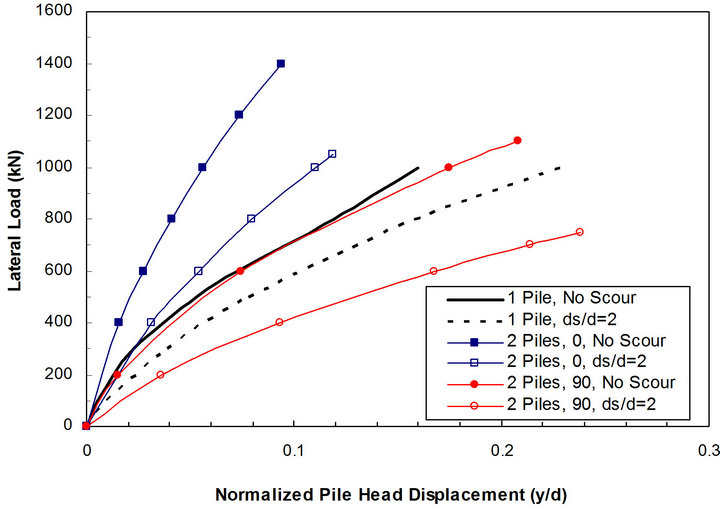
Figure 11. Load-displacement curves for single pile and pile groups with different arrangement neglecting and considering scour (S/d = 3, L = 30 m, L/d = 60).
pile is very similar to that for two piles with side-by-side arrangement. This is because the side-by-side reduction factor due to group interaction is negligible if the spacing is greater than three times the pile diameter [Group] [9]. For the same lateral loading, pile group with tandem arrangement has less displacement than that for pile group with side-by-side arrangement. For relatively small lateral loads on the group (F < 100 kN) no major differences in the normalized pile head displacement (y/d) are found due to pile group arrangement. The impact of pile arrangement is more pronounced with the increase in lateral loading due to the nonlinearity in the pile-soil system. For single pile and pile groups with different arrangements, scour increases the pile head displacement. For the same lateral loading, piles with tandem arrangement even when scour is considered has lower displacement than the piles with side-by-side arrangement with no scour. This is due to the greater reduction in group efficiency for side-by-side arrangement compared to the reduction in group efficiency for tandem arrangement.
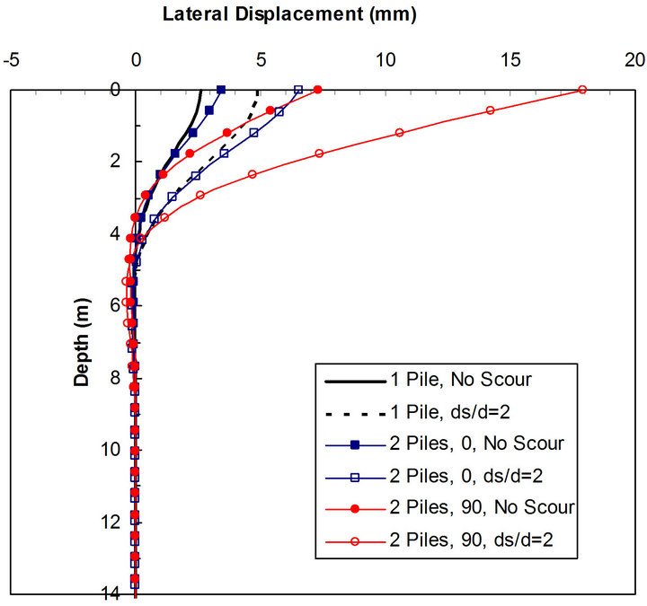
Figure 12 shows lateral displacement and bending moment along pile length when a group of two piles is subjected to lateral load (F) of 200 kN. For the sake of comparison, single pile subjected to lateral load of 100 kN was computed and plotted. It is noted that displacement of piles with side-by-side arrangement (q = 90˚) is higher than that for single pile and pile group with tandem arrangement (q = 0˚). Scour depth of twice pile diameter increases the head displacement of pile group with side-by-side arrangement from 7.4 mm to 18 mm (i.e., increase by about 114%). For piles with tandem arrangement, the displacement at pile head increases due to scour from about 3.4 mm to 6.5 mm (i.e., increase by about 91%). For the single pile, scour increased the pile head displacement from about 2.6 mm to about 4.9 mm (i.e., increase by about 88%). Under the same loading conditions, the displacement of pile group is higher than that for single pile. This is attributed to the pile-soil-pile
 (a)
(a)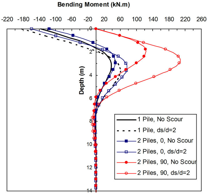 (b)
(b)
Figure 12. Effect of pile arrangement on lateral response along pile length, (a) Lateral displacement; (b) Bending moment (F = 200 kN, S/d = 3, L = 30 m, L/d = 60).
interaction. The scour effect on pile group with side-byside arrangement is more significant than that for single piles and pile group with tandem arrangement. The bending moment for piles with side-by-side arrangement is larger than that for single pile and pile group with tandem arrangement.
4.3. Effect of Pile Spacing
The effect of centre line to centre line pile spacing considering pile-soil-pile interaction was evaluated. Spacing to diameter ratio (S/d) of 1, 3 and 5 for pile groups with tandem and side-by-side arrangements was considered. The impact of scour is also investigated.
When piles are closely spaced, the shear failure planes resulting from the movement of each pile will overlap and the ultimate resistance for a pile in a group may be less than that of a single pile. This is called “shadow effect” or “pile-soil-pile interaction” which influences the efficiency of individual piles in a group. Reduction factors generated in the program Group [9] were used in this study. These reduction factors are based on many laboratory and field experiments collected from the literature.
Brown et al. [20] introduced the concept of the pmultiplier. This concept represents the response of the group to lateral loading in terms of the response of an assembly of single piles with the soil reaction modeled using p-y curves adjusted using a “p-multiplier” where p is the lateral soil reaction and y is lateral pile displacement. The p-multiplier assumes a different value that depends on whether a pile is in a leading or in a trailing position and the angle between the line connecting two piles and the load direction.
Figure 13 shows the relationship between normalized scour depth and lateral pile group capacity taking into consideration the reduction in group efficiency due to pile-soil-pile interaction. It is evident that the lateral pile group capacity for the two piles with tandem arrangement is higher than that of the two piles with side-by-side arrangement by about 18% to 32%. For closely spaced piles (i.e., S/d = 1) the group capacity is reduced by about 11% and 5% for case of side-by-side arrangement and tandem arrangement respectively. A scour depth equivalent to three times pile diameter decreases the lateral group capacity by about 32% to 35% for groups with side-by side arrangement. The same scour depth reduced the capacity by about 27% to 30% for groups with tandem arrangement.
It should be noted that for tandem arrangement, the ultimate lateral capacity of trailing pile is lower than that of leading pile assuming the scour depth is the same at leading and trailing piles. Therefore, lateral load that causes yield moment of trailing pile was considered in Figure 13.
Figure 14 shows load-displacement curves for two pile group with side-by-side arrangement considering dif-
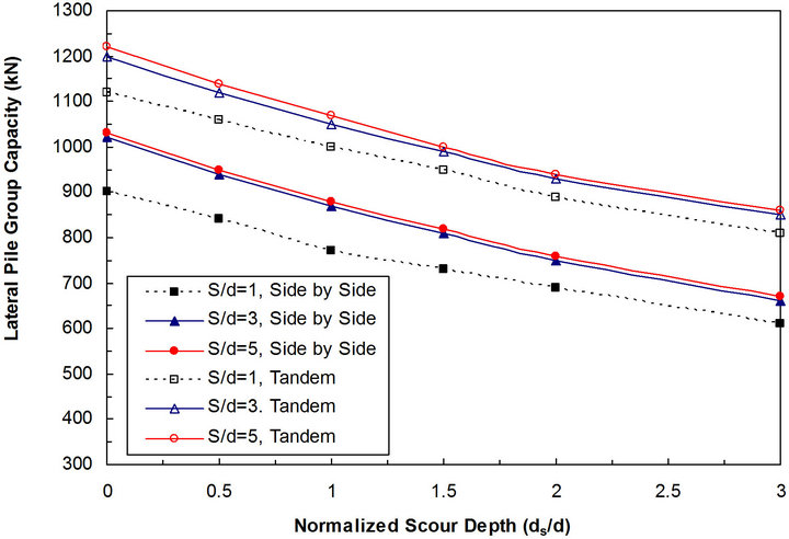
Figure 13. Normalized scour depth versus lateral pile group capacity for different pile spacing and arrangement.
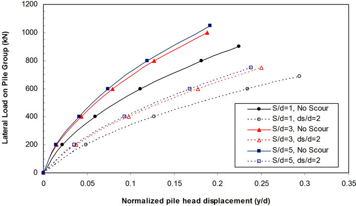
Figure 14. Load-displacement curves for pile group with different pile spacing with and without scour (side-by-side arrangement, L/d = 60).
ferent pile spacings. Impact of scour was also considered by assuming a scour depth equivalent to twice the pile diameter. Figure 14 indicates that pile displacement increases significantly when the piles are closely spaced and scour is considered. As expected, the ultimate group capacity increases with the increase in pile spacing and if scour is neglected. The effect of scour is more pronounced with the increase in lateral loading. As an example, a lateral load of 600 kN on a group with S/d = 1 causes a displacement (y/d) of 0.11 and 0.23 if scour is neglected and considered, respectively. For the same lateral load applied on a group of widely spaced piles (S/d = 5), y/d is computed to be 0.074 and 0.17 if scour is neglected and considered, respectively. For the same pile spacing ratio, the displacement increases by about 100% to 130% due to scour. If scour is neglected and pile spacing ratio is varied, the displacement increases by about 7% if S/d is reduced from 5 to 3 and the displacement increases by about 40% if S/d is reduced from 3 to 1. This is due to the pile-soil-pile interaction. If scour is neglected, the ultimate lateral group capacity is reduced from 1050 kN if S/d = 5 to 900 kN if S/d = 1. This corresponds to a reduction of about 14% due to pile-soil-pile interaction. For the same S/d ratio, the ultimate lateral capacity reduces by about 23% to 29% due to the scour effect.
Therefore, it is concluded that the effect of scour on lateral group capacity and displacement is more pronounced than the effect of pile-soil-pile interaction.
4.4. Effect of Pile Slenderness Ratio
Pile length to diameter ratio (slenderness ratio) may be critical for piles supporting coastal structures under scoured conditions. To examine the effect of pile slenderness ratio, L/d ratios of 5, 7.5, 10, 12.5, 15, 20 and 40 were considered. Pile slenderness ratio for some dolphins or suction piles may be as low as 5. The pile spacing ratio (S/d) was kept constant as 3. Groups of two piles with side-by-side arrangement were considered as this is a more critical case than groups with tandem arrangement.
Figure 15 shows the relationship between normalized scour depth and lateral pile capacity for different pile slenderness ratio. It is noted that for L/d = 5, the rate of decrease in lateral pile group capacity between ds/d = 0 to 0.5 is higher than that rate if ds/d varies between 0.5 and 3. For L/d = 7.5 and 10, the rate of decrease in lateral group capacity between ds/d = 0 and 1 is higher than that rate if ds/d varies between 1 to 3.
It is also noted from Figure 15 that percentage decrease in lateral pile group capacity (PDC) remains almost constant after the pile slenderness ratio is greater than about 12.5. In another meaning, for pile groups exposed to scour, increasing L/d ratio over 12.5 will not add much difference to the group capacity. Accordingly, the decrease in group capacity due to scouring will be more serious for short piles. This is somewhat similar to a conclusion drawn by Ni et al. [8] who concluded that for single piles, PDC values remain almost constant after L/d is greater than 10.
5. Scour Protection
As discussed in this paper, pile groups subjected to scour due to waves, current and ship propeller jets may be exposed to a scour depth up to 2.6 pile diameter. A value of scour depth to diameter ratio (ds/d) of 2 is often used in practice. It is important for designers and practitioners to know when scour protection around piles supporting coastal structures may be necessary and when it is not.
According to Mostafa and Agamy [3] and Abdeldayem et al. [21], pile groups with side-by-side arrangement causes more scour than groups with tandem arrangement. Scour depth for some cases of pile groups with side-by-side arrangement increases as much as about two times more than its magnitude for the case of single pile according to Mostafa and Agamy [3] and Sumer et al. [17]. Accordingly, for a jetty or berthing structure supported on piles exposed to scour due to ship propeller jets, the
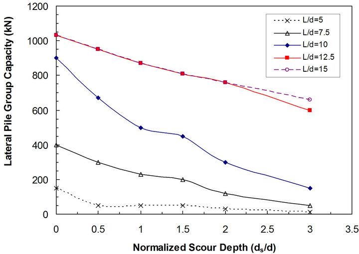
Figure 15. Lateral pile group capacity versus normalized scour depth (ds/d) considering different pile slenderness ratio (L/d) (S/d = 3, side-by-side arrangement).
leading pile row, which is arranged side-by-side, is expected to suffer more from scour.
From a geotechnical prospective, the ultimate lateral capacity for piles arranged side-by-side is lower than that for piles with tandem arrangement. The side-by-side arrangement is exposed to higher lateral deflections and bending moments. Therefore, the combined effect of scour and pile-soil-pile interaction for closely spaced piles makes the side-by-side arrangement the worst case scenario in terms of significant reduction in pile capacity. This scenario may be even worse if the loading arm or free length (distance between jetty deck level and seabed) is high. In this case, scour protection and frequent monitoring of erosion around the piles may be required.
For raked piles, as scour is less significant when the batter pile angle increases, scour protection is not necessary depending on the required lateral pile capacity.
For short piles, consideration should be given to using scour protection measures such as riprap or geotextile. Alternatively, consideration should be given to increasing the pile length so that the slenderness ratio is about 12.5. For already constructed piles with slenderness ratio less than 12.5, consideration should be given to using a suitable scour protection measure.
It should be noted that this section provides general recommendations on when to use scour protection. The decision to use scour protection around piles should be taken based on the pile, soil and loading conditions.
6. Conclusions
Some design aspects of pile groups supporting marine structures founded on cohesionless soils were studied using numerical modeling. These aspects are scour depth, lateral static loading, batter pile angle, pile group arrangement, pile spacing and pile slenderness ratio. For the input data assumed in the analyses, the following conclusions can be drawn:
1) A small increase in batter pile angle increases the lateral pile capacity significantly. A batter angle of 5˚ increases the lateral capacity by about 40% over vertical piles.
2) Scour depth becomes less significant with the increase in pile batter angle.
3) Pile groups with side-by-side arrangement experience higher displacement and bending moments compared to single piles and pile groups with tandem arrangement due to the combined effect of scour depth and pilesoil-pile interaction.
4) The ultimate lateral capacity for pile groups with side-by-side arrangement is lower than that for pile groups with tandem arrangement. For spacing to diameter ratio of 3, a scour depth of three pile diameter (i.e., ds/d = 3) causes a reduction in the lateral group capacity ranging between 29% and 35% for piles with tandem arrangement and side-by-side arrangement, respectively.
5) The rate of reduction in lateral group capacity if ds/d varies between 0 and 1 is slightly higher than that if ds/d is between 1 and 3.
6) For relatively small lateral loads on the group (F < 100 kN), no major differences in the normalized pile head displacement (y/d) are found due to the pile group arrangement. The impact of pile arrangement is more pronounced with the increase in lateral loading due to nonlinearity in the pile-soil system.
7) For the same lateral loading, piles with tandem arrangement even when scour is considered has lower displacement than piles with side-by-side arrangement with no scour.
8) The bending moment for piles with side-by-side arrangement is larger than that for single pile and pile group with tandem arrangement.
9) The effect of scour on lateral group capacity and displacement is more pronounced than the effect of pilesoil-pile interaction.
10) The percentage decrease in lateral pile group capacity (PDC) remains almost constant after the pile slenderness ratio is greater than about 12.5.
11) More attention and consideration should be given to scour protection around piles especially if the piles are closely spaced, arranged side-by-side and if slenderness ratio is less than 12.5.
REFERENCES
- B. M. Sumer, J. Fredsøe and N. Christiansen, “Scour around a Vertical Pile in Waves,” Journal of Waterway, Port, Coastal and Ocean Engineering, ASCE, Vol. 118, No. 1, 1992, pp. 15-31. doi:10.1061/(ASCE)0733-950X(1992)118:1(15)
- B. M. Sumer and J. Fredsøe, “Wave Scour around Group of Vertical Piles,” Journal of Waterway, Port, Coastal and Ocean Engineering, ASCE, Vol. 124, No. 5, 1998, pp. 248-255. doi:10.1061/(ASCE)0733-950X(1998)124:5(248)
- Y. E. Mostafa and A. F. Agamy, “Scour around Single Pile and Pile Groups Subjected to Waves and Currents,” International Journal of Engineering Science and Technology, IJEST, Vol. 3, No. 11, 2011, pp. 8160-8178.
- C. Lin, C. Bennett, J. Han and R. L. Parsons, “Integrated Analysis of the Performance of Pile-Supported Bridges under Scoured Conditions,” Engineering Structures, Vol. 36, 2012, pp. 27-38. doi:10.1016/j.engstruct.2011.11.015
- Y. N. Kishore, S. N. Rao and J. S. Mani, “The Behaviour of Laterally Loaded Piles Subjected to Scour in Marine Environment,” KSCE Journal of Civil Engineering, Vol. 13, No. 6, 2009, pp. 403-406. doi:10.1007/s12205-009-0403-2
- C. Lin, C. Bennett, J. Han and R. L. Parsons, “Scour Effects on the Response of Laterally Loaded Piles Considering Stress History of Sand,” Computers and Geotechnics, Vol. 37, No. 7-8, 2010, pp. 1008-1014.
- Y. E. Mostafa, “Effect of Local and Global Scour on Lateral Response of Single Piles in Different Soil Conditions,” Engineering, Vol. 4, No. 6, 2012, pp. 297-306.
- S. Ni, Y. Huang and L. Lo, “Numerical Investigation of the Scouring Effect on the Lateral Response of Piles in Sand,” Journal of Performance of Constructed Facilities, Vol. 263, 2012, pp. 320-325. doi:10.1061/(ASCE)CF.1943-5509.0000224
- Ensoft Inc., “GROUP, A Program for Analyzing a Group of Piles Subjected to Axial and Lateral Loading,” Version 7.0, Technical Manual, Austin, 2006.
- R. Whitehouse, “Scour at Marine Structures, A Manual for Practical Application,” Thomas Telford Publications, London, 1998. doi:10.1680/sams.26551
- M. F. Randolph, “PIGLET. A Program for Analysis and Design of Pile Groups,” Version 5.1, Technical Manual, The University of Western Australia, Perth, 2004.
- L. M. Zhang, M. C. McVay, S. J. Han, P. W. Lai and R. Gardner, “Effects of Dead Loads on the Lateral Response of Battered Pile Groups,” Canadian Geotechnical Journal, Vol. 39, No. 3, 2002, pp. 561-575. doi:10.1139/t02-008
- T. Tazoh1, M. Sato, J. Jang and G. Gazetas, “Centrifuge Tests on Pile Foundation-Structure Systems Affected by Liquefaction-Induced Soil Flow after Quay Wall Failure,” The 14th World Conference on Earthquake Engineering, Beijing, 12-17 October 2008.
- S. S. Rajashree and T. G. Sitharam, “Nonlinear FiniteElement Modeling of Batter Piles under Lateral Load,” Journal of Geotechnical and Geoenvironmental Engineering, Vol. 127, No. 7, 2001, pp. 604-612. doi:10.1061/(ASCE)1090-0241(2001)127:7(604)
- G. P. Tschebotarioof, “The Resistance to Lateral Loading of Single Piles and Pile Groups,” Special Publication No. 154, ASTM, 1953, pp. 38-48
- R. E. Harn, “Displacement Design of Marine Structures on Batter Piles,” 13th World Conference on Earthquake Engineering, Vancouver, 1-6 Augsut 2004, Paper No. 543.
- B. M. Sumer, K. Bundgaard and J. Fredsøe, “Global and Local Scour at Pile Groups,” Proceedings of the Fifteenth International Offshore and Polar Engineering Conference, Seoul, 19-24 June 2005, pp. 577-583.
- A. Yuksel, Y. Celikoglu, E. Cevik and Y. Yuksel, “Jet Scour around Vertical Piles and Pile Groups,” Ocean Engineering, Vol. 32, No. 3-4, 2005, pp. 349-362. doi:10.1016/j.oceaneng.2004.08.002
- C. Chin, Y. Chiew, S. Y. Lim and F. H. Lim, “Jet Scour around Vertical Pile,” Journal of Waterway, Port, Coastal and Ocean Engineering, Vol. 122, No. 2, 1996, pp. 59-67. doi:10.1061/(ASCE)0733-950X(1996)122:2(59)
- D. A. Brown, C. Morrison and L. C. Reese, “Lateral Load Behavior of Pile Group in Sand,” Journal of Geotechnical Engineering, ASCE, Vol. 114, No. 11, 1988, pp. 1326- 1343. doi:10.1061/(ASCE)0733-9410(1988)114:11(1261)
- A. Abdeldayem, G. Elsaeed and A. Ghareeb, “Effect of Pile Group Arrangements on Local Scour Using Numerical Models,” Advances in Natural and Applied Sciences, Vol. 52, 2011, pp. 141-146.
Nomenclature
A = pile cross section area ds = depth of scour d = pile diameter do = initial jet diameter Dr = sand relative density Ep = Pile modulus of elasticity Es = Soil modulus of elasticity F = Shear Force (lateral load)
Frd = densimetric Froude number =![]()
Uo = average jet exit velocity d50 = median sediment size q = angle between lateral load and line between two piles b = pile batter angle L = total pile length Lf = pile free length P = lateral soil reaction y = lateral pile head displacement gs = soil unit weight f = soil internal friction S = center line to center line spacing between piles PDC = percentage decrease in lateral pile group capacity