Engineering
Vol.5 No.1A(2013), Article ID:27318,10 pages DOI:10.4236/eng.2013.51A016
Design of Heat Storage for a Solar Concentrator Driving an Absorption Chiller
Mechanical Engineering Department, American University in Cairo, Cairo, Egypt
Email: amrserag@aucegypt.edu
Received September 24, 2012; revised November 6, 2012; accepted November 15, 2012
Keywords: Thermal Energy Storage; Hot Water Storage; Solar Energy; Solar Air-Conditioning; Green Buildings
ABSTRACT
The feasibility of employing stand-alone solar energy systems to meet demand-side loads depends strongly on providing appropriate solar energy storage. The present paper presents an efficient and economical, underground, thermal storage design to store hot water at a temperature of around 180˚C required for running a double effect absorption chiller to cool a zero-energy-house in a desert environment. The performance of the design is evaluated employing a specially developed efficient mathematical model, for simulating the steady state radiation, convection and conduction processes occurring within the storage unit. The model is presented and analyzed, and employed to investigate the effects of various design parameters on storage efficiency. It is demonstrated that high storage efficiency may be reached, providing that appropriate insulation materials are used. It is also revealed that the soil conductivity has little effect on storage efficiency.
1. Introduction
Solar radiation varies greatly throughout the daytime hours, whereas it is completely absent during night-time hours, which poses a challenge in adapting solar energy to match stringent demand-side requirements. Thus for stand-alone operation, resort has to be made to energy storage in order to supply the difference between input and output at all hours.
The favored storage media depends on the type of solar collection system, and the end use. For example, when roof-top Photovoltaic modules are employed to collect solar radiation and convert it straight to electrical energy to drive an electrical vapor-compression type chiller, e.g. [1], an attractive choice would be lead acid batteries.
Alternatively, high temperature applications employing heat as the source of energy often use concrete or ceramic storage, as well as molten salts and chemical storage [2,3]. Phase change energy storage, has the advantage of high intensity, but is restricted to the temperatures at which phase changes occur, which is a property of the material used and hence it may not be possible to find appropriate materials for all applications.
In this work we are concerned with the design of a solar energy storage unit for a stand-alone solar energy concentrator, driving a double effect absorption chiller system to cool a two floor house in a hot desert environment. The storage unit should be economical, highly efficient, reliable, and easy to build and maintain on site.
Previous investigations have revealed that for the typical desert environment, a double effect absorption chiller is generally preferred to a single effect one [4], because of its higher efficiency; the latter also results in less heat rejection from the condenser, which may be a serious problem with the shortage of water in the desert [5]. However, double effect chillers require a heat source at approximately 170˚C, thus setting the target temperature for the heat storage unit at 180˚C for the supply to the chiller-generator, and 170˚C for the return from generator. For simplicity, economy, environmental friendliness, as well as reliability, it is proposed here to use hot water storage with water pressurized to approximately 12 bars to avoid boiling.
Accurate estimation of storage efficiency is essential for proper sizing of collector equipment capacities, and the determination of the collection area of the roof. Thus a mathematical model is developed specially for that purpose, which exploits the three-dimensional conduction equation solution capabilities of a commercially available code, but introduces special simplified treatment for radiation and convection terms to reduce unnecessary complicated computations.
Although the motivation behind this work was the design of appropriate storage for a specific solar application, the design is equally applicable to any solar collectors producing heat in the temperature range between 90˚C - 200˚C.
2. The Case Study
For demonstration purposes, the air-conditioning of a 500 m2, 2-floor modern house in the desert of Dahran, KSA, is considered [6]. The house features roof mounted, compact linear Fresnal mirrors [7], reflecting direct beam radiation onto cavity receivers, the hot water from which drives a Li_Br absorption chiller. Mathematical models presented elsewhere, are used to calculate the cooling loads [8], and the output from the solar-collection/air-conditioning system [6]. The energy storage requirements are then determined in order to buffer the difference between supply and demand at all times. The results of calculations revealed the need for a hot water storage capacity of approximately 27 m3 at 170˚C [6], for Dahran. Thus this will be the size adopted here for demonstration purposes.
3. The Hot Storage Design
Figure 1 displays a cross-sectional elevation view of the proposed hot-water storage unit, while Figure 2 displays the corresponding cross-sectional plan displayed in a horizontal plane passing midway through the tanks. The unit comprises 9 identical tanks packed together within a cubic structure, bounded by reinforced concrete retaining walls and supported on a reinforced concrete slab; the whole unit being buried underneath the house drive-way.
The advantages of building it underground, as opposed to conventional cylindrical insulated tanks mounted on the basement floor, are numerous including:
1) Storage unit is remote from house so less heat is conducted from unit to building envelope; such heat would add to the cooling loads.
2) Safety and less damage in case of hot water leak or a tank rupture.
3) Packing of tanks within the storage unit results in saving of insulation material, as little insulation would be needed on the internal tank’s surfaces since they neighbor surfaces of nearly same temperature.
4) Exploiting the thermal resistance (insulation) of the surrounding sand, which separates the unit side and bottom boundaries from the ground surface.
5) Release of house basement area for other uses.
Referring to Figure 1, the hot-water is stored in separate tanks of square cross-section displaying 1 m sides, and 3.3 m depth. The tank liners are made from stainless steel polished on the external surface.
During construction, or during maintenance or repair, each tank is dropped in a slightly larger cavity leaving a
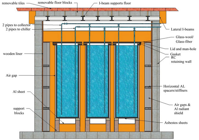
Figure 1. Cross-sectional elevation of hot-storage unit.
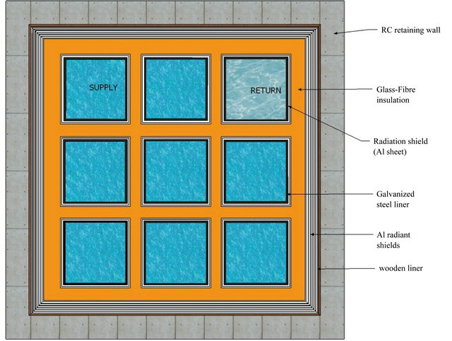
Figure 2. Cross-sectional plan cutting through horizontal mid-plane.
side air-gap of 10 - 20 mm. Thus any one tank may be lifted upwards and removed from the storage-unit separately without destroying the surrounding insulation or damaging neighboring tanks. The small width of the gap does not allow significant convective currents [9], therefore the only mechanisms for heat transfer would be conduction and radiation. The former is low because of the low thermal-conductivity of air, whereas the latter is held at bay by the low emissivity (high reflectivity) of the liner, and by another shiny aluminum plate cover on the insulation side facing the liner.
The air-gap also allows the installation of vapor detectors and temperature sensors. A sudden increase of their readings would indicate a leak in the nearby storage tank, causing an alarm to be triggered.
Suggested insulation material include common glasswool, glass fiber, or mineral-wool blankets all of which are widely available and cheap, and display a coefficient of conductivity k ≈ 0.04 W/(mK) [10]. More sophisticated materials with superior insulation properties include micro-porous insulation based on Pyrogenic silica with k = 0.022 W/(mK), at 200˚C, Silica Aerogels with typical k = 0.017 W/(mK) , and Silica Aerogels with Carbon Black displaying a conductivity as low as k = 0.004 W/(mK) [11]. It is remarked that condensation is not an issue here, as the whole structure is air-tight, the external desert air is typically exceptionally dry, and the high internal temperature in the insulation section results in very low relative humidity.
The thickness of insulation between the interior tank’s surfaces is 100 mm, whereas the thickness of insulation at the exterior surfaces is 500 mm. The insulation on the exterior tank walls wraps around all the tanks, as shown in Figure 2. Following the external surface of the insulation are 19 concentric radiation shield plates formed from polished aluminum plates approximately 1 mm thick and separated by an air gap of approximately 9 mm. These introduce an effective thermal resistance between the insulation material and the 50 mm thick timber covering the reinforced concrete side-walls.
The heat transfer across the thermal shield is by both conduction and radiation, but not convection because of the small width of the air-gap. All the aluminum surfaces are assumed to display an emissivity of 0.07, which lies mid-way between the 0.04 - 0.1 range typical of polished commercial plates. The radiation shield is much more effective as a thermal resistances at low temperatures than at higher ones, because of the dependence of radiation on the 4th power of temperature, and the lower conductivity of air at lower temperatures; thus it has been placed after the insulation material and not before it. The timber concrete cover is originally the internal wall of the wooden mold (frame) built for pouring the reinforced concrete retaining walls during construction and left there to exploit its good insulation properties. The reinforced concrete retaining walls are each 250 mm thick.
Each tank is supported independently on four 0.1 m square reinforced concrete blocks which transfer the weight down to a 300 mm reinforced concrete slab, Figure 1. A 50 mm thick asbestos plate separates the blocks from the tank liner. Below the tank liner, a 0.30 m airgap is present which is followed by 450 mm of insulation. Although the air-gap is large, convection currents may be neglected because the top surface is the hotter one resulting in a stratified density field; hence this gap is expected to contribute to the bottom insulation. Again instrumentation is placed in this gap to provide advanced warning in case of a leak.
The top of the tank is closed by a stainless steel lid through which the hot-water supply and return pipes protrude. The lid is covered by 600 mm of insulation followed by a highly reflective aluminum plate. A 0.3 m air-gap separates the insulation from the hot-water storage roof unit; this gap does not contribute significantly to insulation of the roof because of the strong convective currents, but is introduced for ease of installation and accessibility of bends and valves; hence the relatively larger thickness of top insulation. The roof is formed from removable reinforced concrete blocks, supported on steel I-beams and covered by detachable tiles, Figure 1.
Figure 2 shows that there is a total of 9 identical tanks. During operation some of the tanks may store heated water from the solar collector at 180˚C, whereas others should store returned water from the absorption chiller at 170˚C. Supply and return pipes, with control valves, connect the individual tanks to the solar collector and chiller-generator. During hours of chiller operation on stored energy, supply water at 180˚C will be drawn from the supply water tanks and returned at 170˚C to the return water tanks. Whereas during hours of solar energy storage, previously returned water from chiller at 170˚C will be drawn from the tanks and fed to the solar collector system to be heated to 180˚C before being returned to a supply tank for subsequent use in the chiller-generator. The supply and return tanks are constantly interchanged as one tank is emptied or filled. This system allows the use of a single storage unit for storage of both supply and return hot-water.
The volumetric capacities of the tanks are selected such that only eight of them provide the entire storage needs, the ninth being needed because during operation, the tank from which hot-water is drawn may be only partially filled; and so will be the tank through which the used water returns.
4. The Heat Loss Model
Although the ambient temperature varies throughout the day, and the temperature of the hot-water inside the tanks changes periodically from 170˚C to 180˚C and back, the thermal capacity of the storage unit is large and the processes are cyclic; therefore the variations with time may be neglected and a time averaged, steady-state heat transfer model is employed with the hot-water temperature, TH, being the average of the return and supply hot-water temperatures, i.e. TH = 175˚C. The ambient temperature is prescribed the daily average value, Tamb, for the hottest month of the year, which is when maximum storage capacity will be needed.
The heat loss mechanism involves all modes of heat transfer, i.e. conduction, radiation and convection. However, the most important in the current application is the conduction mode as it is the one posing the highest thermal resistance to the heat leak. In order to avoid having to compute turbulent, buoyancy driven flows within several isolated air gaps and water tanks, empirical results are employed to simulate the convective terms; thus freeing computational resources for a more accurate prediction of the conduction heat transfer. Both the convection terms and radiation terms are introduced as source terms to the fully three-dimensional, conduction equation with variable material properties as follows:
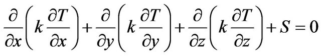 (1)
(1)
where k denotes the local value of the coefficient of conductivity, S represents radiation and/or convection source terms; x, y represent the two horizontal orthogonal Cartesian coordinate directions, measured outwards from the centre-line of the storage tank; and z represents the third Cartesian coordinate direction measured vertically downwards from the ground surface. Because of symmetry, the integration domain includes only one quadrant of the storage tank; however, it extends 60 m in the soil below the storage-unit bottom and 50 m beyond each side, thus creating a semi infinite soil volume embodying the storage tank. The top of the integration domain is bounded by the ground surface.
The finite volume method is employed to solve Equation (1) numerically, subject to the following boundary conditions.
4.1. Boundary Conditions
4.1.1. At the Internal Side-Boundaries (x = 0, y = 0)
Symmetry conditions are imposed, implying no heat flux.
4.1.2. At the Top-Boundary (z = 0)
This is the surface of the ground exposed to the ambient atmospheric air. A convective boundary condition is imposed, with an external heat transfer coefficient hou = 22.7 W/(m2K) and ambient temperature, Tamb = 35˚C. For sake of generality, the value of hou was ascribed the ASHRAE recommended standard value for summer weather [12], but a more specific value reflecting local ambient conditions would be more accurate.
4.1.3. At the Bottom and External Sides-Boundaries
These boundaries represent the extremities of the integration domain in the x, y, and z-directions. By default the model adopted here assumes that at steady state, all heat leakage from the storage unit eventually finds its way through soil and roof conduction to the top-boundary surface, and from there to the atmosphere. Thus the boundary condition at the side and bottom boundaries is that of no heat flow across the boundary.
This is the classical assumption adopted in the commonly used conduction shape factors [13], to calculate heat losses from buried objects close to the surface (e.g. pipes). However, this requires that the bottom and side boundaries are sufficiently far out from the heat source; an assumption which is verified here by comparing the results for two types of side and bottom boundary conditions; namely the default with zero gradient condition, and an alternative one with a specified temperature condition in which the temperature is set to Tamb.
For the standard design and conditions displayed earlier, the total heat loss rate from one quadrant of the unit, is calculated to be 152.01 W for the zero gradient boundary condition, and 152.02 W for the boundary-value condition; differing by only 0.0066%. For the boundary-value formulation, approximately 91% of the total heat dissipated escapes from the top surface, whereas around 9% escapes through the bottom and sides boundary. However, the heat dissipated at the storage-unit boundaries is barely affected, which demonstrates that the integration domain is large enough for the results not to be affected by the conditions at the far out boundaries. This was also confirmed by extending the integration domain 50 m in all directions and checking that the calculated heat loss from the storage-unit was practically unaffected.
4.2. Convergence and Grid-Independence
Due to the non-linearity of the radiation terms, and the temperature dependence of the convection heat transfer coefficients, iterative solution is necessary. An external iteration loop is employed to derive the temperature difference across the top and bottom air-gaps, and between the bulk of water at TH and the liner surfaces; this loop requires typically 4 - 5 iterations. An internal loop is employed to handle the radiation terms non-linearities, requiring approximately 40 iterations for full convergence.
Convergence is indicated by both conventional and non-conventional criteria. The former include the reduction of the sum of residuals of the control-volume equations to below a certain specified tolerance level, simultaneously with another tolerance level for the incremental change in the local temperature values per iterations. The latter, which is more problem specific, monitors the difference between the computed heat flux crossing the boundaries of the storage unit, and that dissipated from the ground surface to atmosphere. Inner iterations are stopped when the magnitude of this difference is typically less than 0.07%.
Grid independence checks are performed by comparing results obtained from coarser and finer grids. The coarser grid employs 84 × 84 × 87 grid control-volumes in the x, y and z-directions, respectively; whereas the finer one employs double this number of control-volumes in each direction, half the grid spacing being used in all regions. The results for the heat loss at the storage unit outer surface agree within 0.00033%, which is an extraordinary small difference, indicating no significant grid-dependence.
4.3. Modeling Source Terms and Interfaces
The treatment at the material interfaces and the modeling of source terms requires special considerations which are presented here.
4.3.1. Vertical Liner-Gap
Each tank liner is separated from the surrounding sidewall insulation by a thin air-gap of the order of 10 - 20 mm; thus convection currents within the air-gap may be neglected [9], and heat is assumed to cross the gap by conduction and radiation only. The thermal resistance between the near liner water grid-node at temperature TH, and the opposite insulation node at temperature Tins, is the sum of the convective resistance on the water side, the combined radiation-conduction resistance across the air-gap, and the conductive resistance within the insulation material. The heat flux across the liner, q, is thus expressed by:
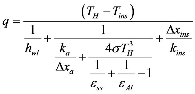 (2)
(2)
where hwl is the convective heat transfer coefficient at the water liner face, Dxa is the thickness of the liner air-gap, Dxins is the depth of insulation from face to first insulation grid-node, and ka, kins are the thermal conductivities of air and insulation material, respectively. εss and εAl represent the emissivity of the liner material (steel) and insulation cover material (Aluminum), respectively. The value of hwl is derived from the following empirical equation for turbulent natural convection on a vertical plate [14]:
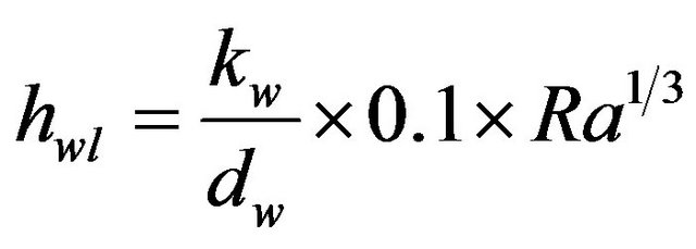 (3)
(3)
where kw is the thermal conductivity of water, dw is the depth of the tank and Ra is Rayleigh’s number. The mean temperature difference, DTwl, between the hot water bulk temperature, TH, and the inner liner surface is unknown a priori; thus an initial guess is used to start the solution and this value is improved iteratively based on the calculated value of the heat lost, according to:
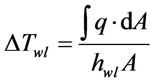 (4)
(4)
where the integral is performed over the entire vertical liner surface area, A.
4.3.2. Radiation Shield
The radiation shield is composed of several closely spaced parallel aluminum plates, filling the space (0.2 m) between the insulation external-surface and the wooden-frame internal surface. As an exception, the control-volumes at the two interfaces are filled on one side of the grid-node by one material and on the other side by another. This is in order to have the grid-nodes flush with the interface surface and therefore avoid interpolation of surface temperatures required for radiation heat transfer calculations. The same treatment is applied to all air-solid/liquid interfaces for which radiation heat transfer is calculated.
Since the spacing between successive plates is small (~10 mm), buoyancy driven convection currents may be neglected [9], and only radiation and conduction heat transfer needs to be considered. All plates are assumed to display the same emissivity, εAl, including the sheets covering the insulation-material and the wooden-frame.
Denoting the former by the index “0” and the latter by (n + 1), and assuming uniform air conductivity, k, throughout, it is easy to show that the heat flux flowing across the radiation shield is expressed by:
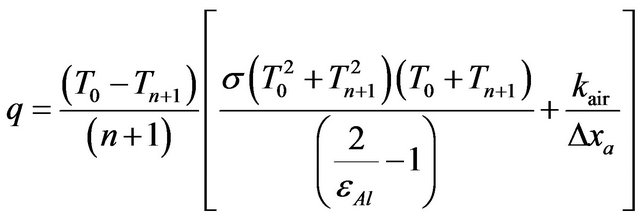 (5)
(5)
where kair is the mean air conductivity, Dxa is the air-gap between successive shield plates, and n is the number of internal plates. The first term in the square bracket is the source term S, whereas the second one is the regular conduction term.
4.3.3. Bottom Air-Gap
Heat transfer across the air-gap separating the liner bottom from the insulation surface occurs mainly by radiation and conduction. This is because, the hotter surface (the tank bottom plate) is the one on top, resulting in a stratified density field with negligible convection currents [15]. The air is assumed to be transparent to radiation, and the radiative heat exchange occurs directly between the liner bottom grid-node and the opposite insulation surface grid node.
4.3.4. Air-Space above Water-Surface
The space between the surface of the hot water and the tank lid is occupied by a thin layer of air, of thickness 10 - 20 mm. This yields a Rayleigh number which is too small for convective effects to be significant; the main mechanism of heat exchange across the gap being radiation and conduction. The thermal resistance between the bulk of hot water at TH and the first insulation grid node at temperature Tins is thus the sum of the convective resistance at the water surface, the combined radiation and conductive resistance in the air-space, and the conductive resistance from insulation surface to first internal grid-node, yielding:
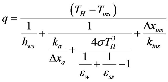 (6)
(6)
where εw denotes the emissivity of the water surface, and hws the heat transfer coefficient, calculated from the following empirical relation for convective heat transfer for a cooled plate facing downwards [14]:
 (7)
(7)
The temperature difference, DTws, appearing in Ra definition is the difference between TH and the air-water interface surface temperature; it is unknown a priori, thus an initial guess for the mean temperature difference, DTws is used to start the solution and improved iteratively based on the calculated value of the heat lost, according to:
 (8)
(8)
where the integral is performed over the entire water surface area, A.
4.3.5. Top Air-Gap
The heat transfer across the top air gap occurs by conduction, convection and radiation. An effective conductivity, ke is employed to evaluate both the convective and conductive contributions, according to the following empirical equation for natural convection in enclosed spaces confined between parallel horizontal surfaces [15]:
 (9)
(9)
where the temperature difference in the Ra definition is the mean difference between the insulation-layer topsurface-temperature and the roof bottom surface temperature, both of which are an outcome of the solution; therefore ke is corrected iteratively to employ the latest predicted temperatures. Radiation heat exchange is assumed to occur directly between the insulation top surface and the bottom roof surface, with air being assumed to be transparent to radiation.
5. Display of Results
Figure 3 displays the temperature distribution over the entire y = 0 symmetry plane. Because of symmetry the integration domain contains only one quadrant of the storage-unit, which is displayed at the top left corner.
The diagram on the left employs a color code to reveal the magnitude of the local temperature, whose key is displayed at the center of the figure. A solid dark line outlines the outer surface of the reinforced concrete, which forms the boundaries of the storage-unit. The diagram displays the vast volume of soil surrounding the storage-unit which is included in the solution domain in order that the boundaries do not obstruct the heat flow. It also reveals that the high temperature region is confined to the immediate neighborhood of the tanks, and that the surrounding soil temperature is very close to the soil surface temperature; this is attributed to the high thermal resistance within the proposed storage-unit.
The diagram on the right shows the corresponding isotherms, plotted employing 100 equally spaced temperature intervals between the surface temperature (35˚C) and the hot-water temperature (175˚C); moreover the isotherms are colored according to the color code employed in the left drawing. Immediately below the hot water tanks, the isotherms are very closely spaced, but they widen rapidly in a short distance, indicating quickly diminishing vertical gradients and therefore limited downward penetration of heat into the soil.
Near the ground surface, the isotherms reveal large gradients only close to the storage-unit, whereas further out the gradients rapidly die out implying that the heat dissipated to the atmosphere becomes negligibly small.
Figure 4 displays a ten folds enlargement of Figure 3, in the region surrounding the storage unit. The outlines of the different materials forming the storage unit are also displayed.
The left diagram reveals that the major temperature drop in the storage unit occurs within the insulation material alone; particularly so for the vertical sides. However, the soil temperature immediately below the reinforced concrete bottom of the storage tank is notably higher than that on the outside of the reinforced concrete side walls, despite the insulation thickness being almost the same, and the concrete thickness being larger for the bottom. This is attributed to the higher thermal resistance of the thermal radiation shield compared to that of the air-gap; the latter offering less radiation resistance because of the higher temperature and lack of shielding surfaces.
The right diagram displays a closer spacing of the isotherms in the soil at the bottom of the storage unit than on the sides, indicating higher heat fluxes and losses from the bottom of the unit. Thus increase of insulation
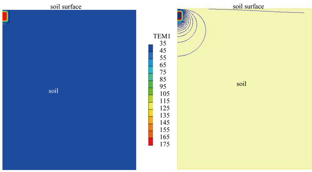
Figure 3. Temperature distribution over entire symmetry-plane.
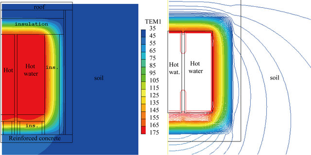
Figure 4. Enlargement of cross-sectional elevation near storage unit.
thickness at the tank bottom may be justified.
On the other hand, the temperature immediately above the top insulation is seen to be very close to that of the surface, indicating relatively small losses from the top; hence some saving of insulation material there may be justified. It is remarked that the gradients at the roof top, displayed in the right diagram, are still larger than those on the sides; however, this is because of the lower conductivity of the roof-top material compared to soil.
Figure 5 reveals the corresponding cross-sectional plan view, for a horizontal plane passing mid-way through the hot-water tanks. Again it is revealed that most of the temperature drop occurs in the insulation material, followed by the radiation shield.
6. Investigations
Investigations where conducted to evaluate the effect of ground surface-temperature, soil conductivity, insulation-material conductivity and number of radiation-shield plates on heat-loss from the storage-unit.
The heat-loss is expressed as the percentile of heatloss per day to maximum energy storage, calculated as the product of the mass of water stored in 8 tanks × water specific-heat × 10˚C (temperature difference between solar collector hot-water outlet and inlet).
Figure 6 displays the loss percent as a function of ground surface temperatures ranging from 20˚C to 45˚C, which is the typical range expected in the Arabian desert. It is seen that the heat loss varies between 5.2% - 6.2% of maximum storage, representing a deviation of approximately 10% about mean which is substantial. Moreover, the profile is highly linear. Since the hot water temperature is fixed at 175˚C, this indicates a nearly constant thermal resistance between hot-water and ground-surface, despite several air-gaps introducing radiation and convection heat transfer, and internal free-convection within the water-tanks, all of which are temperature dependent. This is attributed to the conduction resistance being dominant.
Figure 7 displays the variation in heat loss with soil conductivity, in the range of 1 - 2.5 W/(m2K), the limits corresponding to dry sand and saturated soil, respectively. Also displayed is the upper limit for artificially high conductivity (k = 1000W/(m2K)) which represents the case of zero soil thermal resistance. It is revealed that the soil conductivity has little effect on the heat loss; the total heat loss varying by only 0.2% in the normal soil conductivity range, and that in the limiting case without any soil resistance the heat loss is only 0.26% higher than the minimum.
Figure 8 shows the variation of heat-loss % with number of internal radiation shield plates, for an overall gap width of 0.20 m. The variation is small, the loss dropping from 5.7% to 5.625% when the number of internal plates increases from 9 to 19; moreover the slope of the curve indicates a decreasing return with increase of number of plates. The latter can be explained by the loss in the plates air-gap being the sum of conduction-loss and radiation-loss, and the former is essentially independent of the number of shield plates since the gap is small enough for convection effects to be negligible. Hence as the number of plates tends to infinity the loss tends to a constant. Moreover, the radiation component of Equation (5) reveals that the relation between the heat loss and number of shield plates is hyperbolic, i.e. the product  is a constant for a given T0 and Tn+1.
Figure 9 displays the effect of varying the thermal conductivity of the insulation material on heat loss; the range of conductivity varies between 0.021 W/(m2K) for microporous pyrogenic silica insulation to around 0.057 W/(m2K) for Fiber-glass blankets. Two sets of data are
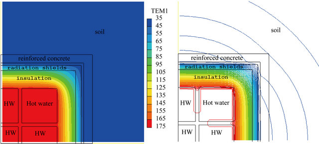
Figure 5. Enlargement of cross-sectional plan at horizontal mid-plane.
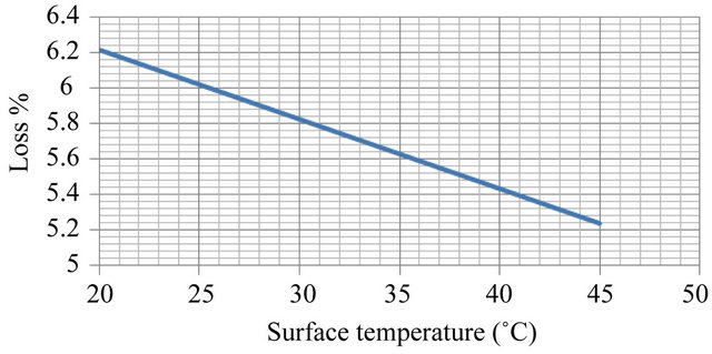
Figure 6. Effect of surface-temperature on heat loss.
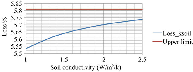
Figure 7. Effect of soil conductivity on heat loss.
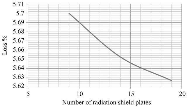
Figure 8. Effect of number of shield plates on heat loss.
presented; one set displays the results for the design displayed in Figures 1 and 2 with the radiation-shield inserted, while the other displays the results when the radiation-shield is removed and its volume is filled with the

Figure 9. Effect of conductivity of insulation material on heat loss.
same insulation material used throughout the unit.
It is seen that with radiation shield, the heat loss increases almost linearly with increase of conductivity, and that it varies between 3.6% for the lowest conductivity to 7.1%, for the highest, i.e. almost double. It is clear that highest storage efficiency requires employing the best insulation material. The linearity of the loss-conductivity relation, and the relatively large magnitude of the loss-variation, imply that by far the most important thermal resistance in the unit is the conduction resistance presented by the insulation material; this result is also confirmed by the previous investigations for radiation-shield and soil conductivity.
Comparison of the design with radiation shield against that without, reveals that for insulation materials with k > 0.028 W/(m2K) the design with radiation-shield is superior; for lower conductivities the design is inferior, but the cost of this high quality insulation is likely to be considerably more expensive than the radiation shield, and the improvement may not be worth it.
7. Discussion, Summary and Conclusions
The paper presents a simple design for solar energy storage in the intermediate temperature range suitable for the desert environment. The storage unit is built below ground, freeing valuable residential space, and is environmentally friendly, safe, robust, requires minimum maintenance, and is easy to monitor and repair on site, even in a desert environment. Moreover, it achieves storage efficiencies ranging from 96.7% for the most efficient design considered with an environmental temperature of 45˚C, to 91.8% for the least efficient design with an environment temperature of 20˚C; a typical efficiency of 94% - 95% may be expected for an environmental temperature of 35˚C.
An efficient and effective model is developed for the computation of the heat losses, which adopts the full three dimensional heat conduction equation with variable properties as the fundamental governing equation, simultaneously with simplified source terms for radiation and convection. The calculations show that the conductive thermal resistances of the materials far outweigh the convective and radiative ones, thus justifying the simplifications introduced.
The results show that the conductivity of the insulation material is the most important parameter determining storage efficiency. Higher efficiency could also be obtained by increasing the thickness of the insulation material; however the improvement is not expected to be linear as it would lead to an increase in the external dimensions of the storage unit which would lead to an increase of surface areas through which heat seeps out to the environment.
The optimum material thickness and type to use is a trade-off between insulation material cost savings and other capital cost savings. The latter include construction and land use costs, and the cost of solar collection equipment and roof area usage. Thus the optimum material choice, may well be site dependent; however, in view of the great reduction in the heat loss obtained by improved insulation material properties, and that the insulationmaterial is only one component in the structure of the storage-unit and possibly not the most expensive, the use of highest quality insulation material is likely to reap its benefits.
8. Acknowledgements
This work was sponsored by the King Abdulla University for Science and Technology, through the Integrated Desert Building Project at AUC.
REFERENCES
- M. A. Serag-Eldin, “Thermal Design of a Modern, AirConditioned, Single-Floor, Solar-Powered Desert Home,” International Journal of Sustainable Energy, Vol. 30, No. 2, 2011, pp. 121-141. doi:10.1080/1478646X.2011.562607
- A. Gil, M. Medrano, I. Martorell, A. Lazaro, P. Dolado and B. Zalba, “State of the Art on High Temperature Thermal Energy Storage for Power Generation. Part 1. Concepts, Materials and Modellization,” Renewable and Sustainable Energy Reviews, Vol. 14, No. 1, 2010, pp. 31-55. doi:10.1016/j.rser.2009.07.035
- M. Medrano, A. Gil, I. Martorell, X. Potau and L. F. Cabeza, “State of the Art on High-Temperature Thermal Energy Storage for Power Generation. Part 2. Case Studies,” Renewable and Sustainable Energy Reviews, Vol. 14, No. 1, 2010, pp. 56-72. doi:10.1016/j.rser.2009.07.036
- M. A. Serag-Eldin, “Effect of Environmental Properties on Selection of Absorption Chiller and Thermal Storage for a Desert Home,” Proceedings of the 5th International Exergy, Energy and Environment Symposium, IEEES-5, Luxor, 12-15 December 2011.
- M. A. Serag-Eldin, “Lowering the Sink Temperature of a Desert Solar Air-Conditioning System,” In: C. A. Brebbia and E. Beriatos, Eds., Sustainable Development and Planning V, WIT Press, Southampton, 2011, pp. 227-238. doi:10.2495/SDP110201
- M. A. Serag-Eldin, “Analysis of a Roof-Top CLFR to Drive a Solar Air-conditioning System for a Desert Home,” Proceedings of the 5th International Exergy, Energy and Environment Symposium, IEEES-5, Luxor, 12-15 December, 2011.
- D. R. Mills and G. L. Morrison, “Compact Linear Fresnel Reflector Solar Thermal Powerplants,” Solar Energy, Vol. 68, No. 3, 2000, pp. 263-283. doi:10.1016/S0038-092X(99)00068-7
- M. A. Serag-Eldin, “Modeling the Energy Systems in a PV Powered Two Floor Desert ZEH,” In: G. M. Carlomagno and C. A. Brebbia, Eds., Computational Methods and Experimental Measurements XV, WIT Press, Southampton, 2011, pp. 267-278.
- J. F. Kreider, P. S. Curtis and A. Rabl, “Heating and Cooling of Buildings: Design for Efficiency,” 2nd Edition, CRC Press, London, 2010, p. 259.
- “Engineering Tool-Box, Thermal Conductivty.” http://www. engineeringtoolbox.com/thermal-conductivityd_429.html
- Microstructured Materials Group, “Silica Aero Gel,” Lawrence Berkeley Labs. http://www.sps.aero/key/TSA-009_White-Paper_silics-Aerogels.pdf
- American Society of Heating, Refrigerating and Airconditioning Engineers, “ASHRAE Fundamentals Handbook,” 2009.
- J. P. Hollman, “Heat Transfer,” 10th Edition, McGraw Hill International Edition, London, 2010, pp. 83-88.
- J. P. Hollman, “Heat Transfer,” 10th Edition, McGraw Hill International Edition, London, 2010, p. 334.
- J. P. Hollman, “Heat Transfer,” 10th Edition, McGraw Hill International Edition, London, 2010, p. 350.