Intelligent Control and Automation
Vol.06 No.01(2015), Article ID:53164,8 pages
10.4236/ica.2015.61001
Research on Workpiece Sorting System Based on Machine Vision Mechanism
Juan Yan, Huibin Yang
College of Mechanical Engineering, Shanghai University of Engineering Science, Shanghai, China
Email: aliceyan_shu@126.com
Copyright © 2014 by authors and Scientific Research Publishing Inc.
This work is licensed under the Creative Commons Attribution International License (CC BY).
http://creativecommons.org/licenses/by/4.0/


Received 14 November 2014; accepted 28 December 2014; published 13 January 2015
ABSTRACT
This paper describes industrial sorting system, which is based on robot vision technology, intro- duces main image processing methodology used during development, and simulates algorithm with Matlab. Besides, we set up image processing algorithm library via C# program and realize recognition and location for regular geometry workpiece. Furthermore, we analyze camera model in vision algorithm library, calibrate the camera, process the image series, and resolve the identify problem for regular geometry workpiece with different colours.
Keywords:
Machine Vision, Industrial Robot, Target Recognition, Image Processing

1. Introduction
With the development of society, enterprises have become increasingly demanding on production automation, so that more and more industrial robots have been used in automated production lines. For example, in order to enhance operational efficiency in modern logistics distribution centers and to improve the efficiency of large- scale centralized distribution to reduce operating costs, as the core equipment distribution center and the main operating procedures, sorting systems and sorting operation efficiency and technology are increasingly by theorists and engineering concern. Another example is the tool change robot in the machining center. Compared to ma- nual tool change method, this tool works more quickly and more accurately, greatly reduces tool change time and increases production efficiency. In the automotive industry, due to the auto parts more complex vehicle bodies, in many cases on the body cannot use manual welding. Currently, automobile manufacturers utilize a lot of body welding robots to improve product quality and to reduce the labor intensity. Visibly, doing the work on the production line with industrial robots is an inevitable trend.
Machine vision technology uses cameras and computers to simulate human vision features, which are widely used in electronics, aerospace, automotive and automotive parts manufacturing industry, the pharmaceutical industry and electronics fields [1] . In the traditional production line, sorting artifacts with industrial robots usually uses teaching methods or offline programming operations. All the actions and placements, etc. should be strictly preset. Once the working environment or condition changes, it will affect the efficiency and accuracy of crawling robot, unable to meet the high-speed production of large quantities. Introduction of machine vision in industrial production can greatly improve productivity and reduce costs. Industrial machine vision technology based on sorting system with high detection speed, high reliability, and high real-time, compared to traditional mechanical sorting, is more intelligent, more efficient and has other irreplaceable advantages.
This paper researches the sorting system based on the machine vision and the methods of camera calibration. The straight linear method is used and the system is simulated by Matlab. It also studied the correlation of image processing algorithms, combined thresholding proposed centroid location method to solve the different colors of regular geometric shape of the workpiece recognition problem. Threshold segmentation and edge detection method can lock the workpiece area; centroid location can accurately locate the geometric center of the workpiece. And this integrated approach can effectively solve the regular geometric shape of the workpiece sorting problem.
2. Sorting System Based on Machine Vision Hardware Architecture Artifacts
In this paper, the mechanical axis motion platform, is built on the work of sorting machine vision systems. Overall system structure is shown in Figure 1.
The hardware platform consists of mechanical three-axis motion platform, camera platforms, PC and motion control unit, four major components. Hardware platform package sorting system is shown in Figure 2.
Mechanical three-axis motion platform: Using screw-nut mechanism, while the linear guide linear motion needs as a guide and support. The system uses a servo motor drive: although the control unit is complex, the high repeat accuracy, no step phenomenon and no cumulative error [2] .

Figure 1. Piece sorting system structure based on machine vision.

Figure 2. Workpiece sorting system based on machine vision hard- ware platform.
Camera Platform: Camera platform unit is mainly constructed by MV-2000UC camera and light source com- ponents. Hanging bracket role monocular camera is to obtain the experimental stage of the video image of the workpiece. White LED surface light source provides light for digital cameras captured images. The light will be fixed at the top of the workpiece in order to eliminate the shadow of the workpiece itself.
PC: Using existing laboratories as a PC, since the development environment is good, fast, easy to operate and low cost. At that time with respect to the IPC, its anti-interference ability and stability is poor, such as teaching or laboratory for stable work environment occasions. PC camera platform receives the experimental stage to obtain a video image of the workpiece using the vision system to identify the target species, the centroid of the workpiece is then calculated, and finally the image according to the relationship between the coordinate system and the object coordinate system, the calculated position of the target relative and direction, and then passes the information parameter to the control unit.
Motion Control unit: mainly control the composition of the cabinet and robots. It is responsible for the para- meters analyzing, then the robot-related operations and finally the completion of the target workpiece sorting grab and place.
3. Camera Calibration
Camera calibration is one of the important parts in machine vision [3] . Calibration includes calibration camera and visual systems. First of all based model of the camera, and then to establish the relationship between the coordinate system, and finally through the calibration can establish the correspondence between image pixels and the spatial three-dimensional coordinates [4] . Workpiece sorting system is based on machine vision. The camera calibration as a key link to other related work is a prerequisite for the smooth conduct of the direct impact on subsequent sorting processes. Camera calibration process is based on the model of the camera imag- ing process to solve internal and external camera parameters, and these parameters determine the correspon- dence between the image pixel point and three-dimensional coordinate space.
There are many ways in camera calibration, the current methods commonly used in machine vision are direct linear method, perspective projection matrix method, Zhang Zhengyou France, the two-step camera calibration method. For the facts of relatively stable laboratory and low interference environment, this paper chooses the direct linear method, which is characterized by convenient computing but less accuracy. It is difficult to be pre- cise shooting environment complex self-correcting. DLT method called direct linear method, by Abdel-Aziz and Karara and was first proposed in 1971 [5] . This method does not consider the non-linear distortion of the camera, getting the relevant parameters of the camera by directly solving a set of linear equations. It acquires pinhole imaging model for the study, ignoring specific intermediate imaging process and using a 3 × 4 order matrix to represent a direct correspondence between the point and the two-dimensional space object image point. The linear transformation matrix is with only a difference of a perspective matrix scale factor. Providing space point 
 coordinates in the camera coordinate system of
 , the camera will capture the image on the CCD imaging plane, which is provided for the image point coordinates
  corresponding to the image pixel coordinates
 .
.
By the world coordinate system to the camera coordinate system, using the following formula rotation―trans- lation conversion formula described:
 (1)
(1)
where in  is a rotation matrix,
  is the translation matrix. In the case where distortion is not considered (i.e., an ideal perspective projection), the image coordinates of the camera coordinate system is described by the following formula:
 (2)
(2)
In the image processing, is often used in image coordinate of the pixel as a unit, so to convert the image coordinate system to the coordinate system of the pixel, i.e.
 (3)
(3)
Without considering the various types of the imaging by the specific process, can be obtained:
 (4)
(4)
where,  of the three-dimensional world coordinate space points,
  coordinates of the corres- ponding pixel, rij is a perspective view of elements of the transformation matrix. It contains three equations, finishing eliminates, obtain the following two linear equations on people rij:
 (5)
(5)
 (6)
(6)
This equation describes the relationship between the two three-dimensional world and the corresponding points between image points. If the three-dimensional world coordinates and the corresponding image coor- dinates are known, the transformation matrix regarded as unknown, then there will be a total of 12 unknowns. For two equations above each object point has, in general, can be set , then there will be a total of 11 unknowns. Taking six goals can get 12 points a overdetermined equation Using the least squares method des- cribed above can easily find solution of linear equations [6] . Using more points, we make much more than the number of equations number of unknowns, using the least squares method for solving can reduce the impact of errors caused by the perspective transformation matrix obtained after its decomposition can get cameras inside and outside the parameters.
Based on the direct linear method was calibrated to the camera. Put the calibration paper on a suitable position in the robot coordinate system, as shown in Figure 3. Cross figure crosshairs for the world coordinate system. Only a simple translation of the relationship is needed between it and the robot base coordinate system, i.e., calculating the target position in the world coordinate system, then subtracting a certain shift amount and finally obtaining the target based on the robot base in the standard position.

Figure 3. Camera calibration chart based DLT.
Corner extraction algorithm using corner point data is shown in Table 1.
On the Matlab model with a blue asterisk plotted coordinates of each point (real value), the table on each corner point coordinates a left multiplication result (calculated) M-1 obtained plotted with a green plus sign, as shown in Figure 4.
The verification result from Figure 4 is that, by using direct linear method in this system, the calibration results is accurate, easy to calculate and close to actual value. Besides, the calibration results are also good, which provides a reliable foundation for accurate positioning of the workpiece in a sorting system.
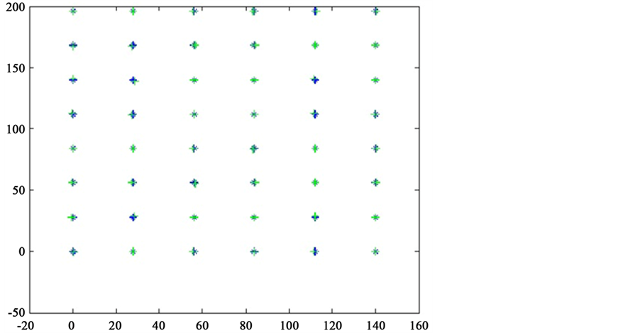
Figure 4. Camera calibration results based DLT.

Table 1. Angular point data table.
4. Thresholding Segmentation
This design uses machine vision technology, the different colors of the workpiece intelligent sorting rules. When the camera calibration is completed, after the pixel coordinates to the scenecoordinate correspondence to obtain the target, will be on the video image is processed by computer.
First, the camera image acquired in the target workpiece is detected. Target detection is extracted from the image portion of interest, i.e., the image segmentation; the image processing to the image analysis is a key step. At present, a lot of image segmentation methods, such as thresholding method, edge detection and region extraction method. In this paper, we use the thresholding method and edge detection method to detect the target workpiece.
Thresholding as the most common color distinction is a region-based image segmentation technique. Briefly, image segmentation threshold is transformed to a color image to grayscale, the first grayscale range of an image to determine the gray value threshold, then the image of the gray value of each pixel with this threshold value, and are classified according to the size of the result of the comparison, based on the threshold values of all the pixels in the image is divided into two areas.
A pair of the original image  is taken to define a single threshold value
  of the divided
 (7)
(7)
In the actual case, the difference between the image of the target workpiece and background brightness is small, so the threshold needs to be adjusted manually. Figure 5 shows the use of maximum between-class va- riance method combined with manual adjustment method in Matlab to finalize the process threshold.
 (a)
(a)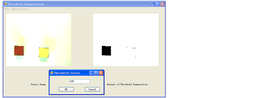 (b)
(b)
Figure 5. Threshold segmentation results. (a) When the threshold T to 80 threshold segmentation results; (b) When the threshold T to 100 threshold segmentation results.
From the segmentation results can be seen, when the threshold of T is 100, it’s the best segmentation, can accurate segmentation of the target range of workpiece, which proves Ostu method combined with manual adjust- ment is the most suitable way for this system.
5. Determine the Centroid
In the sorting operation of the workpiece, the workpiece needs to be identified for positioning, the general centroid coordinates describing the location information of the workpiece. But the calculation method for multi- target centroid such as starting algorithms geometric center of the target group, the calculation is more com- plicated; through rows of pixels accumulating and averaging roughly centroid location, can not meet the precise positioning. According to the characteristics identified herein workpiece shape rules proposed rule graphics centroid location method [7] .
When the function is applied to shape analysis, suppose there are binary function:
 (9)
(9)
Take  as the moment of order. The moment for
  digital image
 ,
,  is defined as:
 (10)
(10)
0-order moment is the area of the sum of the image gray,  values represent object binary image, if used to standardize an order moments
  and
and , we get the coordinates of the object’s center of gravity
 .
.
 (11)
(11)
For binary images, grayscale only 0 and 1, the focus is the centroid. Finally, the first moment  and
and  is divided by zero-order moments to get the coordinates of the center of mass of the object:
 (12)
(12)
After tests it is proved that the algorithm is simple and effective and is suitable for any graphics.
In this paper, the workpiece has been recognized as a rectangular, triangular, circular or a regular shape of the workpiece. The program is written in C#, in an ideal environment, workpiece recognition results are shown in Figure 6.
The rule workpiece centroid recognition results of Figure 6 demonstrates that, it is simple and efficient to adopt rule centroid locolization algorithm and is suitable for any graphic. Besides, programming is simple, re- cognition is speedy and recognition results are accurate.
6. Conclusions
This paper describes the main algorithm in the industrial sorting machine vision technology used in the system, using thresholding to detect the target work area and describe the target workpiece position information com- bined centroid location method. The recognition algorithm is programmed in MATLAB environment to conduct a simulation algorithm and it is developed using C# rule artifacts recognition software. According to the results obtained, to identify the robot reaches the top of the target number of pulses required to send to the motion control card, by motion control card for controlling the motor and the drive to achieve sorting purposes.
The results show that the practical application of technical methods discussed in this article is simple and effective. The sorting system identifies the type of workpiece correct rate of 100%, error of the target location is less than 5 mm, and further validates the feasibility of the system for robot.
 (a)
(a) (b)
(b)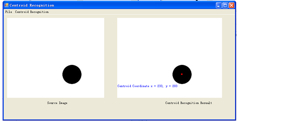 (c)
(c)
Figure 6. Rule workpiece centroid recognition results. (a) Rectangle centroid recognition results; (c) Triangle centroid recognition results; (c) Circular centroid recognition results.
References
- Zhuang, K.L., Wang, J.Z. and Zhou, J. (2011) Application of Machine Vision Technology in Terms of Angle Detection. Equipment Manufacturing Technology, 4, 9-11.
- El Masry, G., Cubero, S. and Molto, E. (2012) In-Line Sourting of Irregular Potatoes by Using Automated Computer- Based Machine Vision System. Journal of Food Engineering, 112, 60-68. http://dx.doi.org/10.1016/j.jfoodeng.2012.03.027
- Liu, Z.Y., Zhao, B. and Zou, F.S. (2012) Machine Vision Technology in the Sorting of the Workpiece. Computer Appli- cations and Software, 29, 87-91.
- Quan, H.H. and Zhang, L.P. (2007) Research on Machine Vision-Based Assembly Line Parts Recognition. Modular Machine Tool & Automatic Manufacturing Technique, 12, 58-60.
- Forsyth, D.A. and Ponce, J. (2002) Computer Vision: A Modern Approach. Prentice Hall, New Jersey.
- Shapiro, R. (1976) Direct Linear Transformation Method for Three-Dimensional Cinematography. Research Quar- terly, 49, 197-205.
- Ou, X.Y., Hou, X.Z. and Zheng, K. (2012) Machine Vision Based Automatic Teaching System of Six DOF Robot. Ma- nufacturing Automation, 34, 1-4.