Materials Sciences and Applications
Vol.4 No.10(2013), Article ID:37416,10 pages DOI:10.4236/msa.2013.410071
Bandwidth Enhancement of RMPA Using 2 Segment Labyrinth Metamaterial at THz
![]()
1Faculty of Electronics and Communication, Guru Tegh Bahadur Institute of Technology, New Delhi, India; 2NIT Patna, Bihar, India.
Email: paru.dawar@gmail.com, asok.de@gmail.com
Copyright © 2013 Parul Dawar, Asok De. This is an open access article distributed under the Creative Commons Attribution License, which permits unrestricted use, distribution, and reproduction in any medium, provided the original work is properly cited.
Received August 6th, 2013; revised September 8th, 2013; accepted September 17th, 2013
Keywords: Antennas; Metamaterials (MTMs); Negative Index Material; Negative Refraction; RMPA; MNG; HFSS
ABSTRACT
The past few years have been very eventful with respect to the evolution of the concept and implementation of “lefthanded materials (LHMs)”. This paper elucidates antenna parameter optimization using 2 Segment Labyrinth metamaterial embedded in antenna substrate at high frequency (THz). Ansoft HFSS has been used to design and analyse the RMPA (rectangular microstrip patch antenna) with design frequency 9.55 THz and operating range of 8.55 THz to 10.55 THz having RT Duroid (εr = 2.33) as substrate material. Magnetic properties of labyrinth resonator have been used to mathematically demonstrate the negative refraction. Nicolson Ross Wier (NRW) method has been used to retrieve the material parameters from transmission and reflection coefficient. Upon incorporation, bandwidth widens to around 4% and VSWR improves by approx 1.5%.
1. Introduction
“Metamaterials” (MTMs) are engineered to modify the bulk permeability and/or permittivity of the medium. They are realized by placing periodically the elements of size less than the wavelength of the incoming electromagnetic wave. This results in “meta” i.e. “altered” behavior or behavior unattainable by natural materials. Slight changes to a repeated unit cell can be used to tune the effective bulk material properties of a MTM, replacing the need to discover suitable materials for an application with the ability to design a structure for the desired effect [1-5]. Examples of MTMs are single negative materials (SNG) like ε negative (ENG) which have effective negative permittivity and μ negative (MNG) which have effective negative permeability, and double negative materials (DNG) [6].
It is worth recalling that negative values of permittivity are inherently bandlimited phenomena and such a condition can hold only at a certain frequency (accompanied with imaginary part of permittivity). The frequency, at which absolute polarizability becomes infinite and real part of permittivity is value “−2”, is called Frohlich frequency [7]. Particle shape has effect on the value of negative permittivity corresponding to Frohlich resonance. The geometry of negative permittivity particle has a strong effect on its surface plasmonic properties.
The past few years have been very eventful with respect to the evolution of the concept and implementation of “left-handed materials (LHMs)”. The cross product of E and H is proportional to the k vector and the E or H field. These vectors follow the right hand rule. Power flow is described by the Poynting’s Vector (S). The material values of particular interest to the electromagnetics community are the values of permittivity, ε, and permeability, μ. Taken together, ε and μ determine the speed of electromagnetic propagation through a medium and the square root of their product determines the refractive index (n). A real wave vector indicates a propagating wave, while an imaginary wave vector indicates attenuation (an evanescent wave). Therefore, upon entering a medium with altered material parameters, i.e. negative ε and μ, the group and phase velocities have opposite signs and are antiparallel, indicating that wave fronts move towards a source in this material creating a “backwards wave”. However, Poynting’s vector, which is defined by E × H, is still positive, power travels away from the source and causality is maintained. Thus the S vector follows the right hand rule, while the k vector is antiparallel to the S vector.
A fresh approach to microwave and optical devices presented itself with the interesting breakthrough in the area of MTMs at high frequencies. The software tool HFSS is used because it is a high performance full wave electromagnetic (EM) field simulator for arbitrary 3D volumetric passive device modeling [8]. It integrates simulation, visualization, solid modeling, and automation in an easy way to learn environment where solutions to 3D EM problems are quickly and accurately obtained [9].
Section 2 adumbrates RMPA design using Ansoft HFSS with design frequency 9.55 THz and operating range of 8.55 THz to 10.55 THz. Section 3 abridges the design of 2 segment Labyrinth MTM with resonant frequency 9.55 THz having RT Duroid (εr = 2.33) as substrate material and gives the mathematical proof of the designed MTM. Section 4 elucidates antenna parameter optimization using the proposed metamaterial. Section 5 concludes the paper.
2. RMPA Design
2.1. Design
RMPA i.e. Rectangular Microstrip Patch Antenna, as the name implies consists of a rectangular patch over a microstrip substrate as shown in Figure 1. Its major disadvantage is relatively low-impedance bandwidth which limits the field of application of these antennas. Bandwidth of RMPA can be improved by several methods available in literature e.g. use of thick substrates, addition of parasitic patches. The implication of such methods will not just increase the complexity of system, but will have adverse effect on gain of the antenna. Also, such methods involve changes in the parameters of the designed antenna. This calls for a novel technique to increase the bandwidth of antenna without altering its paramenters and without much affecting the antenna’s radiation properties. Henceforth, we introduce the metamaterial based antennas.
Transmission Line model represents RMPA as two
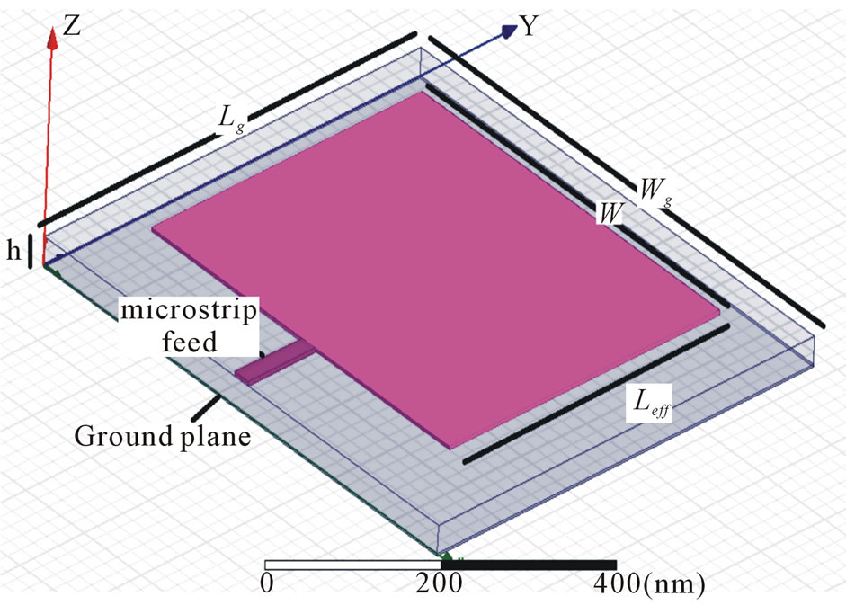
Figure 1. Rectangular microstrip patch antenna.
slots of width, w, and height, h, separated by transmission line of length, l. Thus, it is a non homogeneous structure made up pf two dielectrics i.e. substrate and air. This shows that substrate and air will have different phase velocity and the dominant mode of propagation will be quasi-TEM. Therefore effective permittivity, εeff, comes into consideration. There is fringing effect at the edges of patch, due to which the patch appears to be longer. So, Leff, i.e. effective length is defined which is obtained by adding 2Δl (additional length Δl due to fringing on each end) to the length obtained by using mathematical design equations [10]. Ground plane has length, lg, and width, wg. The tangential components of electric field are in phase. Therefore, maximum radiated field is normal to the surface of the structure. However, normal components of the electric field at the two edges, along the width, are out of phase. Hence, there is no radiation in broadside direction. As per transmission line model ground plane should be infinite in extent. Practically, ground plane is finite with size greater than the patch dimensions by approximately six times the substrate thickness.
The operating frequency range of the designed antenna is 8.55 THz to 10.55 THz with centre frequency 9.55 THz. The substrate is RT Duroid 5870 (εr = 2.33).
Constructional details are shown in Table 1.
Using design parameters RMPA has been designed in Ansoft HFSS as shown in Figure 2.
2.2. Simulation Results
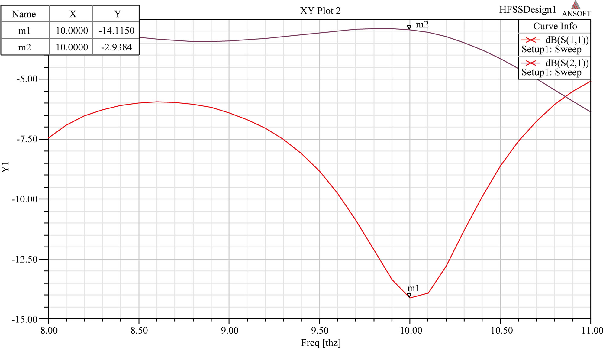
RMPA has been simulated in HFSS. Figure 3 shows the simulation results where S11 is return loss or reflection coefficient and S21 is the gain of the antenna.
Simulation results have been shown in Table 2.
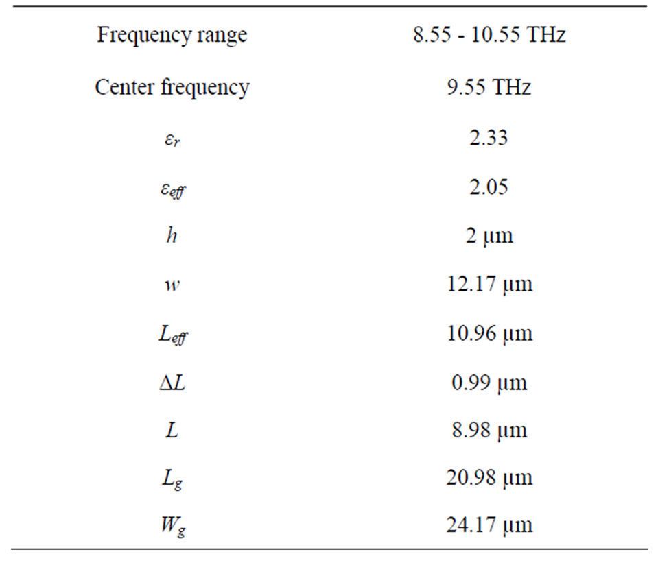
Table 1. Design parameters of RMPA.
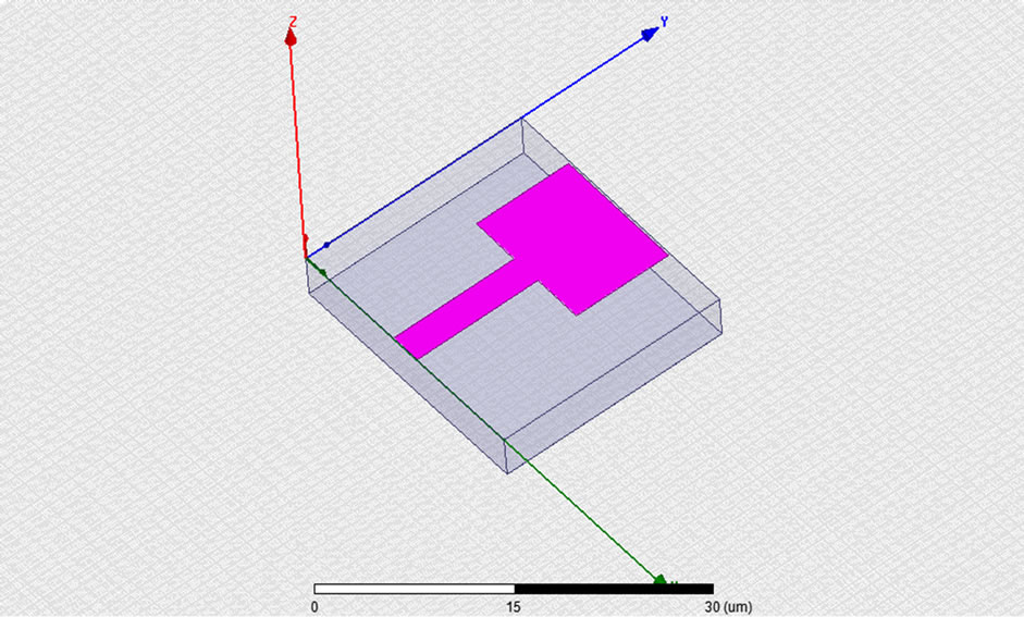
Figure 2. RMPA design in HFSS.
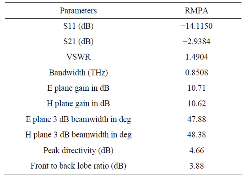
Table 2. Simulation results of RMPA at 9.55 THz.
It can be seen that S11 is crossing 10 dB line and VSWR is less than 2 indicating that less than 10% of the power is reflected. Therefore, 10 dB line is considered as good reference for matching conditions. Bandwidth is 0.8508 THz, which is range of frequencies with VSWR < 2.
3. Proposed 2 Segment Labyrinth MTM
Multiple split ring (2 segment) Labyrinth metamaterial has been proposed having magnetic resonance. It behaves as MNG i.e. Mu Negative Group. Such materials have negative permeability over some frequency region [11,12]. The parameter retrieval i.e. parameter extraction using S parameters [13] has been followed using NRW approach to observe the negative permeability region of SRR MTM. The constructional details along with the curve are as under.
3.1. Constructional Details
It is constructionally very simple, consists of a 2 segment SRR with RT Duroid Substrate [14,15]. It is designed in such a way that the inclusions are much smaller than the operating wavelength. Such structures can be denoted by quasi-static equivalent LC circuit. Unit cell formed in HFSS is shown in Figure 4(a) with constructional details in Figure 4(b) where thickness “t” of the conducting metallic inclusions (N = 2) is 30 nm, height “h” of the substrate is 1.6 nm, conductivity “ρs” is 0.017 × 10⁻⁶ ῼm,
 (a)
(a)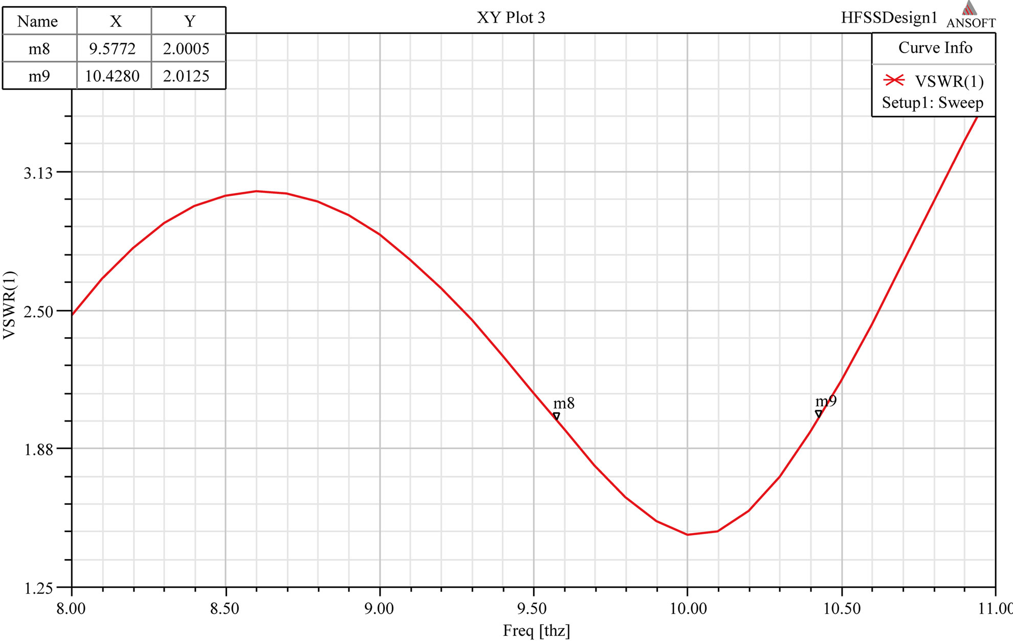 (b)
(b)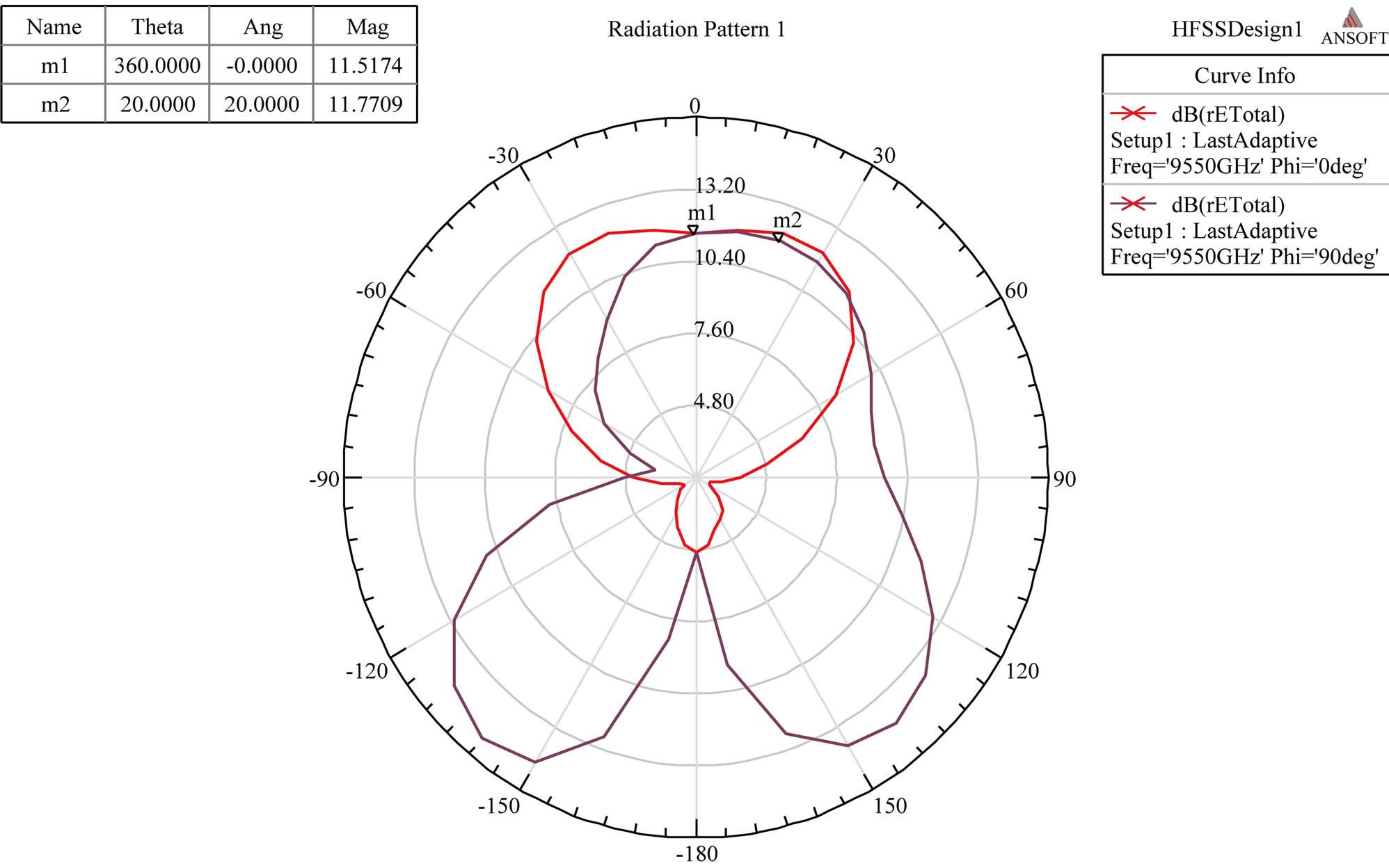 (c)
(c)
Figure 3. (a) Return loss and Gain; (b) VSWR; (c) Radiation pattern in E and H plane of RMPA.
 (a)
(a) (b)
(b)
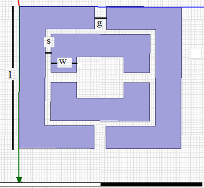
Figure 4. 2 segment Labyrinth SRR MTM (a) unit cell designed in HFSS (b) constructional details with tanϐ = 0.01.
“l” is the side length of the external ring, “u” is the width of the strips, “s” is the separation between two adjacent strips, “g” is the gap width.
3.2. Simulational Results
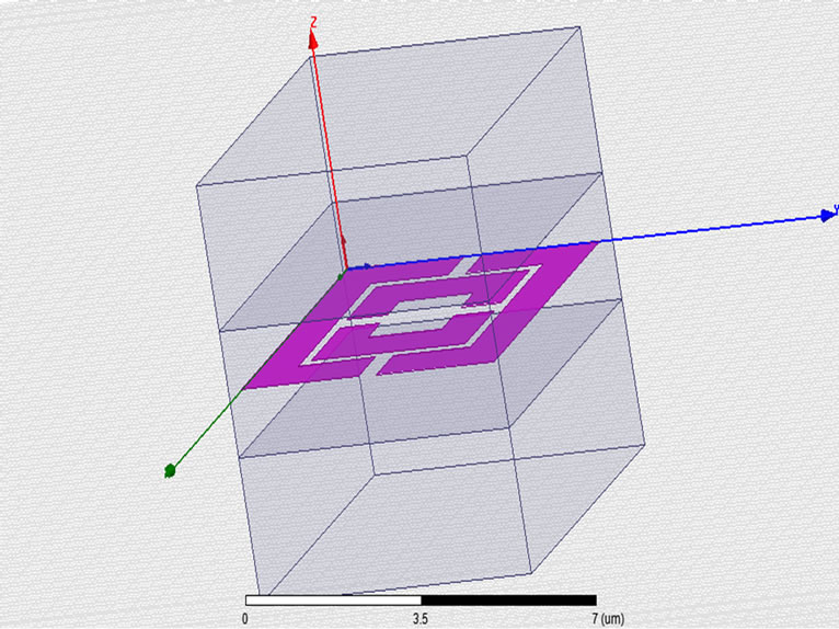
Ansoft HFSS has been used to simulate the unit cell designed in Figure 5(a) having metamaterial in the dielectric substarte bounded by box on either side having air as material and radiation boundary [16]. The boundaries and lumped ports (1 and 2) have been assigned as per Figures 5(b)-(d). Nicolson Ross Wier (NRW) method has been used to calculate the material properties from transmission and reflection coefficients.
It can be observed as in Figure 6 that magnetic resonance is seen at 9.55 THz.
3.3. Mathematical Proof
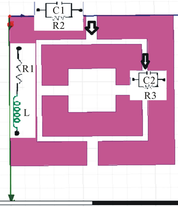
2 segment labyrinth SRR MTM has magnetic properties because of internal inductances and capacitances. It can be simplified in terms of combinations of parallel RC and series RL. Using transmission line theory (quasi-static regime), we can draw its equivalent circuit as in Figures 7(a) and (b).
The L is the inductance per unit length of the loop and C is the equivalent capacitance .This circuit has capacitances from two regions: 1) capacitance from gap “g” in the rings named C1 in parallel with resistance R2; 2) capacitance between the split rings named C2 in parallel
 (a)
(a)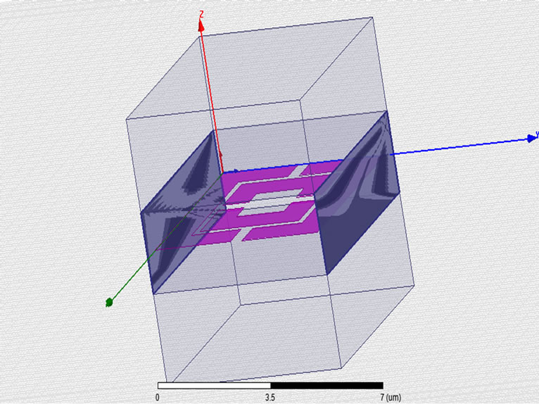 (b)
(b)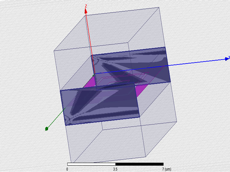 (c)
(c)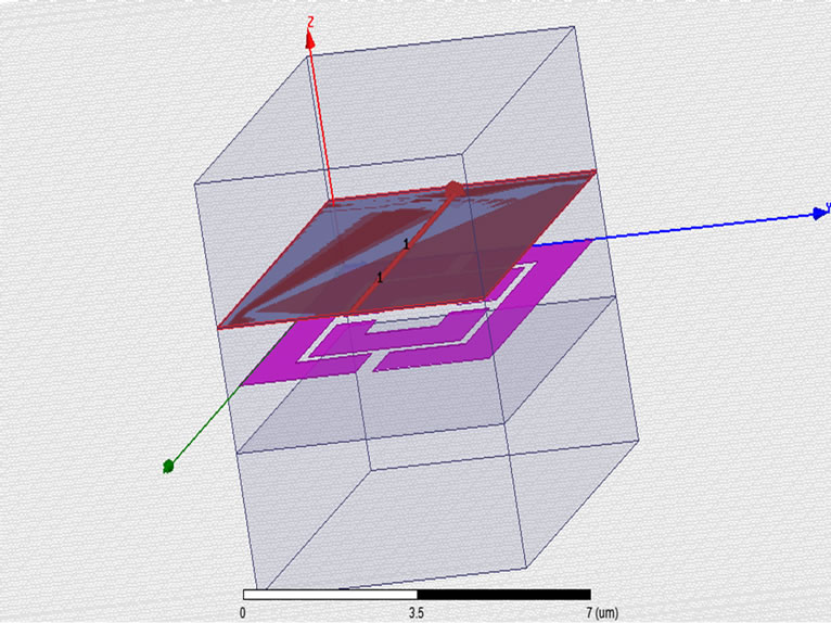 (d)
(d)
Figure 5. (a) Unit cell for simulation; (b) H field; (c) E field specifying boundary condition; (d) Lumped port.

Figure 6. Resonance in permeability at 9.55 THz.
with R3. Also, series resistance R1 is to take into account the losses in the conductor and a shunt resistance R2 and R3 are taken to describe the losses in the dielectric substrate as shown in Figure 7(b). Here, length of the gap plays a significant role and C1 and C2 are of the same order of magnitude.
The expressions for L, C1 and C2 are given by Equations (1), (2) and (3) as below [9]:
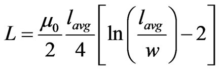 (1)
(1)
where µ0 is the vacuum permeability, lavg is the average strip length calculated over all the rings
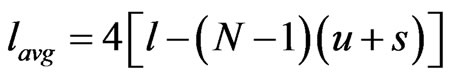 (1.1)
(1.1)
Using 1.1, we get, lavg is 13.8 µm. Therefore, L is 1.58 × 10⁻¹² H.
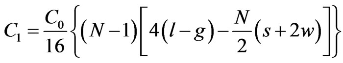 (2)
(2)
“C0” is the per-unit-length capacitance between two parallel strips having width “w” and separation “s” in the presence of a dielectric substrate of height “h” and relative permittivity “ ” and is given by Equation (2.1).
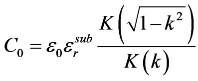 (2.1)
(2.1)
 (a)
(a)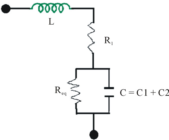 (b)
(b)
Figure 7. (a), (b) Equivalent RLC circuit of 2 segment SRR.
where εo is the vacuum permittivity, “K” is the complete elliptic integral of the first kind,  , and “
 ” is the effective relative permittivity related to the dielectric filling the substrate is given by
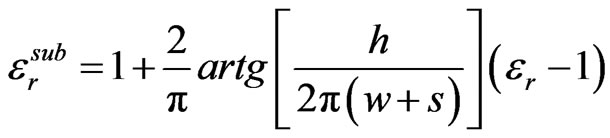 (2.2)
(2.2)
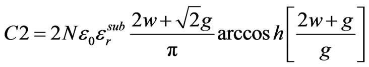 (3)
(3)
Using above expressions we have found out, k = 0.1,  ,
,  ,
,  , C0 = 7.71 × 10⁻¹¹ F. Therefore, C1 is 9.15 × 10⁻¹⁷ F and C2 is 7.62 × 10⁻¹⁷ F. Thus, the resultant Capacitance by virtue of C1 and C2 is the series combination of two. So,
 (4)
(4)
Thus C = 16.77 × 10⁻¹⁷ F.
Resultant impedance of the circuit in Figure 5(b) is given by
 (5)
(5)
where s = jω, and ω = 2πf where “f” is the resonant frequency.
Frequency domain equivalent of Z is given by
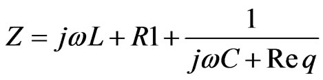 (6)
(6)
At resonance, imaginary part of Z is zero. So,
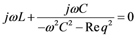
Neglecting Req, we get
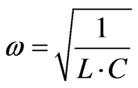 (7)
(7)
On substituting values of L and C we get, resonant frequency as 9.77 THz.
Thus we find around 2% error between the simulational and analytical study of 2 segment labyrinth SRR.
4. Antenna Parameter Optimization
4.1. Design
Antenna is characterized by different parameters e.g. gain, bandwidth, VSWR, 3 dB beamwidth in E, H plane, return loss. These parameters have been obtained for RMPA as in Table 2 using HFSS. Parameter optimization is done by embedding the proposed MTM in the middle of the antenna substrate (εr = 2.33) and just below the rectangular patch such that its center is at [w/2, l/2, h/2] nm as per Table 1 values. Figure 8 shows the position of S-shaped MTM in the substrate.
4.2. Simulation
Simulation results for S-shaped MTM inside RMPA substrate [17] are shown in Figure 9.
Table 3 gives the obtained simulated values of parameters and comparison of 2 segment labyrinth MTM RMPA Vs RMPA without MTM.
5. Conclusion
Upon designing and analyzing proposed MTM inside RMPA substrate, we obtain results as in Table 3. There is around 2% error between numerical simulations and theoretical calculations. It can be seen that there is 4% enhancement in bandwidth with 2 Segment Labyrinth MTM. VSWR improves upto 1.5%. Improvement in S11, i.e. return loss, is upto 5%. However gain (S21) improves
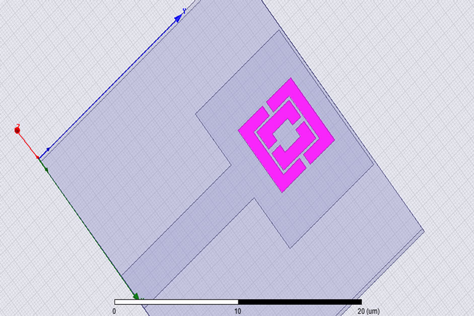
Figure 8. Embedding MTM inside RMPA substrate.
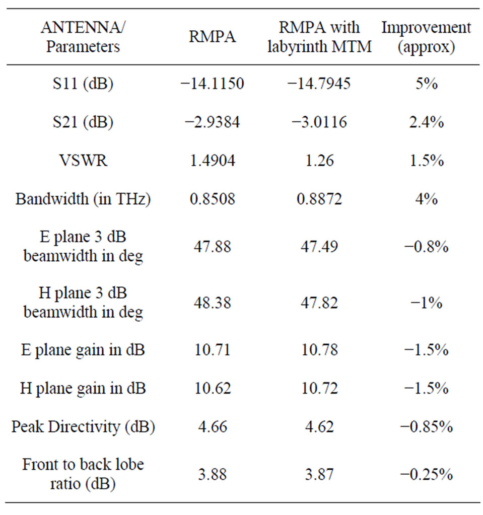
Table 3. Simulation and comparison results of Labyrinth MTM embedded in RMPA substrate.
 (a)
(a)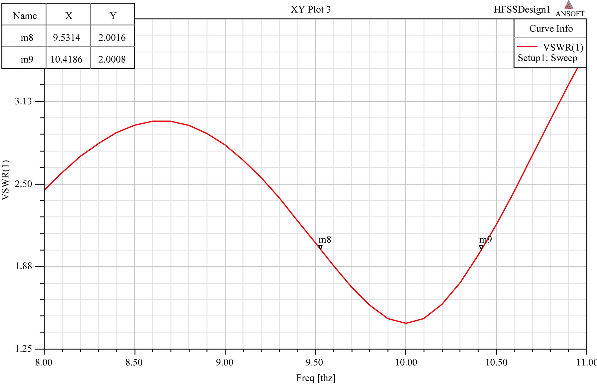 (b)
(b)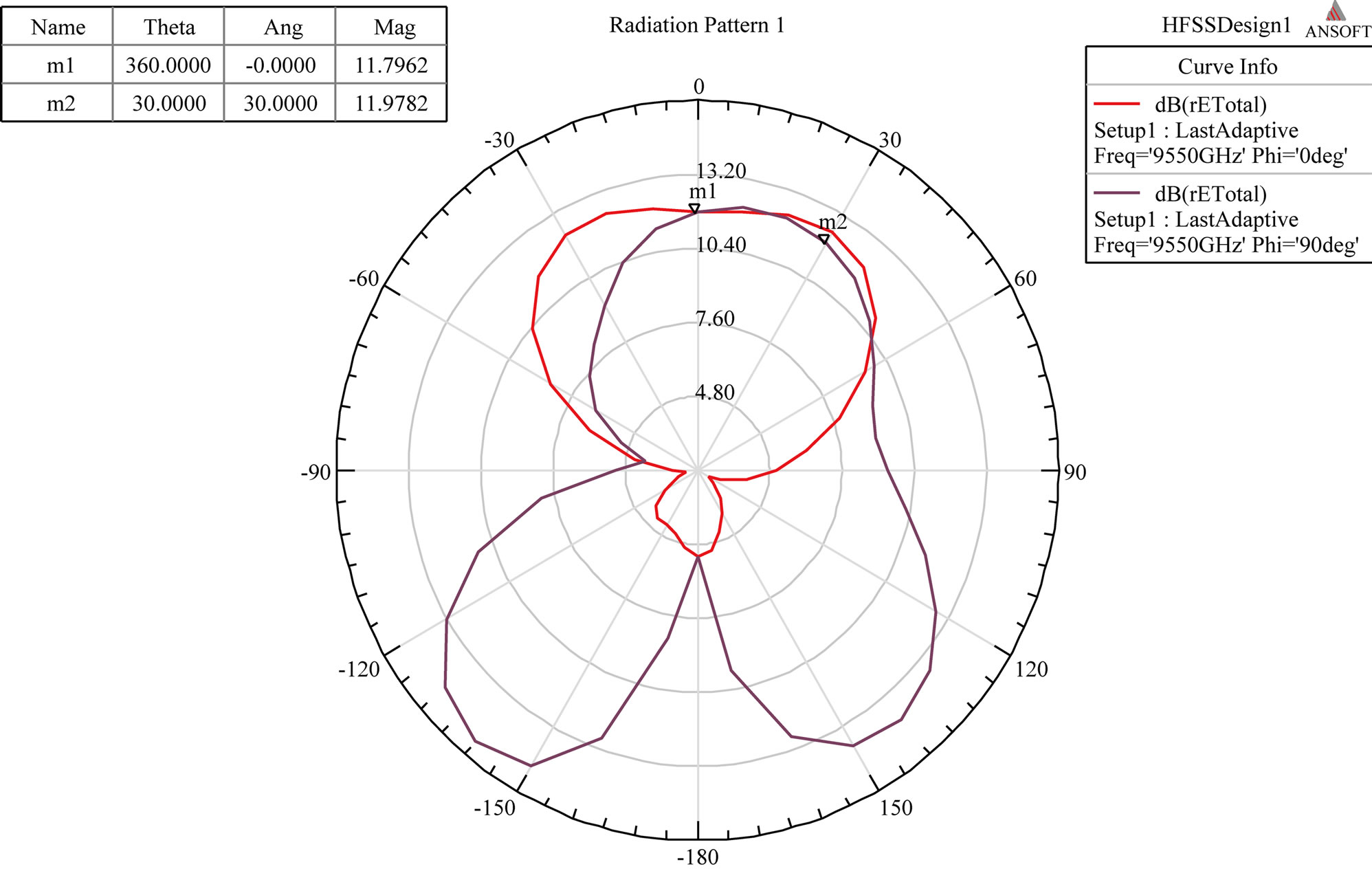 (c)
(c)
Figure 9. (a) Return loss and gain; (b) VSWR; (c) Radiation pattern in E and H plane.
by 2.4%. Trade off lies in improvement of above antenna parameters over directivity, 3 dB beamwidth and majorly front to back lobe ratio.
REFERENCES
- V. G. Veselago, “The Electrodynamics of Substances with Simultaneously Negative Values of ε and μ,” Soviet Physics-Uspekhi, Vol. 10, No. 4, 1968, pp. 509-514. http://dx.doi.org/10.1070/PU1968v010n04ABEH003699
- J. B. Pendry, A. J. Holden, W. J. Stewart and I. Youngs, “Extremely Low Frequency Plasmons in Metallic Micro Structures,” Physical Review Letters, Vol. 76, No. 25, 1996, pp. 4773-4776. http://dx.doi.org/10.1103/PhysRevLett.76.4773
- J. B. Pendry, A. J. Holden, D. J. Robbins and W. J. Stewart, “Magnetism from Conductors and Enhanced Nonlinear Phenomena,” IEEE Transactions on Microwave Theory and Techniques, Vol. 47, No. 11, 1999, pp. 2075- 2084. http://dx.doi.org/10.1109/22.798002
- D. R. Smith, Willie J. Padilla, D. C. Vier, S. C. NematNasser and S. Schultz, “Composite Medium with Simultaneously Negative Permeability and Permittivity,” Physical Review Letters, Vol. 84, No. 18, 2000, pp. 4184- 4187. http://dx.doi.org/10.1103/PhysRevLett.84.4184
- R. A. Shelby, D. R. Smith, S. C. Nemat-Nasser and S. Schultz,” Microwave Transmission through a Two-Dimensional, Isotropic, Left-Handed Metamaterial,” Applied Physics Letters, Vol. 78, No. 4, 2001, pp. 489-491. http://dx.doi.org/10.1063/1.1343489
- E. Ozbay and C. M. Soukoulis, “Observation of Negative Refraction and Negative Phase Velocity in True LeftHanded Metamaterials,” Proceedings of the 36th European Microwave Conference (EuMA), Manchester, 10-15 September 2006, pp. 959-962.
- A. Sihnola, “Character of Surface Plasmons in Layered Spherical Structures,” Progress in Electromagnetics Research, Vol. 62, 2006, pp. 317-331. http://dx.doi.org/10.2528/PIER06042801
- H. O. Moser, B. D. F. Casse, O. Wilhelmi and B. T. Saw, “Terahertz Response of a Microfabricated Rod—SplitRing-Resonator Electromagnetic Metamaterial,” Physical Review Letters, Vol. 94, No. 6, 2005, Article ID: 063901. http://dx.doi.org/10.1103/PhysRevLett.94.063901
- “HFSS Online Help,” Ansoft Corporation, 2007.
- C. A. Balanis, “Antenna Theory,” John Wiley & Sons Inc., Hoboken, 1999.
- W. Withayachumnankul and D. Abbott, “Metamaterials in the Terahertz Regime,” IEEE Photonics Journal, Vol. 1, No. 2, 2009, pp. 99-118. http://dx.doi.org/10.1109/JPHOT.2009.2026288
- H. Benosman and N. B. Hacene, “Design and Simulation of Double ‘S’ Shaped Metamaterial,” IJCSI International Journal of Computer Science Issues, Vol. 9, No. 2, 2012, pp. 534-537.
- R. W. Ziolkowski, “Design, Fabrication and Testing of Double Negative Metamaterials,” IEEE Transactions on Antenna and Propagation, Vol. 51, No. 7, 2003, pp. 1516-1529. http://dx.doi.org/10.1109/TAP.2003.813622
- Y. Minowa, M. Nagai, H. Tao, K, B. Fan, A. C. Strikwerda, X. Zhang, R. D. Averitt and K. Tanaka, “Extremely Thin Metamaterial as Slab Waveguide at Terahertz Frequencies,” IEEE Transactions on Terahertz Science and Technology, Vol. 1, No. 2, 2011, pp. 441-449.
- F. Bilotti, S. Member, A. Toscano, L. Vegni, K. Aydin, K. B. Alici and E. Ozbay,” Equivalent-Circuit Models for the Design of Metamaterials Based on Artificial Magnetic Inclusions,” IEEE Transactions on Microwave Theory and Techniques, Vol. 55, No. 12, 2007, pp. 2865-2873. http://dx.doi.org/10.1109/TMTT.2007.909611
- H.-T. Chen, W. J. Padilla, R. D. Averitt, A. C. Gossard, C. Highstrete, M. Lee, J. F. O’Hara and A. J. Taylor, “Electromagnetic Metamaterials for Terahertz Applications,” Terahertz Science and Technology, Vol. 1, No. 1, 2008, pp. 42-50.
- D. Ionescu and M. Kovaci, “About the Negative Permittivity of Some Metamaterial Composites—Simulational Study,” IEEE 17th International Symposium for Design and Technology in Electronic Packaging (SIITME), Timisoara, 20-23 October 2011, pp. 197-200.