Materials Sciences and Applications
Vol.3 No.6(2012), Article ID:19796,15 pages DOI:10.4236/msa.2012.36049
Evaluation of Corrosion Stability of Water Soluble Epoxy-Ester Primer through Electrochemical Studies
![]()
1Department of Industrial Chemistry, Alagappa University, Karaikudi, India; 2Department of Chemistry, Eritrea Institute of Technology, Asmara, State of Eritrea; 3Kalasalingam University, Virudhunagar, India.
Email: *drrameshmcas@gmail.com, drramesheit@sify.com
Received March 14th, 2012; revised April 22nd, 2012; accepted May 19th, 2012
Keywords: Epoxy-Ester; Water Borne Paint; Polarization and Electrochemical Impedance (EIS) Measurements
ABSTRACT
The corrosion behavior of water borne epoxy-ester primer coatings (10% - 50% PVCs) was evaluated through electrochemical techniques such as polarization and impedance spectroscopic (EIS) measurements. Studies were carried out for a longer duration of exposure extending up to 60 days in aqueous solution of NaCl (5%). Corrosion current (icorr), Corrosion potential (Ecorr), Coating resistance (Rc), Charge transfer resistance (Rct), Coating capacitance (Cc), Double layer capacitance (Cdl), break point frequency (fb), Water uptake (f), diffusion coefficient (Dw) etc., indicated that 10% - 30% PVC coatings performed well in comparison to higher PVCs. Changes in the electrochemical characteristics were found to occur as a function of exposure time in all cases. The corrosion stability of the coatings were found to be greatly affected by the percentage of PVCs. Studies further indicated that when lower concentration of pigments were available, they remained completely surrounded by the binder; Thus leaving no space for the entry of corrosive agents. From these studies, it was concluded that the water borne paints could replace the conventional coatings, containing organic solvents. Therefore, water soluble epoxy-ester primers have to be employed in paints for developing ecofriendly coatings.
1. Introduction
Corrosion is one of the most acute industrial problems. It mostly occurs on metals and its alloys as well as on polymers, woods and ceramics due to materials interactions with water, humid environment, acid rains, industrial emissions, pollutants, chemical by-products and industrial wastes as well as sunlight etc. It usually begins at the surface and decreases the lifespan of materials; as a result materials lose their physical appearance, mechanical and chemical properties. In order to decrease the rate of corrosion and increase the lifespan of materials, several methods are being investigated in recent years [1]. Strict regulations by many countries on the use of volatile organic compounds (VOC) has lead to the development of solvent free coating technologies like powder coating, water borne coatings, electrocoating, UV curable coating systems etc. Among these, in recent years, water borne organic coatings have gained greater importance [2, 3] because of their better performance, availability, ease of application, eco-friendly to environment etc.
The anti-corrosive action of organic coatings to protect a metal substrate from corrosion depends on many factors [4] such as, 1) the quality of the coating, i.e., their chemical and mechanical properties and adhesion to the substrate, water uptake and permeability to water, oxygen and ions etc., 2) the characteristic of the substrate and the surface modification, 3) the properties of the metal/coating interface and their dielectric properties. These offer protection, either by acting as barriers to corrosive agents (O2, water and ions) by suppressing anodic and cathodic reactions or by inserting a high electrical resistance between the anodic and cathodic areas of the corrosion reaction etc. Normally, the conventional organic coatings act as physical barrier against aggressive agents (such as O2 and H2O). However, they are not very effective as impenetrable coatings and corrosive agents reach the substrate due to some defects in the film. In order to improve their corrosion protection properties, pigments can be added to coating materials, which may protect the metals through physico-chemical (barrier mechanism), electrochemical or ion exchange mechanisms [5].
In recent years, several studies have been conducted to evaluate the protection ability of coatings through physical, chemical and electrochemical methods. Among these, electrochemical analysis of coatings have been found to be more advantageous results can be achieved in a very short period of exposure [6-10]. Generally, electrochemical methods are employed to identify the degradation of coated metal substrates after penetration of water at the coating-substrate interface, osmotic blistering, cathodic and anodic delamination etc. [11]. The corrosion of coated metals is an electrochemical process; therefore we employed the electrochemical methods to evaluate the corrosion performance of coatings over a metal substrate exposed to aggressive medium [10]. In the present studies, corrosion stability of water borne epoxy-ester primer was evaluated through many recent techniques employed in evaluating the corrosion stability of coatings. Electrochemical techniques such as polarization and AC electrochemical impedance (EIS) measurements were employed. In addition to impedance measurements, polarization measurements were also used to evaluate the coatings through their corrosion current and corrosion potential with respective tafel plots. Even though the Tafel polarization method may not be very useful in highly resistive coatings, still it can be employed as a quantitative method to evaluate the coating performance. Among the electrochemical techniques, the EIS has proved to be an effective tool to evaluate the coating parameters and also to identify the better quality primers [12,13].
2. Experimental Details
2.1. Materials and Method of Preparation of Vehicle
Synthesis of epoxy-ester (EER) resin: Synthesis of epoxy-ester was done described earlier [14]. In brief, a 500 ml three-necked round bottom flask equipped with reflux condenser, stirrer, sample charging portion with thermometer pocket was used. In the synthesis of resin, solid epoxy resin was dissolved in MIBK and charged in the flask, which was heated and stirred to facilitate the dissolution of epoxy resin. Temperature was adjusted to 110˚C. Pyromellitic dianhydride (PMDA) as curing agent was added gradually over a period of half an hour to epoxy resin solution. The esterification was carried out for obtaining a product with a desired epoxy equivalent and acid value. The acid value and epoxide equivalent of PMDA reacted product was determined following ASTM [15]. When the desired polymerization stage was achieved (i.e., epoxide value reached to 80), half of butyl cellosolve (co-solvent) was added and MIBK was removed using a Dean and Stark assembly as azeotropic distillation process [16]. The sample was cooled to 80˚C and neutralized with NH3, followed by the addition of deionized water with constant stirring to obtain required solid content of aqueous dispersion of pyromellitic dianhydride cured epoxy resin.
2.2. Composition of Epoxy-Ester Paint (EEPS) Method of Preparation
Synthesized epoxy-ester [14] was used for formulating the water-soluble epoxy paint with 40% volume solids. Pigments were premixed and added to epoxy-ester slowly in an attritor. The attritor was run till the Hegmann gauge value of 5 is reached. Various pigment volume concentrations (ranged between 10% - 50%) were prepared by taking required quantity of pigments, binder and solvents. The paint was then transferred to an airtight container. For washing the attritor a mixture of methyl isobutyl ketone (MIBK), cellosolve and water was used as solvent. A typical formulation for 10% PVC of net weight of 500 gm of epoxy-ester paint (40% volume solid) was as follows:
Red iron oxide = 50.00 g Zinc phosphate = 10.00 g Talc = 20.00 g Resin (30%) = 406.00 g Water-butyl cellosolve mixture (4:1) = 14.00 g The viscosity of the paint was adjusted with solvents and then paint was applied using brush on cleaned mild steel substrates. The paint was then allowed to cure for about half an hour in hot air oven at 180˚C, and thereafter, it was kept under ambient conditions for one-day before subjecting to various tests. The thickness of the films was kept at approximately (40 ± 5) mm, which was used as the working electrode for the electrochemical measurements.
2.3. Electrochemical Evaluation of the Coatings
Three cylindrical glass tubes (each of 5 cm length and 1 cm dia.) were fixed on the coated flat surfaces with the aid of epoxy adhesives to obtain a good adhesion to the flat metallic coated substrate, which created a specially arranged cell set up (Figure 1). The electrolyte (5% NaCl) was filled in the tube up to 3.5 cm height. The exposed area of the coated substrates was kept at 1 cm2 [17,18]. The coated metallic electrodes were then evaluated through the Tafel polarization and impedance spectroscopic methods under atmospheric conditions.
2.3.1. Tafel Polarization Measurement
Polarization measurements of coated materials were carried out at three hours interval up to 24 hours. A glass tube was filled with aqueous solution of NaCl (5%) to which a platinum foil and a saturated calomel electrode were placed to act as counter and reference electrodes. The painted panels of 1 cm2 were exposed to NaCl (5%) which acted as working electrode. (See Figure 1 for schematic diagram of the experimental cell assembly).
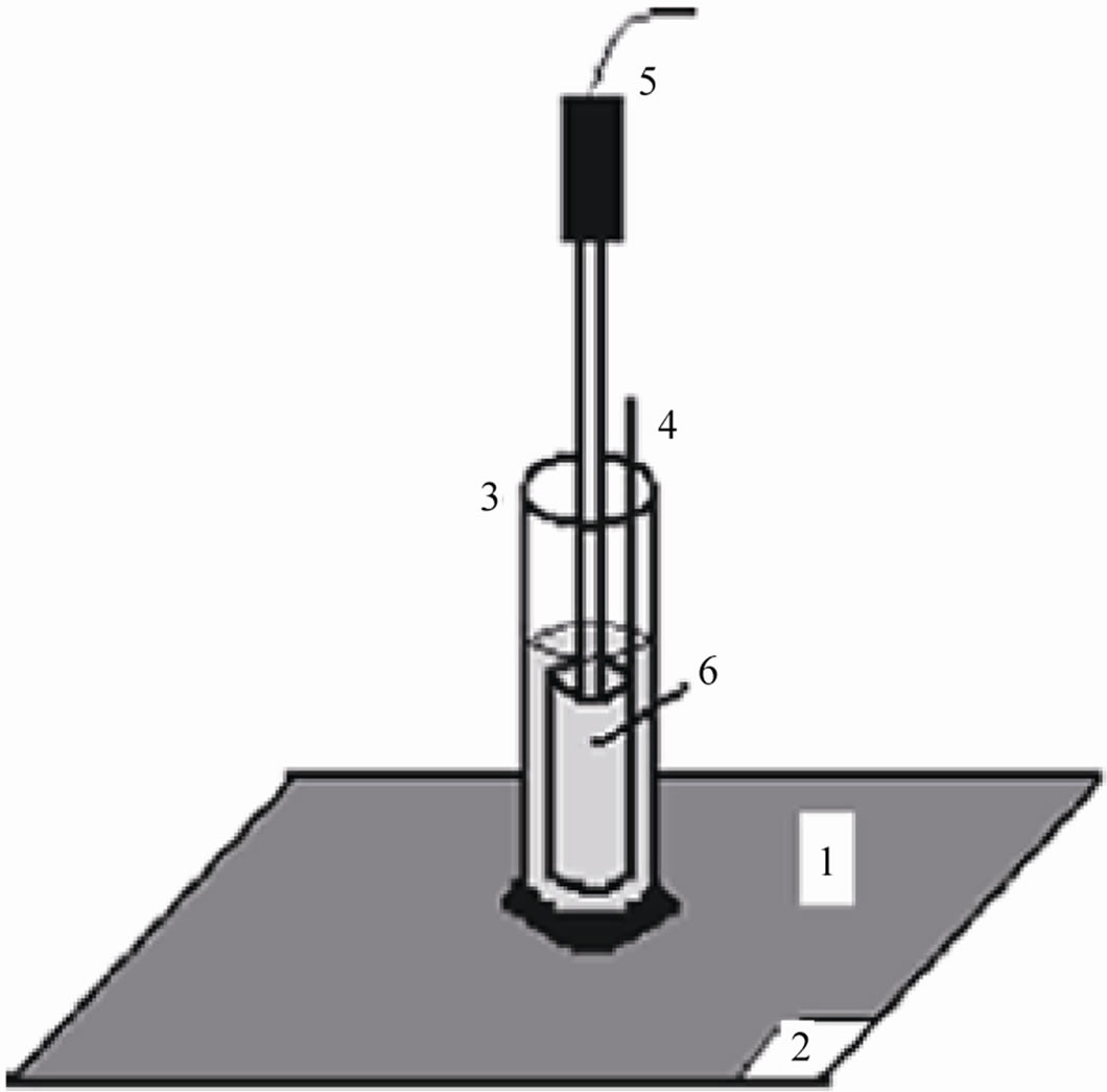
Figure 1. Experimental cell setup: 1) painted steel panel, 2) paint removed area for making working electrode contact, 3) glass tube, 4) platinum counter electrode, 5) SCE reference electrode, and 6) test electrolyte.
The assembly was connected to BAS 100 A Bio-electrochemical analyzer. A time interval of 15 minutes was kept for each experiment to obtain a constant open circuit potential (OCP). The changes in potential were recorded until its stabilization at a value referred to as the corrosion potential (Ecorr) was reached. The coated substrates were polarized at 300 mV anodically and 200 mV cathodically with respect to OCP of the system at a sweep rate of 1 mV/sec. Log current vs potential plots were recorded. The corrosion current (icorr) and corrosion potential (Ecorr) were calculated from their respective Tafel plots. The corrosion rate of coatings was calculated from their respective corrosion current densities following Gonzalez et al. [9] as follows:
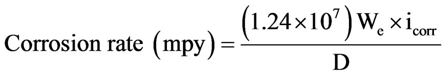
whereWe—Electrochemical equivalent (mg/columb)
icorr—Corrosion current density (A/cm2)
D—Density (g/cm3).
2.3.2. EIS Measurement
The electrochemical cell set up was similar to that used in the Tafel polarization measurement. EIS measurement was performed by using an EG & G Princeton Applied Research (PAR) model 6310 Potentiostat/Galvanostat lock-in amplifier with Equivcurt 398 software [19,20].
The impedance measurements were carried out over a frequency range of 100 KHz to 10 mHz at 10 mV AC amplitude sinusoidal voltage was super imposed over the steady state potential. From the impedance plots, coating resistance was obtained from the lower frequency end of the corresponding Bode /Z/ plots (impedance vs frequency). Coating capacitances (Cc) were estimated from the extrapolation of the linear portion of Bode-amplitude graphs.
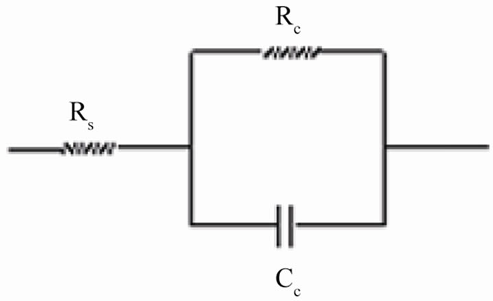
The coating resistance (Rc) and the coating capacitance values were calculated using the equivalent circuit consisting of solution resistance (Rs), coating resistance (Rc) and constant phase element (Figure 2(a)). For the description of a frequency independent phase shift between an applied ac potential and its current response, a constant phase element (CPE) was used which is defined in impedance representation as:
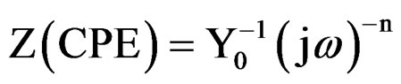
where Y0 is the CPE constant, w is the angular frequency (in rad·s–1), j2 = –1 is the imaginary number and n is the CPE component. Depending on n, CPE can represent resistance (Z(CPE) = R, n = 0), capacitance (Z(CPE) = C, n = 1), inductance (Z(CPE) = L, n = –1) or Warburg impedance (n = 0.5) [21]. For converting Y0 in to Cc [22], following equation was used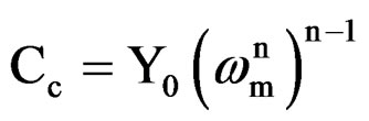
where, Cc is the coating capacitance and  is the angular frequency at which wn is maximum. The impedance data were also analyzed using equivalent circuit given in Figure 2(b). Where Rt is the charge transfer resistance and Cdl as the constant phase element for the double layer capacitance. Experiments were carried out up to a maximum period of 60 days and the corrosion ability of each
 (a)
(a)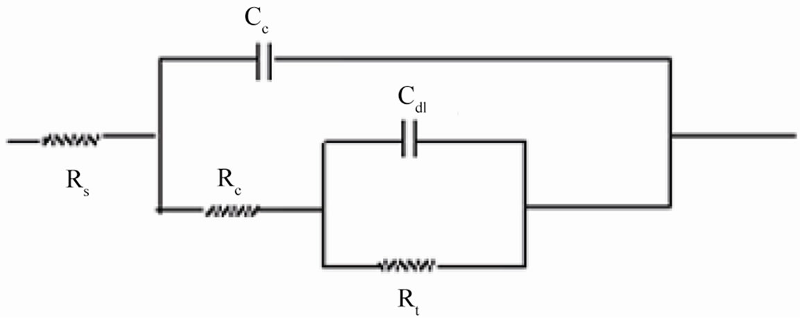 (b)
(b)
Figure 2. (a) Equivalent circuit for painted steel panel; (b) Equivalent circuit for defected coated steel.
primer coating was used to apply suitable electrochemical circuits (Figure 2(a) or Figure 2(b)).
3. Results and Discussion
3.1. Tafel Polarization Measurement
The potentiodynamic polarization of pigmented epoxyester coated substrates was carried out in aqueous solution of NaCl (5%) and the results are shown in Table 1. Corrosion potential (Ecorr) of uncoated and coated specimens was shifted towards negative direction with the passage of time; however, in coated specimens the shift was a little less in the negative direction (Table 1) indicating the cathodic control of the corrosion process. Further, during the study period of 24 hrs, an increase in corrosion current implies that the corrosion process was active with oxygen reduction as the rate-controlling step [23]. The high values of negative shift of corrosion potential with increase in exposure duration for all coatings indicated high susceptibility of steel surface to corrosion [24]. These observations indicated that, corrosion process is directly related to the diffusion of water, ions and oxygen from the polymer matrix/environment. This may be related both to the chemical composition of the matrix as well as to the presence of pores, voids or other defects in the coatings [25]. With increase in the PVC (between 10% - 50%) of the formulation, a negative shift of the corrosion potential with increased corrosion current was
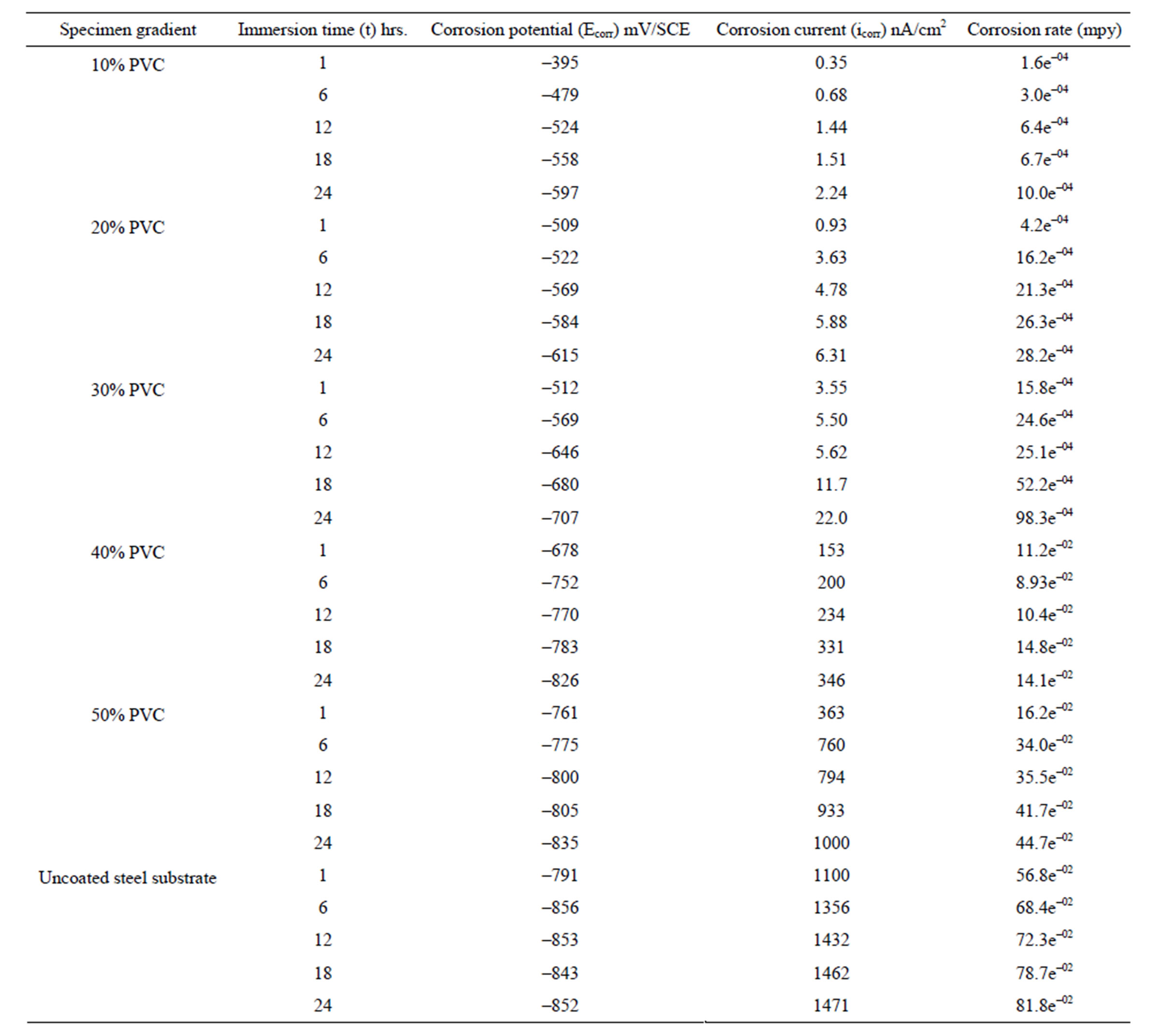
Table 1. Potentiodynamic polarization results of water-based EEPS of various PVC’s/uncoated steel substrates in 5% NaCl medium.
observed.
Normally, with lesser amount of pigments, the pigment particles remains completely surrounded by the vehicle or binder, however, when the amount of pigment is increased a situation arises when enough binder is not available to fill the voids between the pigment particles and the binder [26]. It was clear from these results that low PVC formulation possesses the best corrosion resistant property. Comparing the polarization results of higher PVC formulations and uncoated specimens one can observe the anodic nature of the coatings. These results are similar to there reported by other workers [27]. Further, it was also observed that, when the polarization is carried out beyond 24 hrs a positive shift of corrosion potential and significant fall in corrosion current was observed. This may be attributed to the protective nature of the corrosion products that were formed, which perhaps kept the metal in the passive state. A similar observation was also reported with acrylic electrodeposited coatings exposed to a detergent solution of pH 11 [28].
3.2. EIS Measurement
Electrochemical impedance spectroscopy method is a powerful tool to study the performance of high resistance paint coatings and has been extensively used to measure the corrosion protection properties of organic coatings on metal surfaces [29-33]. Bode impedance plots for epoxy ester based primers of 10% - 50% PVC formulations applied on steel surface immersed in aqueous solution of NaCl (5%) for different exposure durations are shown in Figures 3-6. The responses of impedance magnitude and phase shift varied with the exposure duration indicating the decaying nature of the coats under a specific corrosive environment. Normally, metals protected with organic coatings behave like multiphase heterogeneous systems [34]. Water, ions and oxygen penetrates through the defective coating and reach the metal/paint interface leading to the initiation of the corrosion processes. The equivalent circuits in the case of coatings with very high barrier effect and defective coatings are shown in Figures 2(a) and (b) respectively [35].
Normally for intact coatings Rc is high, which is typically ³108 W·cm2 [36,37]. The incorporation of water to polymeric film in due course results in enhanced conductivity and switchover from capacitive behavior to a mixed control i.e., capacitive at high frequencies and resistive at low frequencies. In some cases decrease in /Z/ at low frequencies was not continuous but some recovery was possible with the coated panels showing a renewed capacitive effect. This may be attributed to the specific role of the pigments. Further, the thickness of the coatings seems to have an influence on diffusion process for the aggressive species such as water and chloride ions. The low frequency (LF) part of the diagram shows the behavior of metal-coat interface in terms of either corrosive or anticorrosive property.
A decrease in impedance on the LF side with increase in time of exposure in all the formulations (shown in Fig-
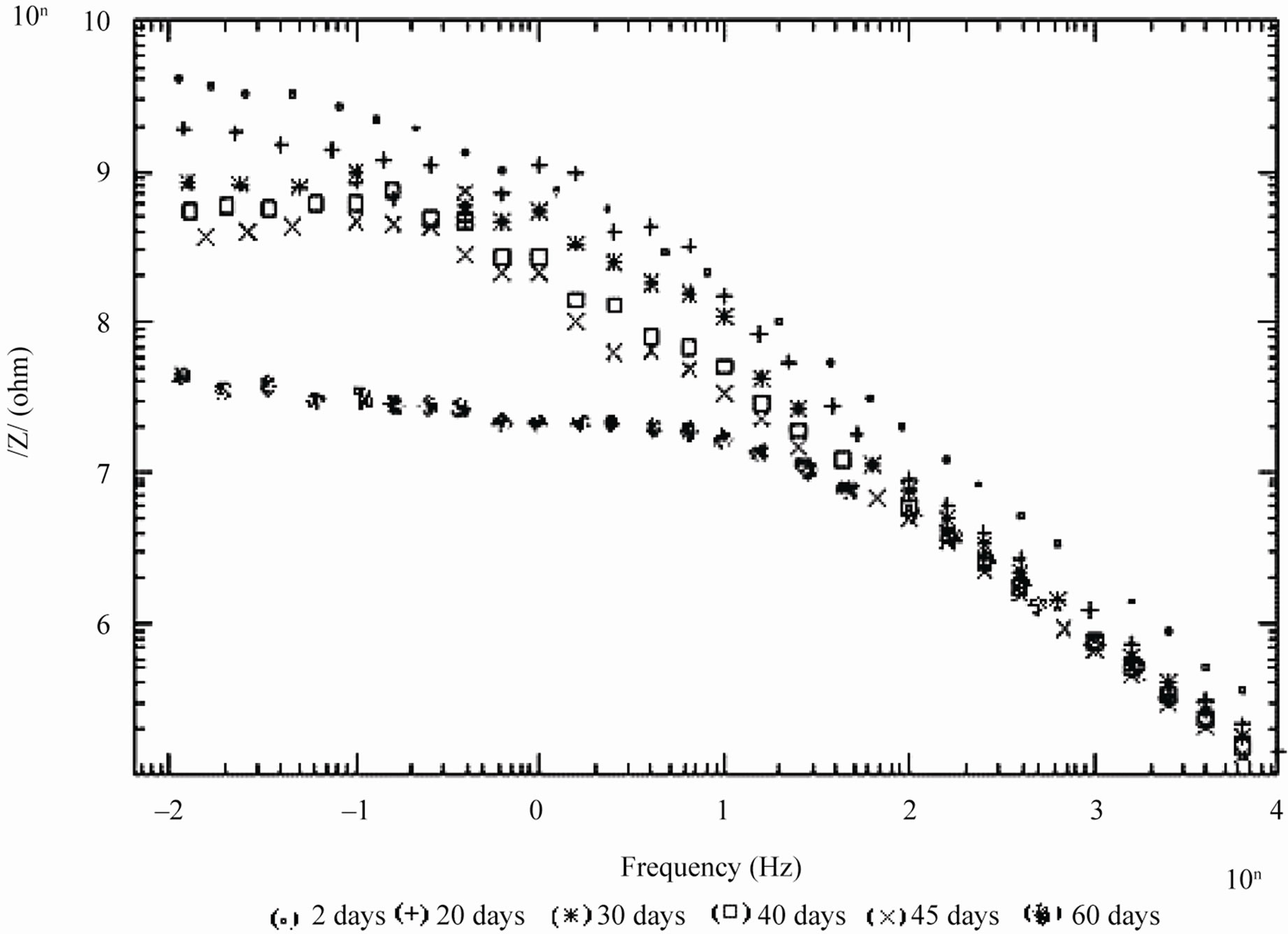
Figure 3. Bode /Z/ plots of 10% PVC EEPS coated substrate exposed at different time intervals in 5% NaCl.
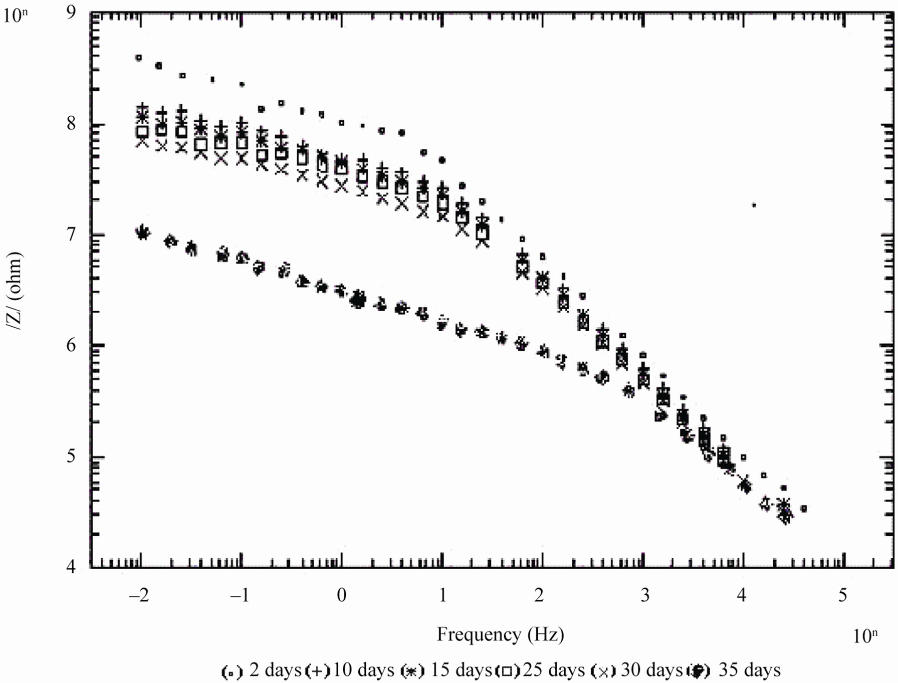
Figure 4. Bode /Z/ plots of 20% PVC EEPS coated substrate exposed at different time intervals in 5% NaCl.
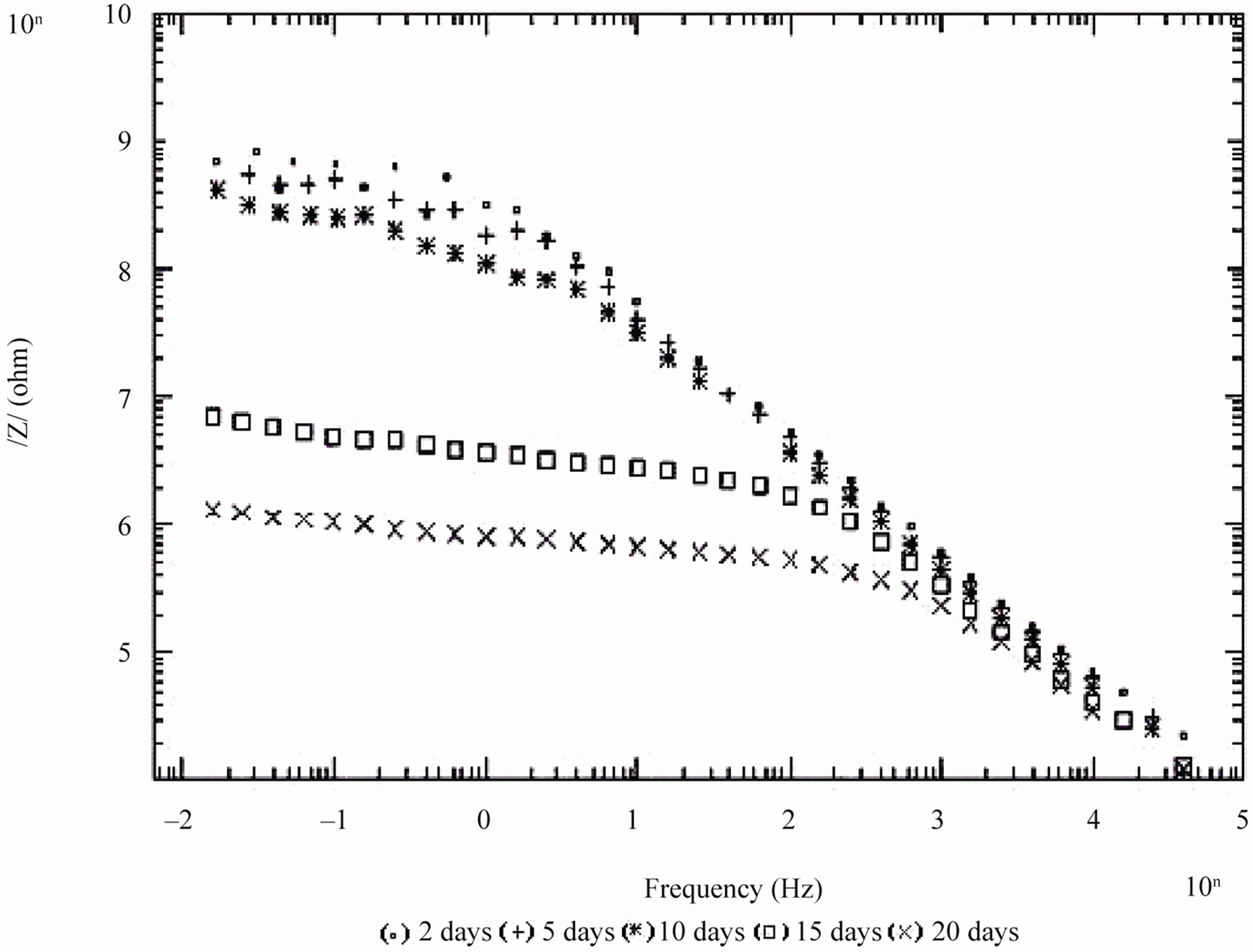
Figure 5. Bode /Z/ plot of 30% PVC EEPS coated substrate exposed at different time intervals in 5% NaCl.
ures 3-6) indicates the absence of reaction process, which impedes corrosion. While in the high frequency part of the Bode /Z/ plot no such remarkable differences in impedance behavior was observed.
In case of 10% PVC formulation, even after 60 days of exposure coating impedance remained at >107 Wcm2 suggesting an excellent performance. Impressive performance was also observed with 20% PVC for up to 35
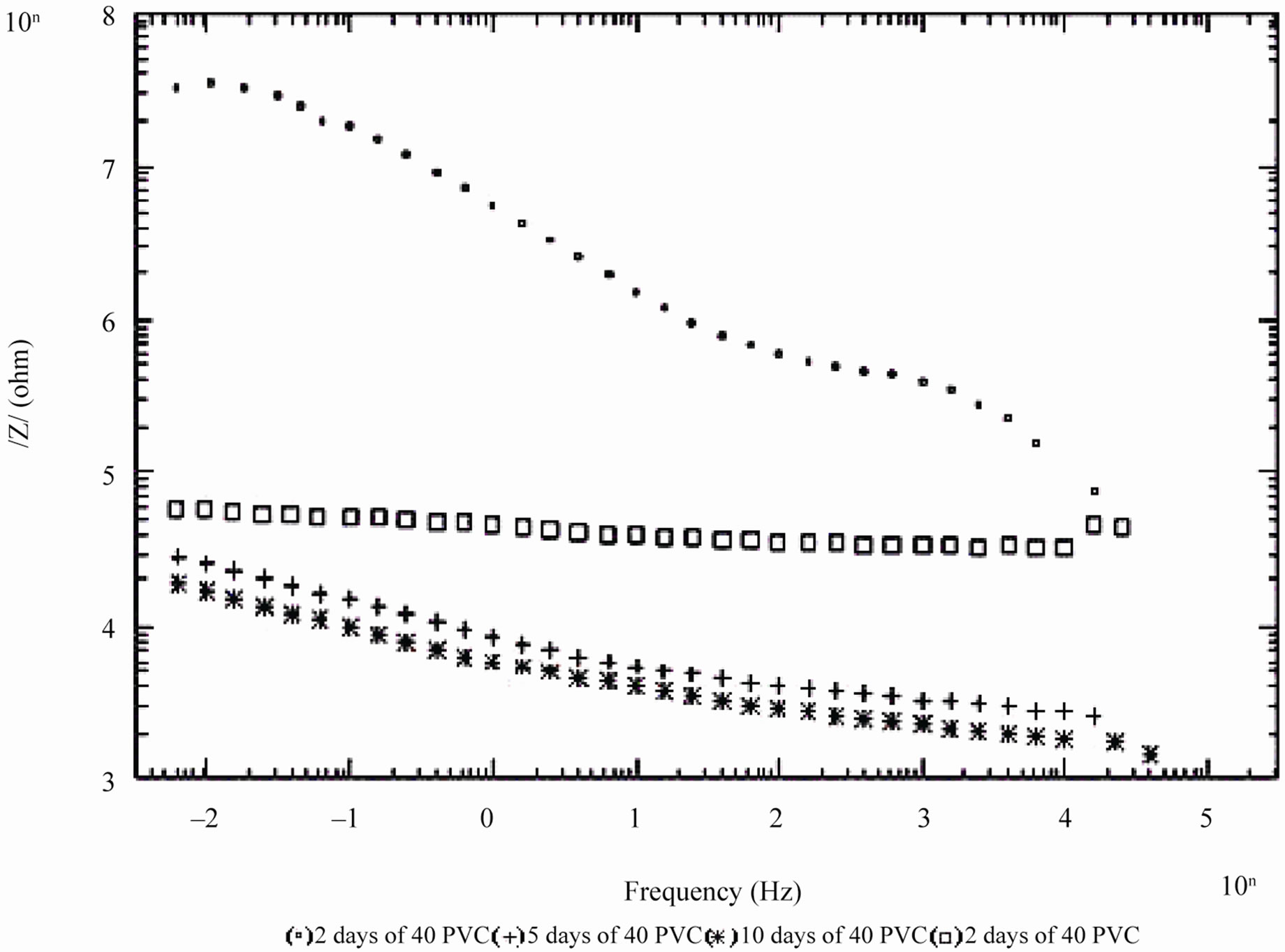
Figure 6. Bode /Z/ plot of 40% and 50% PVC EEPS coated substrate exposed at different time intervals in 5% NaCl.
days and with 30% PVC good performance only up to 20 days of exposure was observed to corrosive medium. Because of the poor performance at 40% and 50% PVC data was merged and shown only for the minimum days (Figure 6). For 10% - 30% PVC coatings, middle frequency range of spectra contained only one capacitive contribution (Figures 3-5) shown in linear form of the logarithm of electrode impedance, log/Z/ against log f with a slope very close to –1 [38]. Resistance of low PVC (10%) coatings was higher than 20% and 30% PVC coatings. It is perhaps due to low conductivity, diffusion of ions from the aqueous solution of NaCl (5%) did not occur.
During shorter period of exposure, the slope of impedance against logf was about –1 and the phase angle was almost –90˚ [39], indicating high impedance of the coatings (see Figure 7). With 40% and 50% PVC formulation (curve d and e in Figure 7) horizontal part of all frequencies correspond to low phase angle indicating the corrosive state of the substrates. With lower formulations (10% - 30% PVC), the rise in phase angle may suggest the capacitive behavior of coatings. Figure 7 is also useful for measurement of breakpoint frequency (fb), which evaluates the capacitive-resistive transition behavior of the coatings. According to Haruyama et al. [40] high frequency breakpoint (fHF) is proportional to the delaminated area (Ad). However, Hack and Scully [41] have broadened the breakpoint method with certain assumptions showing a relationship between the low frequency breakpoint (fLF) and the defected area (A). It is impossible to measure correctly the value of high frequency f45 using the breakpoint method if the ratio of Ad/A was lower than 5 × 10⁻⁴ [42].
In the present studies fb was calculated as low frequency breakpoint (fLF). Because of the high resistance of the coatings, the depression of the phase angle curve at high frequencies was above 45º particularly during the initial periods of exposure when the delaminated area was minimum. Further, the defective area percentage was almost <0.001%. According to Hack and Scully [41] when the defective area percentage of coatings was < 0.001%, the depression of the phase angles does not occur in high frequency domain. The variation in breakpoint frequency during the exposure duration for formulations of 10% - 30% PVC coatings exhibited complete resistive behavior over all other frequency ranges where the phase angle was below 45˚ [43].
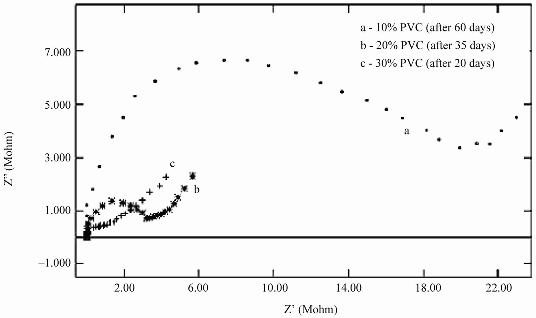
The low values of fb for 10% PVC suggests best performance, followed by that of 20% and 30% PVC’s. The shift of fb to higher values with increased exposure duration was interpreted as an increase due to the delaminated area or on the thickness of the coated film [44]. For all the coatings, except 50% PVC no depression in the imaginary part of the impedance (Z”) at all the frequencies during the initial period of exposures was observed suggesting high capacitive nature of the film (Figures 9(a) and (b)). Only during longer exposure duration a depression in Z” was observed, which is in semicircular plots
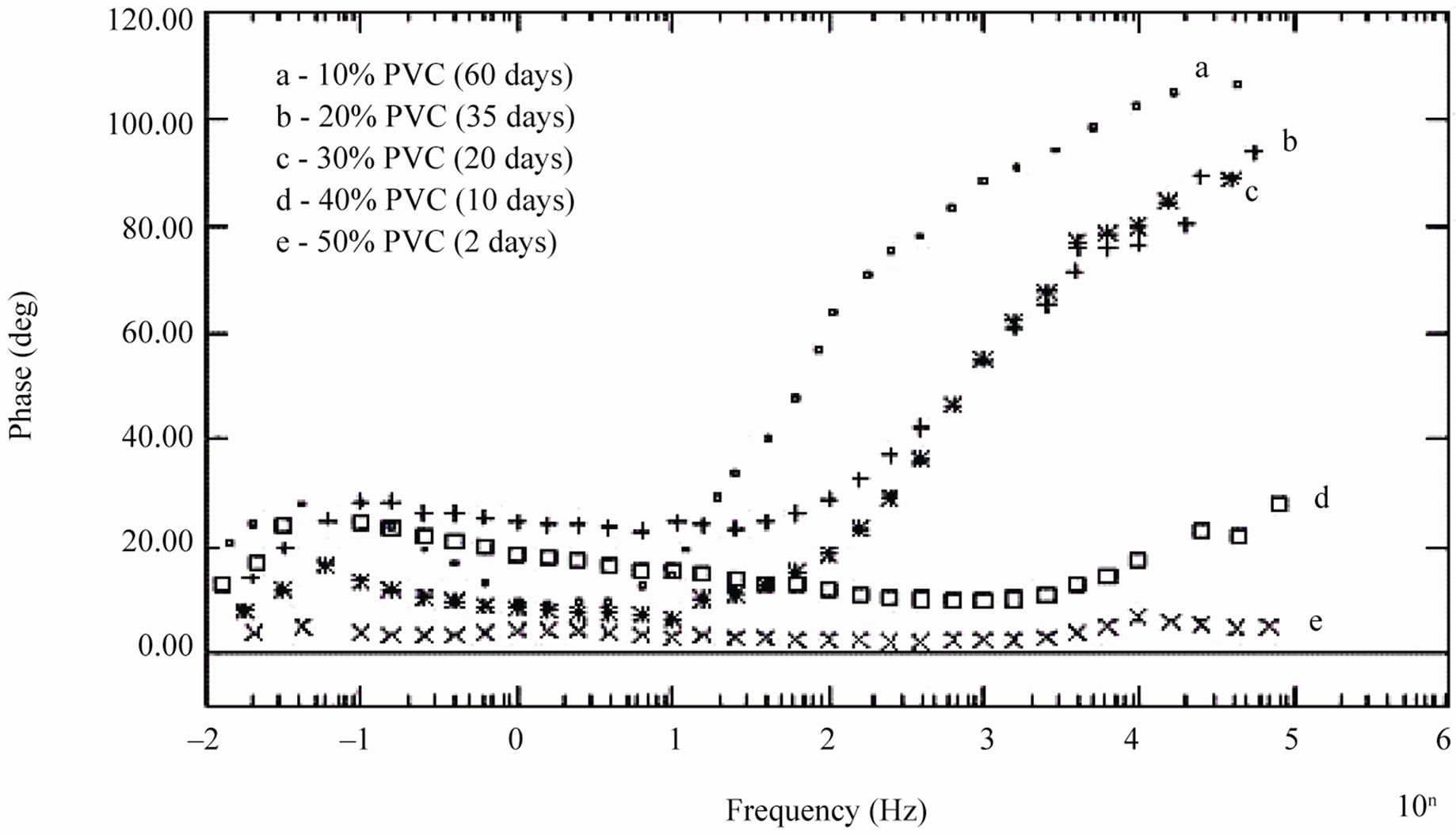
Figure 7. Bode phase diagram of different PVC EEPS coated substrates at their limit of exposure times.
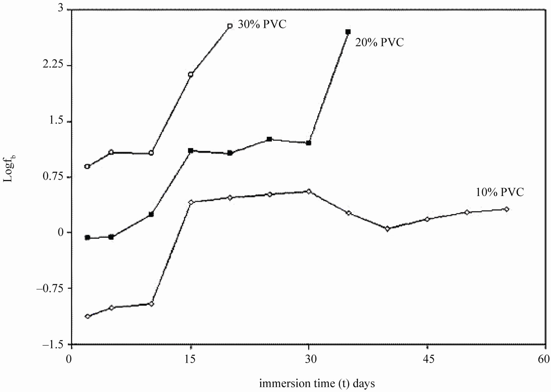
Figure 8. Breakpoint frequencies of EEPS coated on mild steels immersed in 5% NaCl solution.
indicated the onset of the corrosion process at the coating-metal interface [28]. The diffusion controlled corrosion process was determined from the rising portion of the curve at low frequency tail end.
The coatings had very high resistance during the initial period of exposure and almost similar as seen at the beginning of exposure duration when coatings generally acted as intact layer. The electrical equivalent circuit (EEC) of intact coatings (shown in Figure 2(a)) is generally represented by a series of connections of solution resistance (Rs) and coating capacitance (Cc). It must be noted that the capacitance is often substituted by a constant phase element (CPE) in order to take into account the divergence from the pure capacitive behavior.
When an ionic path was created in the coatings, a depressed semicircle was observed in the Nyquist plot when the coated materials were exposed to the aqueous solution of NaCl (5%) for a longer duration. This type of impedance (Z”) can be represented by an EEC including the solution resistance (Rs) in series with a parallel com-
 (a)
(a)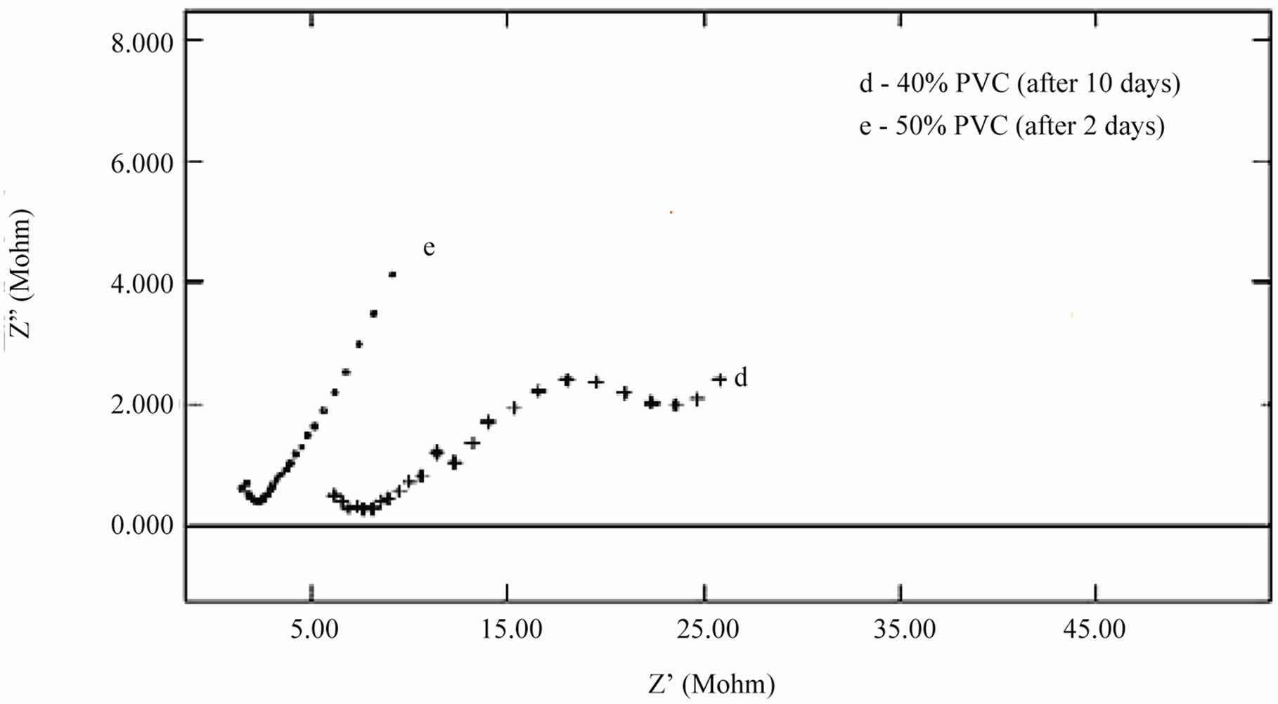 (b)
(b)
Figure 9. (a) & (b) Nyquist plots of different PVC EEPS coated substrates at their limit of exposure time.
bination of coating capacitance (Cc) and the coating resistance (Rc), which is related to the ionic conduction through the coatings. Inspection of the EIS spectra (Nyquist) of higher PVC coatings revealed a two-time constant in most of the cases, most probably this may be due to the higher frequencies of PVC of coatings and possibly it may be an artifact of the voltage clamp (Figure 9(b)).
The impedance parameters were obtained from respective Bode /Z/ plots and are shown in Table 2. The Rt and Cdl are the two parameters which are normally used to specify the disbanding of the coatings and the onset of corrosion at the interface. These parameters decrease the charge transfer resistance and increase the capacitances during the first few days, indicating the entry of electrolyte into the epoxy coating [45,46]. According to Fick’s Law [47] this may the first step of electrolyte penetration through the micropores of an organic coating and was related to water uptake. Thereafter, during the initial period of exposure values of Rt, Cc and Cdl reached a plateau and remained constant over a longer duration. This behavior perhaps also confirms the hypothesis of the existence of passive film on the steel surface, which perhaps prevents corrosion process at the substrate, indicating good corrosion protective properties of lower PVC coatings. This may be taken as the second step in electrolyte penetration through the macro pores of the coating, which may become deeper and deeper with the pas-
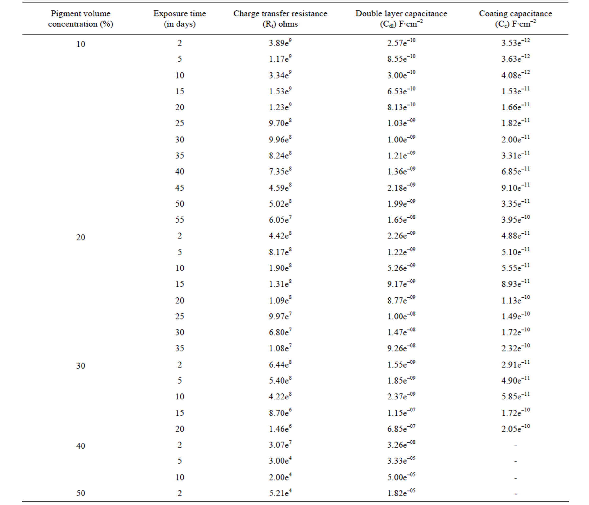
Table 2. The electrochemical impedance results of water-based EEPS coated substrates in 5% NaCl medium at 100 kHz - 10 mHz [Bode Z plot].
sage of time until the aggressive materials pass through the epoxy coating and reach the metal surface. This leads to the beginning of electrochemical process on the metallic interface as a consequence of the loss of coating. Higher values of Rt and lower values of Cc and Cdl for the epoxy coatings with 10% and 20% PVC’s indicated greater corrosion stability due to the existence of passive anodic oxide layer [48,49].
The Cdl is a measure of an area from which the coatings have been disbanded and can be measured only at a very advanced stage of deterioration. The change in Cdl values may depend either on disbanding of the coatings or on the accumulation of corrosion products during the corrosion processes [50]. The best performance with 10% PVC and the impressive performance of 20% PVC were established from the constant values of Cdl during the long period of exposure (35 - 60 days).
Results of impedance values showed fluctuations in the resistance and capacitance values during the period of exposure (Table 2). According to Yin et al. [44], fluctuations in these values were found to be associated with the instability of the accumulated corrosion products on the metal-coating interface. Variations in capacitance with immersion time could be 15% of plasticization effect and rest 85% coalescence induced with water uptake especially in water borne coatings [51].
The penetration of Na+ and Cl– ions in the coatings can also influence the capacitance [52]. The relationship between the capacitance and the dielectric constant (relative permittivity, er) was calculated according to the following equation:
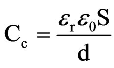
wheree0 is the vacuum dielectric constant (8.85 × 10⁻¹⁴ F·cm–1);
S is the surface Area;
d is the coating thickness.
The water uptake causes an increase in the relative dielectric constant values [53]. In the present studies, relative permittivity values were around 10 indicating low water content in 10% - 30% PVC coatings on steel surface (low porosity), revealing better corrosion stability compared with higher PVC coatings [54]. Reduction in barrier effect of primers can be evaluated through the measurement of the volume of the water that enters and the rate at which it penetrates through coatings [55]. The entry of water not only affects the value of resistance but also modifies the dielectric properties of the coatings, which may cause the onset of corrosion process at the metallic surfaces. The time for the coating to be saturated by the intake of water coincides with the capacitance and also with the resistance values of the coatings to be stabilized [56]. The water uptake was calculated by employing the empirical Brasher-Kingsbury equation [57]:
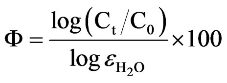
whereF is the water absorbed in percentage;
Ct is the coating capacitance at saturated state, t;
C0 is the coating capacitance at zero immersion time;
 is the relative dielectric constant of water (»80 at T = 20˚C).
It was observed during the initial period of exposure, that water uptake increased steeply for 10% - 30% PVC coatings (Figure 10), which denotes a faster diffusion of water into the coatings. The data showed highest water uptake for 30% PVC coating, followed by 20% and 10% PVCs.
Our earlier studies [14] have revealed that even during longer period of exposure, 10% and 20% PVC primers showed a very slow process of water uptake, indicating a very low loss of adhesion and no blistering on steel surface. Best performance of low PVC (10% and 20%) primers was achieved therefore a saturation of water uptake over a longer period of exposure. The diffusion coefficient of water (Dw) in the coatings was calculated using the following expression [58]:
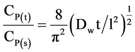
Linear plots shown in Figures 11(a)-(c) for 10% - 30% PVC coatings were used for calculating Dw values. The Dw values for 10%, 20% and 30% PVC primers were 0.2e–10 cm2·s–1, 0.3e–10 cm2·s–1 and 15.2e–10 cm2·s–1 respectively indicating an increase in diffusion coefficient values with increase in PVC contents of the primers. Lower values of diffusion coefficients at 10% - 20%
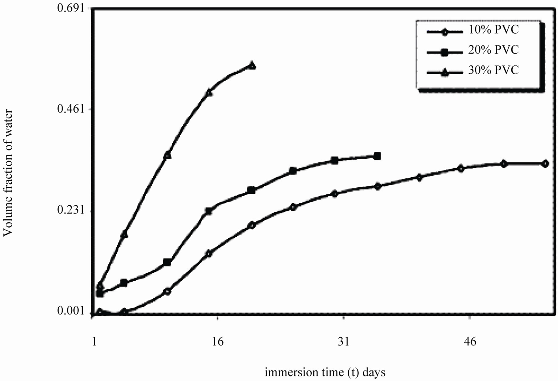
Figure 10. Volume fraction of water of EEPS as a function of immersion time exposed in 5% NaCl.
 (a)
(a)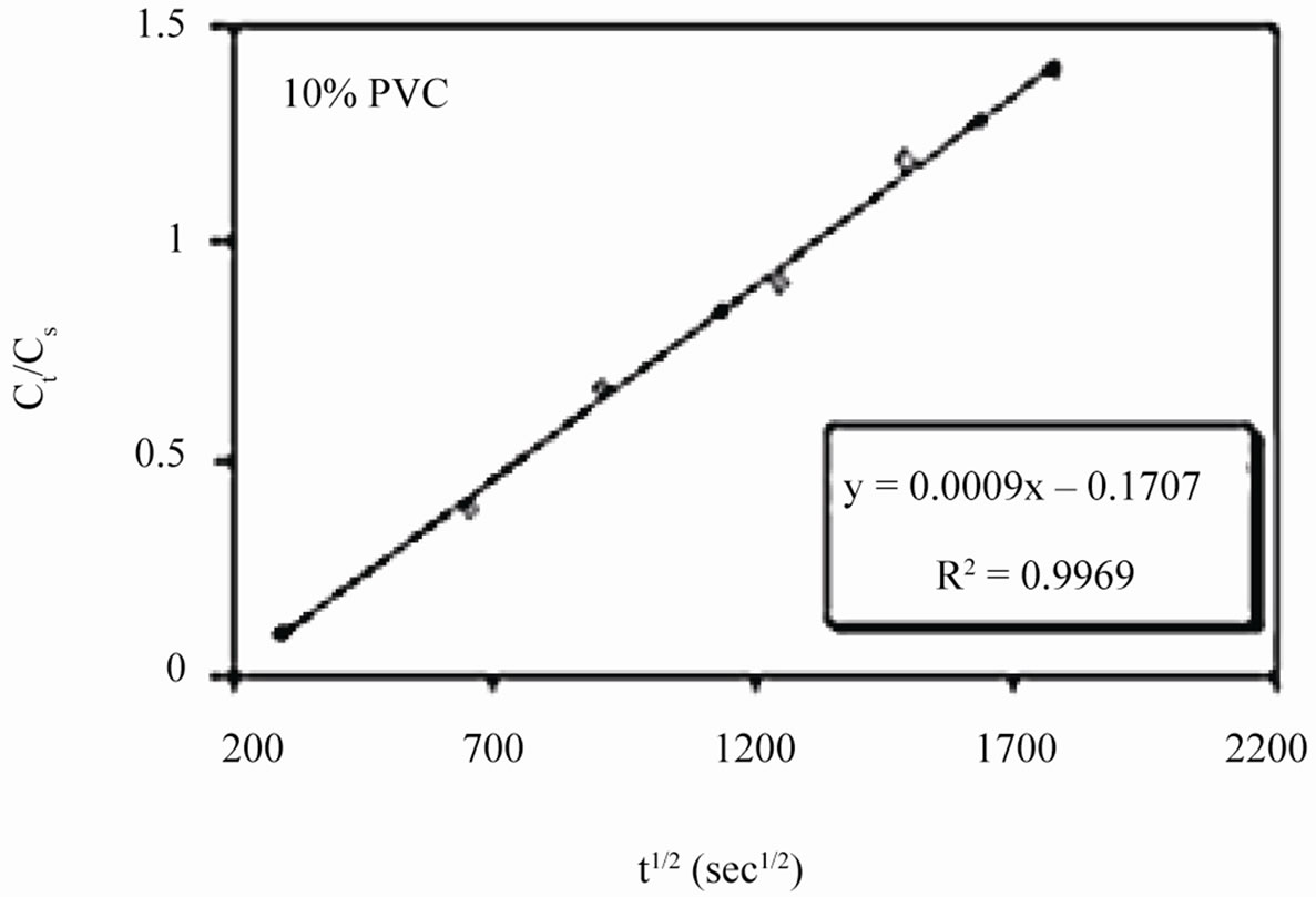 (b)
(b)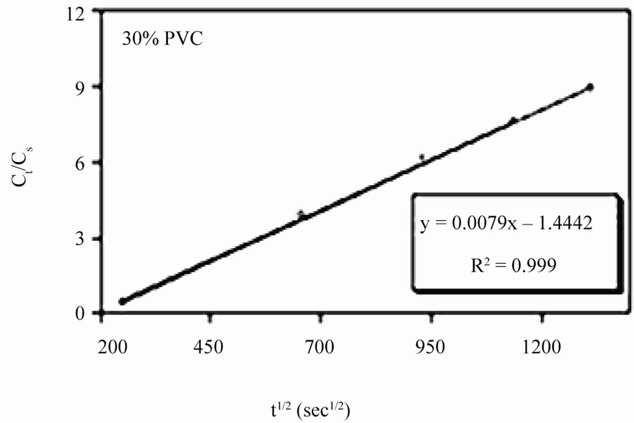 (c)
(c)
Figure 11. (a)-(c) coating capacitance normalized as a function of the square root of exposure time. Calculation of slope allows the determination of diffusion coefficient of water, Dw.
PVCs indicated low rate of water penetration through coatings, while high diffusion coefficient value at 30 PVC indicated an increase in coatings degradation. This may be attributed to the absence of any interaction between the diffused ions and the pigment [59]. Figure 12 shows the absence of linearity in water vs. square root of exposure duration indicating the deviation from the ideal pure Fickian behavior particularly during longer period of exposures. This may be a result of an interaction between the paint constituents and water contents in metal/coating interface [60].
4. Conclusions
The electrochemical characterization of eco-friendly 10% - 50% PVC primers of epoxy-ester was carried out in an aqueous solution of NaCl (5%).
v Studies had revealed that anodic reaction was more polarized than the cathodic part, which was further confirmed by polarization measurements. Studies were carried out beyond 24 hours and a positive shift in corrosion potential was observed. This might be indicating the protective nature of the corrosion products in the passive state.
v EIS study established nearly the constant value of Cdl and Rt over longer period of exposure indicating the best corrosion stability at 10% PVC, followed by 20 and 30% PVC coatings. It was also confirmed through the studies on water uptake, dielectric constant and volume fraction of water as a function of immersion time.
v Water-soluble epoxy-ester primer was prepared from epoxy resin cured with pyromellitic dianhydride, which possesses an excellent corrosion protection property. These are being considered a potential coating materials in protecting steel surface against both localized and general corrosion in aqueous solution of NaCl (5%). Further, these studies also showed that watersoluble coatings are able to offer a better protection to steel from corrosion over the conventional coatings.
v Since they are water based formulations contain no
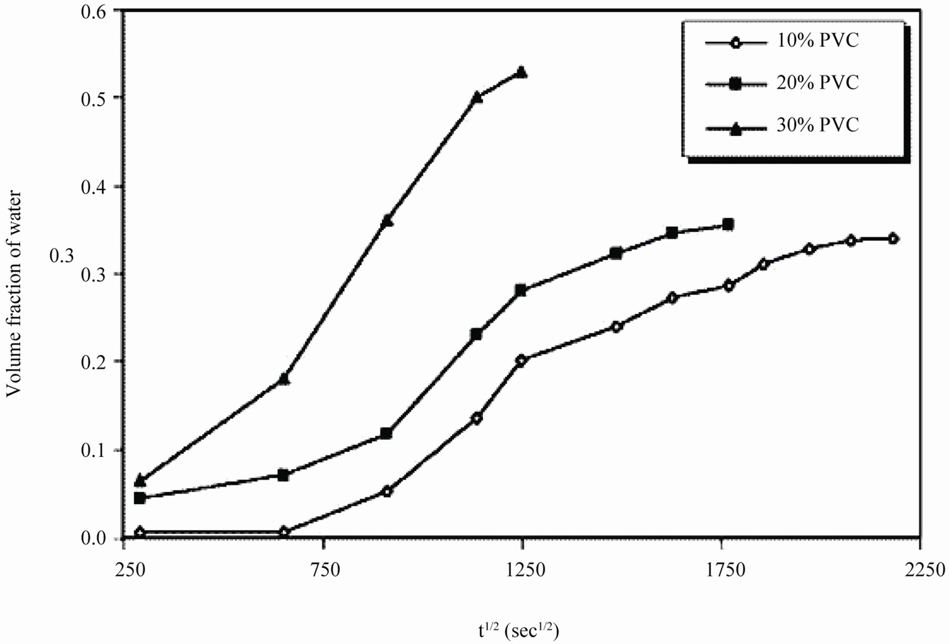
Figure 12. Linear fitting analysis of water based EEPS primer evaluating water uptake with square root of time of immersion in 5% NaCl solution.
organic solvent, therefore these can be considered as eco-friendly formulations.
5. Acknowledgements
Authors express their sincere thanks to Dr. K. Raghupathy, Scientist; Paint division, Central Electrochemical Research Institute (CECRI), Karaikudi, Tamil Nadu (India) for valuable suggestions during these investigations.
REFERENCES
- D. A. Clayton, “Prediction of coating durability,” Akzonobel Marine & Protective Coatings, Gateshead, 2002.
- Z. W. Wicks, F. N. Jones and S. P. Pappas, “Encyclopedia of Polymer Science and Technology,” 2nd edition, John Wiley and Sons, New York, 1999.
- D. Ramesh, P. Shakkthivel, A. Susaimanickam, A. Kalpana and T. Vasudevan, “Evaluation of Protective Ability of High Solid Novolac Clear Coatings through Electrochemical Techniques,” Corrosion Science and Technology, Vol. 5, No. 2, 2006, pp. 62-68.
- M. Stratmann, R. Feser and A. Leng, “Corrosion protection by Organic Films,” Electrochimica Acta, Vol. 39, No. 8-9, 1994, pp. 1207-1214. doi:10.1016/0013-4686(94)E0038-2
- P. Li, T. Tan and J. Y. Lee, “Corrosion protection of Mild Steel by Electroactive Polyaniline coatings,” Synthetic metals, Vol. 88, No. 3, 1997, pp. 237-242. doi:10.1016/S0379-6779(97)03860-5
- A. Al.Hashem, J. A. Corew and A. Hasan, “The use of Electrochemical Impedance Spectroscopy (EIS) for the determination of the properties of solvent and waterBased Paint Systems,” Surface Coatings International Part B: Coatings Transactions, Vol. 82, No. 1, 1999, pp. 26-30. doi:10.1007/BF02693014
- F. Deflorian, L. Fedrizzi, S. Rossi, F. Buratti and P. L. Bonora, “Electrochemical characterization of Organic Coatings for the Automotive Industry,” Progress in Organic Coatings, Vol. 39, No. 1, 2000, pp. 9-13. doi:10.1016/S0300-9440(00)00093-X
- S. González, M. A. Gil, J. O. Hernández, V. Fox and R. M. Souto, “Resistance to corrosion of Galvanized Steel Covered with an Epoxy-Polyamide Primer Coating,” Progress in Organic Coatings, Vol. 41, No. 1-3, 2001, pp. 167-170. doi:10.1016/S0300-9440(01)00139-4
- S. Gonzalez, I. C. M. Rosca and R. M. Souta, “Investigation of the Corrosion Resistance Characteristics of pigments in Alkyd Coatings on steel,” Progress in Organic Coatings, Vol. 43, No. 4, 2001, pp. 282-285. doi:10.1016/S0300-9440(01)00210-7
- T. Nguyen, J. B. Hubbard and J. M. Pommersheim, “Unified model for the degradation of Organic Coatings on steel in a Neutral Electrolyte,” Journal of Coatings Technology, Vol. 68, No. 855, 1996, pp. 45-56.
- H. Leidheiser and F. Mansfeld, “Coatings in corrosion mechanisms,” Marcel Dekker, New York, 1987.
- J. Kittel, N. Celati, M. Keddam and H. Takenouti, “New methods for the study of organic coatings by EIS: New insights into attached and Free Films,” Progress in Organic Coatings, Vol. 41, No. 1-3, 2001, pp. 93-98. doi:10.1016/S0300-9440(00)00155-7
- J. MacDonald, “Impedance Spectroscopy,” John Wiley & Sons, New York, 1987.
- D. Ramesh and T. Vasudevan, “Synthesis and PhysicChemical Evaluation of Water-Soluble Epoxy Ester Primer Coating,” Progress in Organic Coatings, Vol. 66, No. 2, 2009, pp. 93-98. doi:10.1016/j.porgcoat.2009.06.007
- American Society for Testing and Materials, Specification D-980, West Conshohocken, 1984.
- S. Singh, “Investigations of solvent and Water-Based Epoxy and Novolac Clear Coatings,” Paint India, Vol. 2, No. 6, 2002, p. 35.
- F. Deflorian, L. Fedrizzi, A. Locaspi and B. L. Bonora, “Testing of Corrosion Resistant Fluoropolymer Coatings,” Electrochimica Acta, Vol. 38, No. 14, 1993, pp. 1945-1950. doi:10.1016/0013-4686(93)80320-Y
- D. Pereira, J. D. Scantlebury, M. G. S. Fereira and M. E. Almeida, “The application of Electrochemical Measurements tot the study and behavior of Zinc-Rich Coatings,” Corrosion Science, Vol. 30, No. 11, 1990, pp. 1135- 1147. doi:10.1016/0010-938X(90)90061-9
- J. M. Hu, J. Q. Zhang and C. N. Cao, “Determination of Water Uptake and diffusion of Cl– ion in Epoxy Primer on Aluminum Alloys in NaCl solution by electrochemical Impedance Spectroscopy,” Progress in Organic Coatings, Vol. 46, No. 2, 2003, pp. 273-279. doi:10.1016/S0300-9440(03)00010-9
- A. Hasan, A. Al-Hashem and J. Carew, “Correlation of Atmospheric Exposure Tests with Electrochemical Impedance Spectroscopy (EIS) of solvent and Water-Based Coating Systems,” Surface Coatings International Part B: Coating Transactions, Vol. 84, No. 2, 2001, pp. 121-126. doi:10.1007/BF02699773
- F. Mansfeld, “Recording and analysis of AC Impedance Data for Corrosion Studies,” Corrosion, Vol. 37, No.5, 1981, pp. 301-307. doi:10.5006/1.3621688
- C. H. Hsu and F. Mansfeld, “Technical note: Concerning the conversion of the Constant Phase Element Parameter Y0 into a capacitance,” Corrosion, Vol. 57, No. 9, 2001, pp. 747-748. doi:10.5006/1.3280607
- D. Labouche and M. Traisnel, “A contribution to the study of New Non-Toxic Inhibitor Behaviour,” Journal of the Oil & Colour Chemists’ Association, Vol. 77, No. 10, 1994, pp. 404-419.
- P. R. Seré, D. M. Santágata, C. I. Elsner and A. R. di Sarli, “The influence of the method of application of the paint on the corrosion of the substrate as assessed by ASTM and Electrochemical Method,” Journal of the Oil & Colour Chemists’ Association, vol. 81, No. 3, 1998, pp. 128- 134.
- A. R. Di Sarli, C. I. Elsner and B. P. Joudan, “The influence of Surface Pre-Treatment on the Anti-Corrosive Capacity of Painted Galvanized Steel,” Journal of Corrosion Prevention and Control, Vol. 50, No. 2, 2003, pp. 71-81.
- C. R. Martens, “Waterborne Coatings,” Van Nostrand Reinhold Company, New York, 1981.
- N. Kouloumbi, G. M. Tsangaris, S. Nitodas and S. Kyvelidis, “Evaluation of the Anticorrosive Behaviour of Organic Coatings Applied on Galvanised Steel Surfaces,” Surface Coatings International Part B: Coatings Transactions, Vol. 81, No. 1, 1998, pp. 30-36.
- F. Deflorian, S. Rossi, P. Kamarchik, L. Fedrizzi and P. L. Bonora, “Degradation mechanism of electrodeposited coatings in Alkaline Solution,” Progress in Organic Coatings, Vol. 47, No. 2, 2003, pp. 103-111. doi:10.1016/S0300-9440(03)00023-7
- F. Mansfeld, L. T. Han, C. C. Lee and G. Zhang, “Evaluation of Corrosion Protection by Polymer Coatings Using Electrochemical Impedance Spectroscopy and Noise Analysis,” Electrochim Acta, Vol. 43, No. 19-20, 1998, pp. 2933- 2945. doi:10.1016/S0013-4686(98)00034-6
- D. Loveday, P. Peterson and B. Rodgers, “Evaluation of Organic Coating with Electrochemical Impedance Spectroscopy, Part 2: Application of EIS to Coating,” Journal of Coatings Technology, Vol. 1, No. 10, 2004, pp. 88-93.
- B. R. Hinderliter, S. G. Croll, D. E. Tallman, Q. Su and G. P. Bierwagen, “Interpretation of EIS data from accelerated exposure of Coated Metals Based on modeling of Coating Physical Properties,” Electrochimica Acta, Vol. 51, No. 21, 2006, pp. 4505-4515. doi:10.1016/j.electacta.2005.12.047
- D. Loveday, P. Peterson and B. Rodgers, “Evaluation of Organic Coating with Electrochemical Impedance Spectroscopy Part 3: Protocols for Testing Coating with EIS,” Journal of Coatings Technology, Vol. 2, No. 13, 2005, pp. 22-27.
- V. Barranco, S. Feliu and S. Feliu Jr., “EIS study of the Corrosion Behavior of Zinc-Based Coatings on steel in quiescent 3% NaCl solution. Part. 1: directly Exposed Coatings,” Corrosion Science, Vol. 46, No. 9, 2004, pp. 2203-2220. doi:10.1016/j.corsci.2003.09.032
- B. Chico, “Corrosion en union’s solapadas de aceros recubiertos, Tesis doctoral,” Universidad Complutense de Madrid, Madrid, 2001.
- F. Geenen, “Characterization of Organic Coatings with Impedance Measurements,” Ph.D. Thesis, Technische Universiteit Delft, Delft, 1991.
- S. Feliu, J. C. Galvan and M. Morcillo, “The charge Transfer Reaction in Nyquist diagrams of Painted Steel,” Corrosion Science, Vol. 30, No. 10, 1990, pp. 989-998. doi:10.1016/0010-938X(90)90206-K
- A. Amirudin and D. Thierry, “Application of Electrochemical Impedance Spectroscopy to Study Efficiency of Anticorrosive Pigments in Epoxy-Polyamide Resin,” British Corrosion Journal, Vol. 30, No. 2, 1995, pp. 128-134.
- F. Gui and R. G. Kelly, “Performance assessment and prediction of Corrosion Prevention Compounds with Electrochemical Impedance Spectroscopy,” Corrosion, Vol. 61, No. 2, 2005, pp. 119-129. doi:10.5006/1.3278166
- E. Spengler, F. L. Fragata, I. C. P. Margarit and O. R. Mattos, “Corrosion protection of Low Toxicity Paints,” Progress in Organic Coatings, Vol. 30, No. 1-2, 1997, pp. 51-57. doi:10.1016/S0300-9440(96)00668-6
- S. Haruyama, M. Asari and T. Tsuru, “Corrosion Protection by Organic Coatings,” Electrochemical Society (ECS) Proceedings, Pennington, 1987, pp. 197-207.
- H. P. Hack and J. R.Scully, “Defect Area Determination of Organic Coated Steels in Seawater Using Breakpoint Frequency Method,” Journal of the Electrochemical Society, Vol. 138, No. 1, 1991, pp. 33-40. doi:10.1149/1.2085574
- F. Deflorian, V. B. Miskovic-Stankovic, P. L. Bonora and L. Fedrizzi, “Degradation of Epoxy Coatings on Phosphatized Zinc-Electroplated Steel,” Corrosion, Vol. 50, No. 6, 1994, pp. 438-446. doi:10.5006/1.3293522
- A. A1-Hashem, J. A. Corew and A. Hasan, “The use of Electrochemical Impedance Spectroscopy (EIS) for the determination of the Protective Properties of solvent and Water-Based Paint Systems,” Surface Coatings International Part B: Coatings transactions, Vol. 82, No. 1, 1999, pp. 26-30. doi:10.1007/BF02693014
- F. Çelebi, L. Aras, G. Gündüz and I. M. Akhmedov, “Synthesis and characterization of Water-Borne and Phosphate Flame Retardant Polyurethane Coatings,” Journal of Coatings Technology, Vol. 75, No. 944, 2003, pp. 65- 71.
- V. B. Mišković-stanković, D. M. Dražić and M. J. Teodorović, “Electrolyte penetration through Epoxy Coatings Electrodeposited on steel,” Corrosion Science, Vol. 37, No. 2, 1995, pp. 241-252. doi:10.1016/0010-938X(94)00130-X
- V. B. Mišković-Stanković, D. M. Dražić and Z. Kačarević- Popović, “The sorption characteristics of Epoxy Coatings Electrodeposited on steel during exposure to Different Corrosive Agents,” Corrosion Science, Vol. 38, No. 9, 1996, pp. 1513-1523. doi:10.1016/0010-938X(96)00042-X
- V. B. Mišković-Stanković, J. B. Zotović, Z. Kačarević- Popović and M. D. Maksimović, “Corrosion behavior of epoxy Coatings Electrodeposited on Steel Electrochemically Modified by Zn-Ni alloy,” Electrochimica Acta, Vol. 44, No. 24, 1999, pp. 4269-4277. doi:10.1016/S0013-4686(99)00142-5
- Z. Z. Lazarevic, V. B. Mikovic-Stankovic, Z. Kacarevicpopovic and D. M. Drazic, “The study of Corrosion Stability of Organic Epoxy Protective Coatings an aluminum and Modified Aluminum Surfaces,” Journal of the Brazilian Chemical Society, Vol. 16, No. 1, 2005, pp. 98- 102. doi:10.1590/S0103-50532005000100015
- M. Beiro, A. Collazo, M. Izquierdo, X. R. Nóvoa and C. Pérez, “Characterization of Barrier Properties of Organic Paints: The Zinc Phosphate Effectiveness,” Progress in Organic Coatings, Vol. 46, No. 2, 2003, pp. 97-106. doi:10.1016/S0300-9440(02)00216-3
- J. J. Suay, M. T. Rodrı́guez, K. A. Razzaq, J. J. Carpio and J. J. Saura, “The evaluation of Anticorrosive Automotive Epoxy Coatings by Means of Electrochemical Impedance Spectroscopy,” Progress in Organic Coatings, Vol. 46, No. 2, 2003, pp. 121-129. doi:10.1016/S0300-9440(02)00219-9
- C. Le Pen, C. Lacabanne and N. Pébère, “Characterization of Water-Based Coatings by Electrochemical Impedance Spectroscopy,” Progress in Organic Coatings, Vol. 46, No. 2, 2003, pp. 77-83. doi:10.1016/S0300-9440(02)00213-8
- A. S. L. Castela, A. M. Simoes and M. G. S. Ferreira, “E.I.S. evaluation of attached and Free Polymer Films,” Progress in Organic Coatings, Vol. 38, No. 1, 2000, pp. 1-7. doi:10.1016/S0300-9440(99)00076-4
- P. Molera, J. Montoya and M. Del Valle, “Zinc phosphate as Corrosion Inhibitor in Epoxy Paints,” Corrosion Reviews, Vol. 21, No. 4, 2003, pp. 349-358. doi:10.1515/CORRREV.2003.21.4.349
- S. J. Wiktorex, “One-Coat Rust Preventive Painting System with Thick-Film Compounds,” Journal of Protective Coatings and Linings, Vol. 12, 1995, p. 11.
- R. M. Souto, V. Fox, M. M. Lax and S. Gonzalez, “Electrochemical Impedance Spectroscopy Investigation of the corrosion at Metallic Substrates Covered by Organic Coatings,” Journal of Adhesion Science and Technology, Vol. 14, No. 10, 2000, pp. 1321-1330. doi:10.1163/156856100742212
- M. Bethencourt, F. J. Botana, M. J. Cano, R. M. Osuna and M. Marcos, “Degradation mechanism of an Acrylic Water-Based Paint Applied to steels,” Progress in Organic Coatings, Vol. 47, No. 2, 2003, pp. 164-168. doi:10.1016/S0300-9440(03)00124-3
- D. M. Brasher and A. H. Kingsbury, “Electrical measurements in the study of Immersed Paint Coatings on metal. I. Comparison between capacitance and gravimetric methods of Estimating Water-Uptake,” Journal of applied chemistry, Vol. 4, No. 2, 1954, pp. 62-72. doi:10.1002/jctb.5010040202
- F. Galliano and D. Landolt, “Evaluation of corrosion Protection Properties of additives for Water-Borne Epoxy Coatings on steel,” Progress in Organic Coatings, Vol. 44, No. 3, 2002, pp. 217-225. doi:10.1016/S0300-9440(02)00016-4
- B. Liu, Y. Li, H. Lin and C.-N. Cao, “Electrochemical Impedance Spectroscopy Study on the Diffusion Behavior of water through Epoxy Coatings,” Corrosion, Vol. 59, No. 9, 2003, pp. 817-820. doi:10.5006/1.3277610
- s C. Perez, A. Collazo, M. Izquierdo, P. Merino and X. R. Novoa, “Characterization of the Barrier Properties of different Paint Systems: Part I. Experimental Set-Up and ideal Fickian diffusion,” Progress in Organic Coatings, Vol. 36, No. 1-2, 1999, pp. 102-108. doi:10.1016/S0300-9440(99)00030-2
NOTES
*Corresponding author.