Circuits and Systems
Vol.05 No.12(2014), Article ID:51319,7 pages
10.4236/cs.2014.512030
CFOA Based Low Pass and High Pass Ladder Filter―A New Configuration
Praween K. Sinha1, Akshay Saini1, Pranav Kumar2, Sumit Mishra3
1Electronics and Communication Department, Maharaja Agrasen Institute of Technology, New Delhi, India
2Electronics and Communication Department, University School of Information and Communication Technology, New Delhi, India
3Techno Scientific Inc., Concord, Canada
Email: praweenrsinha@rediffmail.com, akshay_saini@live.com, 222.pranav@gmail.com, mishra_sumit@gmail.com
Copyright © 2014 by authors and Scientific Research Publishing Inc.
This work is licensed under the Creative Commons Attribution International License (CC BY).
http://creativecommons.org/licenses/by/4.0/


Received 5 October 2014; revised 30 October 2014; accepted 8 November 2014
ABSTRACT
A new technique using signal flow graph for conversion of ladder based filter into CFOA based filter has been proposed. The proposed technique converts the existing LC ladder based filter into CFOA in low pass and high pass configuration. The design of low pass filter and high pass filter has been realized using the proposed technique. The proposed configuration is implemented using CFOA as an active device and all the capacitors are grounded. Simulation has been carried out using simulation software I-cap. The simulation results have been demonstrated and discussed.
Keywords:
CFOA-Current Feedback Operational Amplifier, Ladder Filter, Signal Flow Graph, Current Mode, Voltage Mode, High Pass Filter, Low Pass Filter

1. Introduction
Since the birth of electronics, there has been a need of new active devices. This led to the birth of transistors. After this voltage operational amplifier (OA) was developed, they rapidly become the main analog block and they have dominated the market since the advent of the first analog integrated circuits. However, the situation is changing now and there is inclination towards using current mode circuits. The advantages of current mode circuits over voltage mode circuits are higher signal bandwidth, larger dynamic range, greater linearity, lower power consumption, and simpler circuitry.
CM filters have received a wide attention due to their wide bandwidth, low-voltage operation and simple implementation of signal operations, such as addition and subtraction [1] -[6] . Current feedback operational amplifier (CFOA) based CM circuits have received considerable attention in many filtering and signal processing applications. CFOA-based circuits are attractive due to greater linearity, better dynamic range, high slew rate and bandwidth independent of the closed-loop gain of CFOA compared with voltage op-amps. Symbol diagram of the CFOA is shown in Figure 1.
Many attempts have been made to remove the inductor from the ladder based filter and to maintain its properties and one of the attempts is CFOA based filter. With the help of CFOA we can achieve the same characteristics of ladder based filter as they were in the original circuit and that’s all without inductor. Moreover, CFOA provides faster response and can operate at high frequency at high gain.
In this paper, active realization of ladder filter using current feedback operational amplifier (CFOA) has been presented. Performance comparison between this approach and Rathore and Khot [7] has been performed using a low pass filter.
The paper is organized as follows: heading 2 Transformation of Ladder Based Low Pass Filter into CFOA Based Low Pass Filter, heading 3 Transformation of Ladder Based Low pass Filter into CFOA Based High Pass Filter, and finally the conclusion is drawn. Given below is Figure 1 representing a CFOA building block.
2. Transformation of Ladder Low Pass Filter into CFOA Based Low Pass Filter
An improvement has been done in conventional ladder based filter to make it better and to remove inductor from it. The conversion of simple ladder based filter into CFOA based filter has been shown in the Figure 2 as follows:
2.1. Apply KCL and KVL in the Circuit
The following equations are observed after applying KCL and KVL
 (1)
(1)
 (2)
(2)
 (3)
(3)
 (4)
(4)
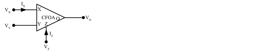
Figure 1. CFOA building block.
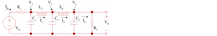
Figure 2. Simple ladder based filter.
 (5)
(5)
 (6)
(6)
 (7)
(7)
2.2. Conversion into Voltage Form
The equations are converted into voltage form to eliminate current element and we get
 (8)
(8)
 (9)
(9)
 (10)
(10)
 (11)
(11)
 (12)
(12)
 (13)
(13)
 (14)
(14)
2.3. Signal Flow Diagram
With the help of these equations we make a signal flow diagram and it has been shown in Figure 3.
2.4. CFOA Filter
And finally by using this signal flow diagram CFOA based filter is constructed as depicted in Figure 4.
2.5. Observation
The conventional and CFOA based ladder low pass filter circuits shown in Figure 5 are designed and evaluated in I-CAP using conventional resistors, inductors, capacitors and AD844 IC as CFOA.
Now the circuit is simulated in I-CAP with input voltage as 10 sin (2π10 × 10 3 t) and its AC analysis is done. The following result is obtained as shown in Figure 6.
From the graph, the cut-off frequency comes to be 410 Hz (approx.) and we can see that the response is the response for low pass filter.
2.6. CFOA Based Low Pass Filter
For CFOA we use the AD844 IC and a power supply is attached to drive it. The circuit is simulated in I-CAP with input voltage as 10 sin (2π10 × 10 3 t) and its AC analysis is done. The following result is obtained.
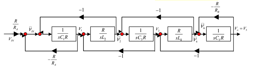
Figure 3. Signal flow graph.
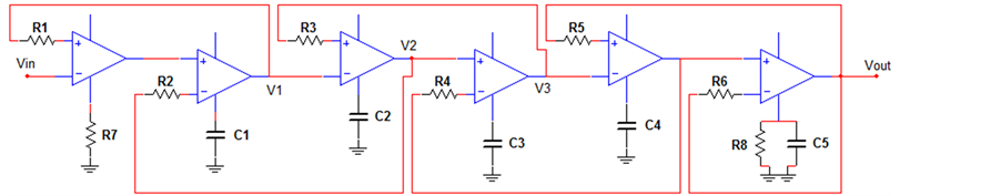
Figure 4. Conversion of signal flow diagram into CFOA block diagram.
Conventional Ladder based low pass filter
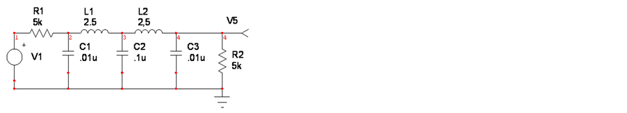
Figure 5. Ladder based LC low pass filter.
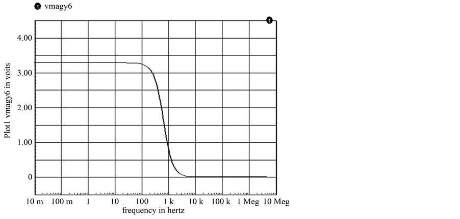
Figure 6. Response of Ladder based LC low pass.
From the graph, the cut-off frequency comes to be 430 Hz (approx.) and we can see that the response is the response for low pass filter. And both the graphs are identical to each other so the conversion is successful. The CFOA based low pass filter has been shown in Figure 7 while the response has been depicted in Figure 8.
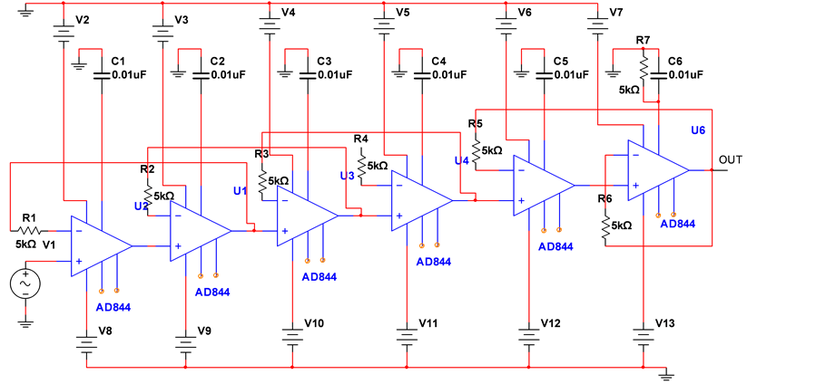
Figure 7. CFOA based low pass filter.
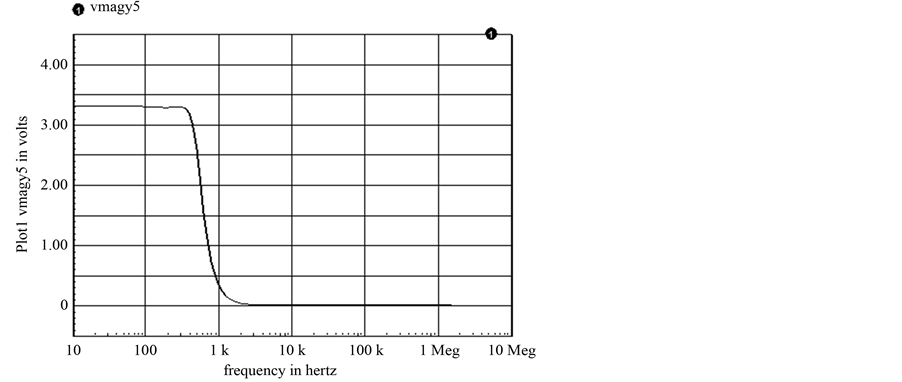
Figure 8. Response of CFOA based low pass filter.
3. Transformation of Ladder Based High Pass Filter into CFOA Based High Pass Filter
A high-pass filter (HPF) is an electronic filter that passes higher-frequency signals but attenuates (reduces the amplitude of) signals with frequencies lower than the cut-off frequency.
The actual amount of attenuation for each frequency varies from filter to filter. A high-pass filter is usually modeled as a linear time-invariant system. It is sometimes called a low-cut filter or bass-cut filter. High-pass filters have many uses, such as blocking DC from circuitry sensitive to non-zero average voltages or RF devices. They can also be used in conjunction with a low-pass filter to make a band pass filter. LC high-pass filters can be directly designed by mapping the values of a normalized LC low-pass filter into a high-pass filter. This allows use of existing tables of normalized low pass values to create high-pass filters. If 1/s is substituted for s in a normalized low-pass transfer function, a high-pass response is obtained. The low-pass attenuation values will now occur at high-pass frequencies, which are the reciprocal of the corresponding low-pass frequencies.
3.1. RLC Based High Pass Filter
The RLC high pass filter has been shown below in Figure 9.
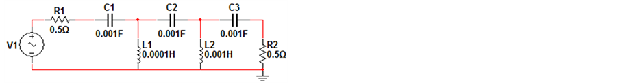
Figure 9. RLC high pass filter.
3.2. Frequency Response
The response for the ladder based high pass filter has been shown in below Figure 10.
3.3. Mathematical Analysis
Apply KCL and KVL in the circuit.
The following equations are observed after applying KCL and KVL:
 (15)
(15)
 (16)
(16)
 (17)
(17)
 (18)
(18)
 (19)
(19)
 (20)
(20)
 (21)
(21)
 (22)
(22)
 (23)
(23)
 (24)
(24)
3.4. CFOA Based Active Ladder Filter
The circuit diagram for the CFOA based high pass filter has been shown in Figure 11.
3.5. Frequency Response
The frequency response for the CFOA based high pass filter has been shown in Figure 12.
4. Conclusions
Very few methods of designing higher order ladder filter using CFOA have been explored. Rathore and Khot [7] have given a systematic method of designing CFOA based ladder filter. In that design, the summary of components used has been illustrated in Table 1.
In the proposed configuration, we have used less number of CFOA and less number of passive components. The passive components which have been used in our configuration are grounded in nature. The grounded devices are easy to fabricate in VLSI chip. The filter configuration designed in the proposed configuration has replaced the inductor completely which reduce the size of the circuit, which is a major requirement of VLSI design.
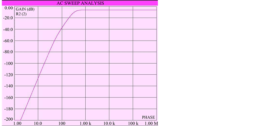
Figure 10. Response of ladder based high pass filter.
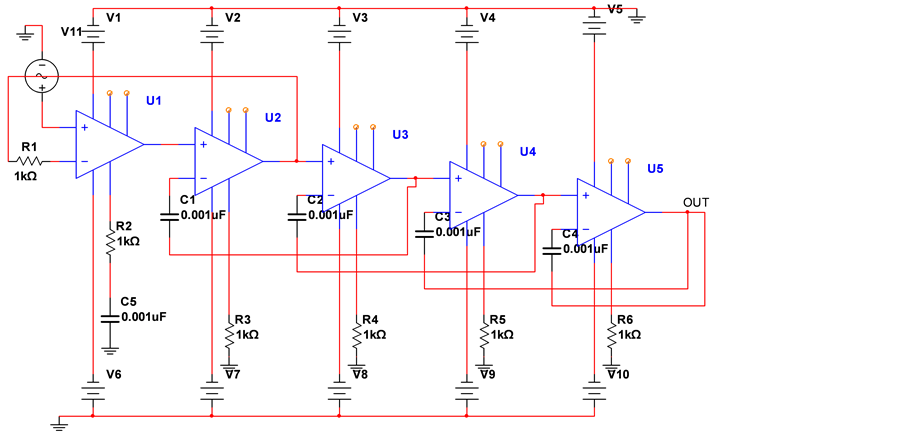
Figure 11. CFOA based high pass filter.
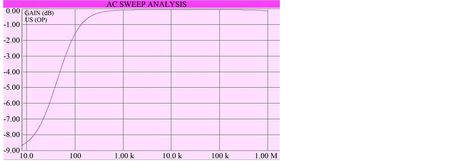
Figure 12. Frequency response of CFOA based high pass filter.

Table 1. Comparison of results of [7] and proposed realization.
In addition, after implementing the conventional and CFOA based low pass filter and high pass filter it was observed that the responses of the two filters are almost identical to their respective conventional circuits. The presence of inductor can be removed completely from the filter structure to make it less bulky and expensive. The shape of response can be set by varying resistors as variable inductance for low frequency filters are not practical. These filters imply a minimum No. of capacitors, resistance and CFOA as compared to [7] . Such filters are suitable for fabrication of integrated circuit technique as we replace the inductor with the equivalent CFOA. The above conversion can be used to produce more active low pass filters and high pass filter. So, finally we can say that the CFOA based filter is a good step towards establishment of active filters.
Cite this paper
Praween K.Sinha,AkshaySaini,PranavKumar,SumitMishra, (2014) CFOA Based Low Pass and High Pass Ladder Filter—A New Configuration. Circuits and Systems,05,293-300. doi: 10.4236/cs.2014.512030
References
- 1. Lee, S.-S., Zele, R.H., Allstot, D.J. and Liang, G. (1993) CMOS Continuous-Time Current-Mode Filters for High-Frequency Applications. IEEE Journal of Solid-State Circuits, 28, 323-329.
http://dx.doi.org/10.1109/4.209999 - 2. Ramirez-Angulo, J., Sanchez-Sinencio, E. and Robinson, M. (1992) Current-Mode Continuous Time Filters: Two Design Approaches. IEEE Transactions on Circuits and Systems II: Analog and Digital Signal Processing, 39, 337-341.
http://dx.doi.org/10.1109/82.145290 - 3. Hughes, B.J., Bird, C.N. and Macbeth, C.I. (1989) Switched Current—A New Technique for Analog Sample-Data Signal Processing. Proceedings of IEEE ISCAS, Portland, May 1989, 1584-1587.
- 4. Wu, J. and El-Masry, E. (1996) Current-Mode Ladder Filters Using Multiple Output Current Conveyors. IEE Proceedings—Circuits, Devices and Systems, 143, 218-222.
http://dx.doi.org/10.1049/ip-cds:19960490 - 5. Wu, J. and El-Masry, E. (1997) A New Approach of Design of Current-Mode Filters. Proceedings of IEEE International Symposium on Circuits and Systems, 1, 317-320.
- 6. Jurisic, D., Mijat, N. and Moschytz, G.S. (2005) Low-Sensitivity Current-Mode Active-RC Filters Using Impedance Tapering. IEEE International Symposium on Circuits and Systems, 4, 3303-3306.
- 7. Rathore, T.S. and Khot, U.P. (2008) CFA-Based Grounded-Capacitor Operational Simulation of Ladder Filters. International Journal of Circuit Theory and Applications, 36, 697-716.
http://dx.doi.org/10.1002/cta.456