Circuits and Systems
Vol. 4 No. 1 (2013) , Article ID: 27282 , 5 pages DOI:10.4236/cs.2013.41001
A Nonlinear Electrical Resonator as a Simple Touch-Sensitive Switch with Memory
1Department of Physics and Astronomy, Dickinson College, Carlisle, USA
2a.t.Q Services LLC, Carlisle, USA
Email: Englishl@dickinson.edu
Received August 30, 2012; revised September 30, 2012; accepted October 7, 2012
Keywords: Nonlinear Switch; Electrical Resonator; Bistability; Touch Sensitivity
ABSTRACT
We introduce a novel switching mechanism that relies on the bistability of a simple nonlinear electrical resonator which incorporates a varactor diode as its capacitive element. The switching action can be made fast and is self-contained in that no further circuitry is necessary. Unlike a flip-flop, whose state is flipped by applying a TTL pulse, this nonlinear switch can be engaged external to the circuit via magnetic, inductive or capacitive coupling; in this way, the switch becomes intrinsically touch-sensitive. Alternatively, the switching action can also be accomplished using frequencyshift-keying (FSK) modulation, which holds the promise of fast manipulation of the memory state. We demonstrate the potential application of these ideas by constructing a touch-sensitive LED lattice.
1. Introduction
In digital electronics, the quintessential memory element that can be switched between two states is, of course, the flip-flop. The ubiquitous SR flip-flop, for instance, consists of two crossed NOR (or NAND) gates. When no signal is applied, the state of the flip-flop remains in its previous configuration, and in order to flip it to the other state a brief voltage signal (a TTL pulse) is applied to the respective input.
Here we propose a nonlinear electrical resonator that in some ways acts like a flip-flop. As we show, the switching between its two states is accomplished via either a driver-frequency protocol (FSK modulation), or by bringing a magnet or inductor into the vicinity of the resonator; it can also be switched by capacitive coupling. Once set, the system remembers its state until another switching action is performed. However, unlike a flipflop, the element can be induced to switch from the outside of the circuit. Alternatively, a frequency modulation scheme can be employed for fast switching. Finally, we show the application of this idea by constructing a controllable LED array.
Since the switching action can occur in response to touch (via changing the capacitance) or proximity to a magnet or inductor, this resonator acts like touch-sensitive switch and is perhaps reminiscent of a “touch lamp”. When the metal housing of such a lamp is touched, its effective capacitance is increased. There are then a number of ways to convert capacitance to a digital output [1]. Even the simplest scheme incorporates a number of integrated circuit components: a fixed-amplitude AC voltage driver charges and discharges the housing, and the charging current is increased upon touch; further circuitry senses this enhanced current and switches a flipflop. Our nonlinear resonator, in contrast, does not require any further solid-state electronics to act like a switch; no comparators or flip-flops are needed.
Recently, enormous progress has been made in the field of capacitive coupling and sensing, and this has led to the development of touch-sensitive LCD screens. Here again, controllers and micro-processors are incorporated to compute the location of the touch on the screen [2,3]. The power of an array of nonlinear resonators proposed here (see discussion of the prototype) is that no such microprocessing is necessary—the switching action is intrinsic, relying primarily on the bistability of the nonlinear resonator.
Alternatively, fast switching can be accomplished by driving the system at a constant frequency, and then for a brief time interval (given by the FSK modulation pulse width) toggling to another nearby frequency. We show that the pulse width can be as small as two oscillation periods. In the resonator used here, the shortest switching pulse was 7 μs, but this time can be considerably reduced in principle by lowering the inductance value or employing varactor diodes of lower effective capacitance. There is little doubt that switching speeds could reach into the gigahertz range by scaling component properties and boosting the resonance frequency.
The idea of exploiting such resonance bistability is, of course, not new in general. It has been proposed and implemented in a number of physical systems, such as in optical cavities [4,5], in spin systems [6], and micromechanical oscillators [7,8]. Here we present a simple electronic oscillator that works on a similar principle.
2. The Resonance Circuit
Figure 1 depicts the basic nonlinear oscillator. It is comprised simply of an inductor and a varactor-diode in parallel. The latter is a capacitive element since charge is stored across the depletion layer of the pn-junction. As the width of this depletion layer is voltage-dependent, so is the effective capacitance of the diode. Additionally, the diode also allows current to flow through it (preferentially in one direction) and can be modeled as a resistive element with voltage-dependent resistance. The capacitive and resistive properties of the diode can be viewed from a circuit perspective as acting in parallel [9]. Here we choose radial-lead inductors of L =330 mH. The NTE-618 diodes are characterized by an effective capacitance of about 800 pF at zero bias voltage, as well as a large voltage-sensitivity on capacitance; when reversebiasing the diode this capacitance value decreases. The linear resonance frequency is computed as
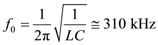 . (1)
. (1)
In order to excite this resonator, we couple it to a signal generator via a fairly large resistor R1 = 10 kW. Note that more than one copy of this resonator could be driven in this way.
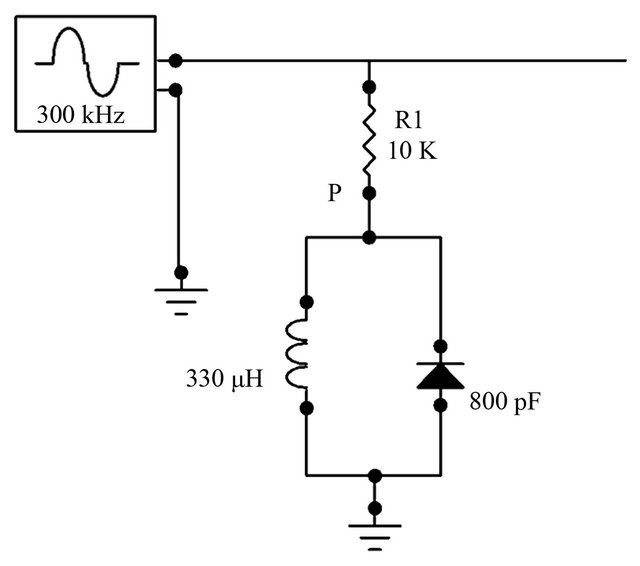
Figure 1. The basic resonance circuit consisting of an inductor and a varactor diode. The diode has effective capacitance and introduces nonlinearity into the system. The voltage response of the resonator is measured at point P.
The resonance curve for fairly large driving amplitudes is shown in Figure 2(a). For low amplitudes (not shown), the resonance frequency and profile approach those expected for linear resonance, namely a symmetric near-Lorentzian profile centered at 310 kHz. The width of the curve is given by roughly 30 kHz, which yield a relatively low quality factor,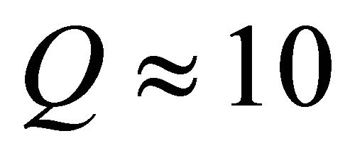 . Let us now focus on the high-amplitude trace.
At A = 3.3 V, the driving is strong enough to propel the resonator into its fully nonlinear regime. Thus, we clearly see that the resonator is characterized by soft nonlinearity as the resonance curve bends towards lower frequency (to the left). More importantly, we observe the generic feature of hysteresis in that the profile depends on the frequency-scan direction. The black trace corresponds to an up-scan in frequency, whereas the red trace corresponds to a down-scan. We see that both traces follow one another very closely, except within a narrow frequency window. Within this window, from roughly f = 247 kHz to f = 258 kHz, there are two stable solutions. Which one of them is actually realized by the system depends on the initial conditions, or in this case the history, of the system state.
The two solutions are depicted in time domain in Figure 2(b) at the driving frequency of 255 kHz (see dashed
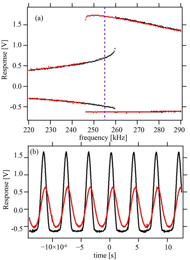
Figure 2. (a) A frequency sweep reveals the bistability region. The black trace is the response of the resonator when the frequency is slowly swept down, whereas for the red trace, it is swept up; (b) At 255 kHz, the time-response of the resonator in the two states is illustrated.
line in upper panel). The low-amplitude solution is fairly symmetric with an amplitude of just over 0.5 V. Not much current flows through the diode in the forward direction. The high-amplitude solution, however, is very non-symmetric. When reverse-biased, the voltage can reach up to 1.67 V, whereas in the forward direction it cannot exceed 0.64 V; beyond this value the current through the diode becomes large. This bistability between a small-amplitude and a high-amplitude solution forms the basis of the application of this resonator as a touch-sensitive switch.
In order to demonstrate this application, we use this circuit to drive an LED, as shown in Figure 3. The response of the resonator is connected to the base of a NPN transistor controlling the flow of current through the LED.
In this way, if the low-amplitude state is realized, the LED is not lit during any part of the cycle. This is because the base-emitter voltage of the transistor then never exceeds the necessary threshold and no current flows from collector to emitter. In contrast, when the high-amplitude state is chosen, then during parts of the cycle, the transistor is turned on allowing current to flow through the LED.
3. The Nonlinear Circuit as a Touch-Sensitive Switch
The question now is how to switch between the two states of system in the bistability region. One way to do this, of course, is to follow a driving frequency protocol, or FSK modulation. As explained in greater detail in the next section, to turn the LED on, for instance, one would for an instant move to a higher frequency. The switching time is fast due to the combination of a large resonance frequency and high Q-factor. In addition to the frequency control scheme, there exist physically more direct mechanisms.
One possible switching action relies on another interesting effect. When a magnet is brought near the radial lead inductor used in this circuit, its effective inductance
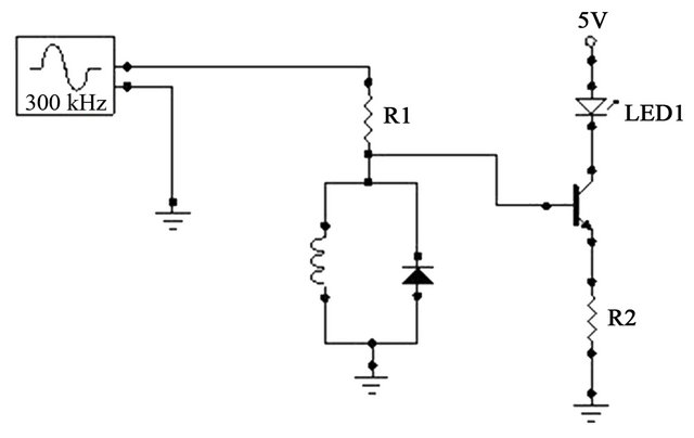
Figure 3. The nonlinear resonator can be used to control an LED in a straightforward transistor circuit.
goes down. The reason is that its core consists of a paramagnetic material, a ferrite, which can be saturated by an external magnetic field.
Now when an AC magnetic field is superimposed on this strong DC field, the result is a lower AC-inductance. This effect can be easily observed qualitatively by generating spectra like the one in Figure 2(a) while simultaneously bringing a magnet into the inductor’s vicinity— the entire spectrum then shifts to the right. To obtain quantitative data, one can use this effect to plot the linear resonance frequency, f0, against the B-field, as shown in Figure 4. From this data one could also, of course, compute an effective inductance as a function of magnetic field strength.
The main lesson of Figure 4 is that a field of roughly 100 mT is sufficient to switch the LED from an “on” to an “off”-state. Such a field easily shifts the resonance curve to the right by the minimally required 10 kHz, such that the driver at 255 kHz is no-longer situated in the bistability region but excites the lower-amplitude mode only. After the magnet is removed, the lower-amplitude state maintains itself. Thus, the LED stays off even when the magnetic field goes back to zero.
How can the LED be turned on again? It is clear that we would need an effect which increases the inductance, thus shifting the resonance curve to the left. A straightforward way of accomplishing this increase in effective inductance is via an external inductor placed in contact (or near contact) with the circuit inductor. Via the mutual inductance, the combination effectively increases the inductance, easily shifting the resonance curve to the left by at least 10 kHz. This shift, in turn, restores the highamplitude state and switches the LED back on. The LED stays on even after the external inductor is removed.
Another physically direct method of switching modulates the capacitance in the circuit rather than the inductance. This can be most easily achieved, for instance, by driving the resonators via a capacitor instead of a resistor. When the value of that capacitor is changed, the resonance frequency in turn is altered. For example, we found that when the capacitance is changed from 580 pF
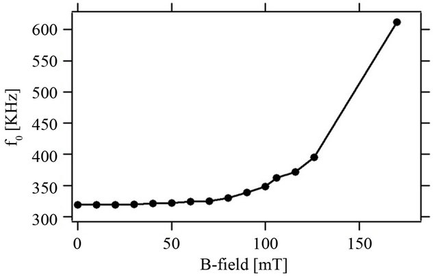
Figure 4. The dependence of the linear resonance frequency on the magnetic field strength at the inductor head. For our purposes, a 100 mT field is sufficient.
to 680 pF (keeping all other components the same), the nonlinear resonance curve shifts from 320 kHz to 306 kHz—a shift greater than the necessary 10 kHz. Thus, if we incorporate into the nonlinear resonating circuit a touch-sensitive capacitor (in place of the resistor), the switching action could be accomplished by a 15 percent increase in capacitance. Such a variation in capacitance is easily achievable, for instance, with capacitive pressure sensors [10].
4. Fast Switching
Here we demonstrate the potential of this simple nonlinear resonator as a fast memory switch. Let’s say that the system is driven in the bistability region and the low-amplitude state is realized. How fast can the system by switched into the high-amplitude state? As shown in Figure 5, the frequency is abruptly changed from fd = 257 kHz to 290 kHz during a pulse of varying duration (black trace); after the pulse the frequency returns to the original value. This type of digital frequency modulation is also referred to as FSK modulation. The blue trace depicts the response of the oscillator. Note that at 260 kHz, the period is 3.8 ms. A FSK pulse of 5 ms duration is not quite long enough to allow the state to migrate to the high-amplitude solution. However, if the pulse width is lengthened to 7 ms, then the switching is accomplished.
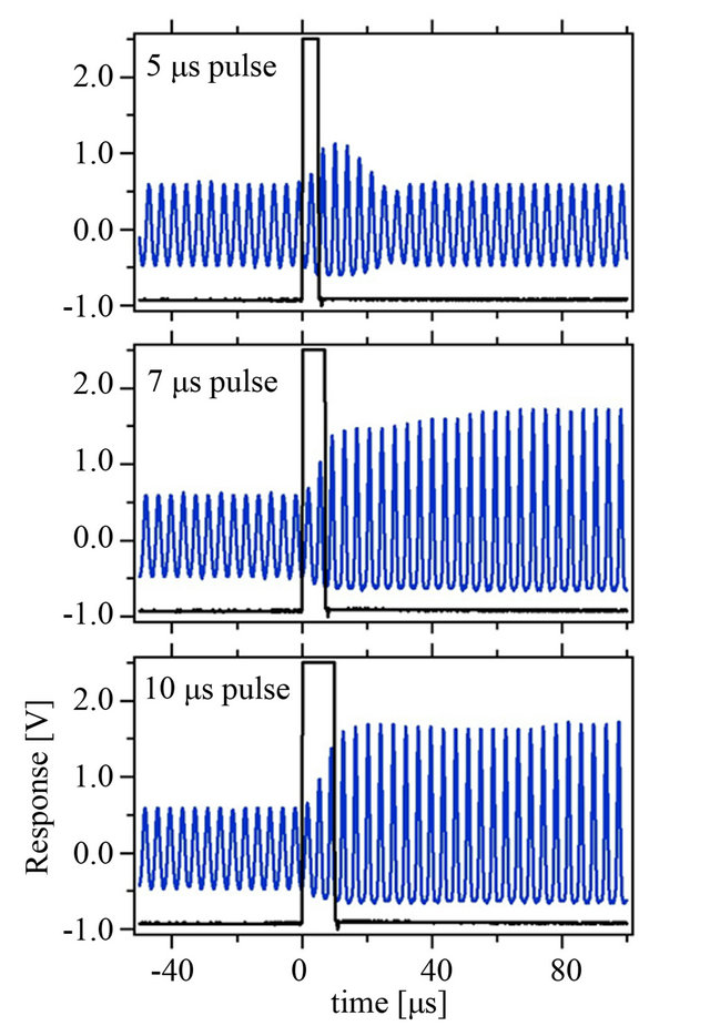
Figure 5. The system’s response to FSK modulation. The pulse indicates the driving frequency: outside the pulse, fd = 257 kHz, and inside the pulse 290 kHz. (a) The switch does not quite turn on at a pulse width of t = 5 ms; (b) For t = 7 ms, a state change is barely accomplished; (c) t = 10 ms easily propels the system into the high-amplitude state.
Thus, the pulse width is only required to be roughly two periods of oscillation.
These results suggest a way to boost switching speeds further by scaling up the frequencies. This, in turn, can be achieved by using smaller inductors, and/or by selecting varactor diodes of smaller effective capacitance values (but with sufficient nonlinearity). In order to reach industry standards for commercially-available fast flipflops (CMOS), which feature maximum clock speeds of 80 - 200 MHz, the resonance frequency here would have to be increased by a factor of 1000. Since our test circuit currently incorporates fairly large inductance and capacitance values, we expect this to be achievable while aiding the goal of miniaturizing the resonator.
5. A Prototype System
All the pieces are now in place to construct a prototype system comprised of a number of controllable LEDs. To demonstrate the feasibility of the concept, we chose to build a three-by-three LED lattice, as illustrated in Figure 6. Each LED is controlled by its own resonance circuit. A two-sided pen is also shown in the figure. It consists of a magnetic tip on one side and an inductor on the other. This way, by touching a particular inductor in this array, its respective LED can be turned on and off. The effect remains robust even when a plastic cover is placed over the array (although it cannot exceed a certain thickness, otherwise the mutual inductance becomes too small). One important consideration in the design of such an array of LEDs is component uniformity. Commercially available inductors usually have a tolerance of perhaps 5 percent. This variance is too large for the purpose of this application, and so a post-selection of inductors is necessary. If this is not done, a single driver frequency will not fall into the bistability window of all resonators.
Note that any pattern of light can be induced in this LED array in a physically direct way, without the use of microprocessors. To erase a pattern and turn all LEDs off,

Figure 6. A 3 × 3 array of controllable LEDs. The pen at the top is used to switch the LEDs by touch.
a momentary decrease in driver frequency is all that is needed. If all LEDs are to be lit, a quick shift to larger frequency will accomplish it. In this way, this switching scheme yields flexibility and external control in a straightforward manner.
6. Conclusions
We have demonstrated a touch-sensitive switch based on a simple nonlinear electrical resonator. The bistability and hysteresis properties of the circuit provide the novel multi-mode switching functionality depending on magnetic, inductive or capacitive input. The circuit uses minimal electronic components and does not require extensive programmable logic control systems inherent to current touch-sensitive solutions. This economical design has superior response times to other current touch-sensitive solution. Furthermore, the switching time is a direct function of the resonator circuit properties, and this implies that a simple choice of resonator components can be used to “tune” the circuit response time over a range of several decades. The multi-mode switching characteristics add further dimension to these switching circuits extending the applicability to a host of new applications.
This work preludes possible applications for a more general class of nonlinear resonator networks described in literature. These topologically repeating networks allow “smart” circuit design with cheap components while using no digital programmable components. For instance, a simple local input to a node in this network can shift the resonance characteristics of the circuits causing energy to be moved between two specific nodes. This allows for a variety of power applications where arbitrary energy transfer not limited to electric is easily achieved.
We are currently prototyping several applications in illumination, signage, memory storage, and climate control applications with this general class of nonlinear resonator circuits.
7. Acknowledgements
L.Q.E. was supported by an NSF PFI/ITN Seed Assistance Grant 4437-DC-NSF-7466.
REFERENCES
- M. Yamada and K. Watanabe, “A Capacitive Pressure Sensor Interface Using Oversampling Delta-Sigma Demodulation Techniques,” IEEE Transactions on Instrumentation and Measurement, Vol. 46, No. 1, 1997, pp. 3- 7. doi:10.1109/19.552148
- M. Lee, “The Art of Capacitive Sensing,” EE Times (An UBM Electronics Publication), Planet Analog Supplement, 2006.
- J. Schöning, et al., “Multi-Touch Surfaces: A Technical Guide,” Technical Report TUM-I0833, 2008.
- H. M. Gibbs, “Optical Bistability: Controlling Light with Light,” Academic Press, New York, 1985.
- H. Wang, D. Goorskey and M. Xiao, “Controlling Light by Light with Three-Level Atoms Inside an Optical Cavity,” Optics Letters, Vol. 27, No. 15, 2002, pp. 1354-1356. doi:10.1364/OL.27.001354
- D. Gourier, E. Aubay and J. Guglielmi, “Bistable Switching of Nuclear Polarization States in Gallium Oxide,” Physical Review B, Vol. 50, No. 5, 1994, pp. 2941-2952. doi:10.1103/PhysRevB.50.2941
- H. B. Chan and C. Stambaugh, “Fluctuation-Enhanced Frequency Mixing in a Nonlinear Micromechanical Oscillator,” Physical Review B, Vol. 73, No. 22, 2006, Article ID: 224301. doi:10.1103/PhysRevB.73.224301
- J. Casals-Terre, A. Fargas-Marques and A. M. Shkel, “Snap-Action Bistable Micromechanisms Actuated by Nonlinear Resonance,” Journal of Microelectromechanical Systems, Vol. 17, No. 5, 2008, pp. 1082-1093. doi:10.1109/JMEMS.2008.2003054
- F. Palmero, L. Q. English, J. Cuevas, R. Carretero-Gonzalez and P. G. Kevrekidis, “Discrete Breathers in a Nonlinear Electric Line: Modeling, Computation, and Experiment,” Physical Review E, Vol. 84, No. 2, 2011, Article ID: 026605. doi:10.1103/PhysRevE.84.026605
- J. Han and M. A. Shannon, “Smooth Contact Capacitive Pressure Sensors in Touchand Peeling-Mode Operation,” IEEE Sensors Journal, Vol. 9, No. 3, 2009, pp. 199-206. doi:10.1109/JSEN.2008.2011090