Wireless Engineering and Technology
Vol.07 No.01(2016), Article ID:61480,11 pages
10.4236/wet.2016.71001
New Approach on Development a Dual Axis Solar Tracking Prototype
Nader Barsoum, RinoeNizam, Elvin Gerard
Department of Electrical & Electronic Engineering, Faculty of Engineering,Universityof Sabah, Kota Kinabalu, Malaysia

Copyright © 2016 by authors and Scientific Research Publishing Inc.
This work is licensed under the Creative Commons Attribution International License (CC BY).


Received 8October 2015; accepted 23November 2015; published 26November 2015

ABSTRACT
To track the sun in two directions that is elevation and azimuth, a dual-axis tracking prototype is developed to capturethe maximumsun rays by tracking the movement of the sun in four different directions. One axis is azimuth which allows the solar panel to move left and right. The other axis is elevation and allows the panel to turn up and down. The result of this new development provides the solar panels with extensive freedom of movement. This new approach will make use of the Light Depending Resistor (LDR) which is important to detect the sun light by following the source of the sun light location. AutoCAD software is being used to design the draft in 2-dimension (2D) for the hardware dual axis solar tacker. Sketch Up software is being used to sketch the drawing to be more real in 3-dimension (3D). Proteus software is being used to design the circuit for the Arduino UNO microcontrollersand H-BridgeIC chip. This implemented system can save more energy and probably offers more reduction in cost.The paper discusses the process of hardware development and the control process of tracking the sun, as well as the circuit design.
Keywords:
Elevation, Azimuth, Altitude, LDR, AutoCAD, Sketch Up, Proteus H-Bridge IC, Arduino Microcontroller

1. Introduction
The demand on electricity and its price iscontinuously increased over the time. Solar energy has become a preferred alternative to meet the increasing in electricity demand because of its ubiquity, abundance, and sustainability, regardless the intermittency of sunlight, solar energy is widely available and completely free of cost [1] . According to [2] ,photovoltaicis solid-state device that simply makes electricity out of sunlight, silently and with little to no maintenance, no pollution and no significant depletion of material resources. However, it is costly to install but in a long term it can save more energy and offers more reduction in cost.
A solar tracker is a device for orienting a day lighting reflector, solar photovoltaic panel or concentrating solar reflector or lens toward the sun. Solar powered equipment works best when pointed at or near the sun, so a solar tracker can increase the effectiveness of such equipment over any fixed position, at the cost of additional system complexity. The tracker will enable the panel to follow the path of the sun and produce more power as it absorbs more sunlight. Concentrators, especially in solar cell applications, require a high degree of accuracy to ensure that the concentrated sunlight is directed precisely to the powered device.
By using single axis solar tracker can only capture the minimum power tracking sunlight in one direction which is the elevation movements from east to west by rotating the structure along the vertical axis. According to [3] , the use of single-axis tracking can increase the electricity yield by as much as 27% to 32%, but by using dual axis solar tracker, it can capture the maximum sunlight in two movements that is elevation and azimuth and in the same time it can receive the full capacity of lux. [3] reports that dual-axis tracking increases the electricity output as much as 35% to 40%. Solar tracker is an electro-mechanical device for orienting a solar photovoltaic panel toward the sun trackers. Several methods and designs of sun tracking systems have been proposed, designed and implemented, main are included in [2] [4] and [5] . Since solar tracking PV panels include moving parts and control elements relatively expensive, single-axis variant seems to be more cost-effective than the double-axis alternative, especially for small PV power plants. To get maximum intensity of light and zero voltage difference (error degree) the position of panel must always perpendicular to the light source [6] . Uses of Single Axis throughout the year do not maintain the output power. The position of sun will change from the position of installed solar tracker and make the panel no more perpendicular to the sun which affects the output power. Therefore, dual-axis solar tracking makes the movement of solar panel to be always perpendicular to the sun [7] . The tracker will track the sun throughout the years [8] [9] and maintaining the output power generate by the solar panel.
A DC geared motor is a device that uses DCelectricity to produce mechanical energy. The energy in electric current causes the DC geared motor to spin. Any devices attached to the motor can then take advantage of this spinning motion to create another type of motion. In a gear motor, the magnetic current turns gears that are either in a gear reduction unit or in an integrated gear box. A second shaft is connected to these gears. Gear head or gear motor was used in solar tracker which has the advantage of producing high torque [10] .
A combination of resistors, capacitors, amplifiers, logic gates, diodes, and transistors used to form a comparison and driver circuit. The output of the comparing circuit powers a driver circuit, which in turn powers a motor and changes direction according to which sensor receives a higher amount of illumination. This orients the solar panel to be perpendicular to the sun [11] . This paper shows the development of a simulated model of dual axis solar tracker by using Proteus, AutoCAD and Sketch Up software. Programming Arduino (ATmega328p) microcontroller to control the rotation of DC motor is also given depending on the voltage differences from the sensor LDR based on intensity of sunlight.
2. Process of Hardware
This section explains the workflow of modelling and simulation of the prototype hardware:
2.1. Block Diagram
Figure 1 shows the block diagram of a dual axis solar tracker. 4 LDR sensors are placed adjacent to the solar panel and will be activated when light is detected. An activate signal will be sent to the microcontroller and when the signal is received, the Arduino microcontroller will trigger the 2 drivers and activate the 2 motors.
2.2. AutoCAD
AutoCAD is a computer-aided drafting software program used for creating blueprints for buildings, bridges and computer chips. AutoCAD is a 2-D and 3-D software application used in architecture. For the hardware tracker,Figure2 shows the process of building the model and Figure 3presents the model of the dual axis solar tracker.
The DC motor A shown inFigure 3will turn in azimuth axis directions to support the movement of all parts. Then, the top DC motor B will turn in elevation directions so that the LDR can detect the source of sunlight. The circuit will be behind the DC motor A and the solar panel will be in the middle. After the LDRs detect the sunlight, then the solar panel will start its function to convert solar energy into electricity.
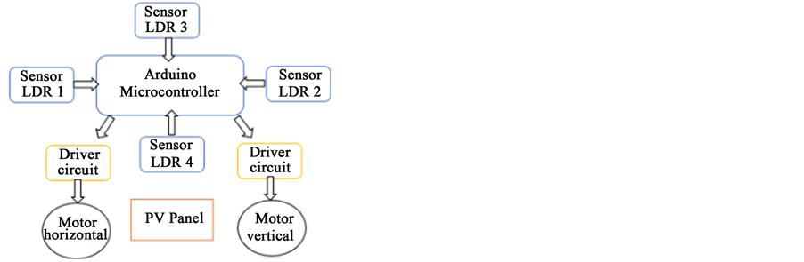
Figure 1.Block diagram.
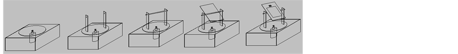
Figure 2.Process of designing the model using AutoCAD.

Figure 3.The model of the dual axis solar tracker using AutoCAD.
2.3. SketchUp
Sketch Up is the most intuitive way to design, document and communicate the ideas in 3D. Sketch Up is a 3D modelling computer program for applications such as architectural, interior design. By using the Sketch Up software Figure 4shows the process of the designing model andFigure 5presents the model of the hardware dual axis solar tracker.
2.4.Proteus and H-Bridge IC
By using Proteus software thehardware circuitis combined by two parts, Arduino Uno microcontroller and the H-Bridge IC which is used to control the motor. The process started with the input signal by the sensor which is the light intensity (LUX used in the software) going into the microcontroller. For Arduino, theanalog-to-digital converter (ADC) already exists on the input pins. Therefore, the LDR can be directly connected into it. Inside microcontroller a comparison between the voltages outputs from each LDR occur. There are 5 cases are made by using “if else” statement. The first case is when LDR sensor 1 received the highest light intensity. Therefore the output voltage V1 is higher than the other sensor. Case number 2, 3 and 4 is the same as case number 1 but at this time with different LDR sensor receives the highest light intensity. Case number 5 is when all the LDR sensors received the same light intensity, thus producing the same value of output voltage. At this point, com-
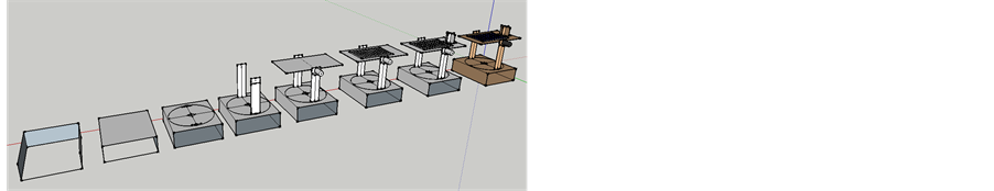
Figure 4.Process of designing the model using Sketch Up.
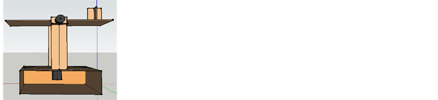
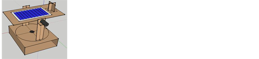
Figure 5.The model of dual axis solar tracker using Sketch Up.
parison between sensors is stopped, and then a LOW signal will be sent to H-bridge from micro-controller to turn off the signal for DC motor. When there is a difference between the sensor outputs voltages aHIGH signal is sent to the H-bridge to control the DC motor rotation to move until same voltage output value achieves by the sensors.Figure 6shows H-bridge L293D discrete component in Proteus.
Based on the IC schematic diagram pin 2, 7, 10 and 15 are the input for the bridge. Pin 1 and 9 are used to turn on the port so that the DC motor can be controlled. Pin 3, 6, 11 and 14 are the output used to connect the DC motor. Positive polarity of the motor will be connected to pin 3 and 11. The simulation will be based on programming language which firstly compares the voltage differences from the two sensors and after some occasion, a signal will be send to the input pin of this H-bridge.
2.5. Prototype Fabrication
This part explains about the process of the fabrication of the prototype dual axis solar tracker. The first part to be done is the base of the dual axis solar tracker. A square box is used for the bottom of the base so that it can hold the top part. Then a round circle board with diameter 26cm × 20cm × 2mm is used to support the motor in the middle of the board so that the motor can turn azimuth axis position. Then abeamof 5cm × 20cm × 2mm is used to support the top part so that it can hold stronger. Another square board of 22cm × 16cm × 2mm is in the top part to support the solar panel and also the LDR. To support the square board at top, a rod metal shaft which goes through the centre of the beam is connected with another DC motor so that the top part can turn the elevation axis. Figure 7 shows the full hardware combined with the circuit.
2.6. Circuit Fabrication and Programming
The programming part consists of three sections. Sensor input, voltage comparison and input signal for H-bridge. The program is too long and not typed in this paper. Therefore, only small part of the programmed is given as follows:
int sensorPinA0 = A0; //set as an input for Sensor 1;
int sensorPinA1 = A1; //set as an input for Sensor 2;
int sensorPinA2 = A2; //set as an input for Sensor 3;
int sensorPinA3 = A3; //set as an input for Sensor 4;
constint motor1Pin = 3; //h-bridge to arduino;
constint motor2Pin = 4; //h-bridge to arduino;
constint motor3Pin = 10; //h-bridge to arduino;
constint motor4Pin = 11; //h-bridge to arduino;
constint enablePin1 = 9; //h-bridge to arduino;
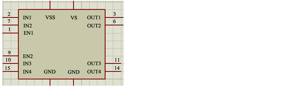
Figure 6.H-bridge L293D IC in Proteus.
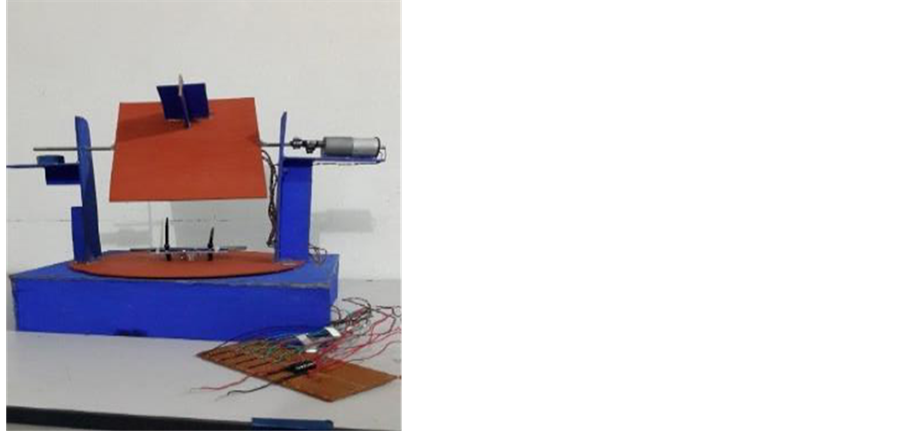
Figure 7.Full part combined with circuit.
constint enablePin2 = 5; //h-bridge to arduino;
int sensorValueA0 = 0;
int sensorValueA1 = 0;
int sensorValueA2 = 0;
int sensorValueA3 = 0.
The above description is the declaration of input and output pin which is used on the microcontroller and H-bridge. This code was written in Arduino compiler (saved as .ino file) and also compiled on the same software.There are five cases being simulated and at the same time there are four LDR uses as input sensor. Therefore, each of these sensors has its output voltage resulting from the voltage divider (Figure8).
When the LDR1 is getting the light source in position 1 (left and bottom), then the Arduino is getting the signal from the LDR1 and hence the Arduino will send the signal to both of DC motors. The first DC motor (bottom) will rotate anticlockwise and the second DC motor (top)will also turn anticlockwise. The same thing will happen when the LDR2 is getting the light source in position 2 (right and bottom). This is because from the coding that has been set in the software part. For position 3, when the LDR4 is getting the light source (right and top), same thing happen to the Arduino which is getting the signal from LDR4 then the Arduino will send the signal to both of DC motor. The opposite happen compare to the position 1 and 2, for the first DC motor (bottom) will rotate the clockwise and for the second DC motor (top) will also turn clockwise.
The overall outputs that had been produced by the hardware dual axis solar tracker with 4 different position of LDR are shown in Figure 9. Table 1explains the result that had been produced by the 4 LDRs. LDR1 that places in the top left and bottomgives the output to the DC Motor A (Bottom) will turn anticlockwise while the
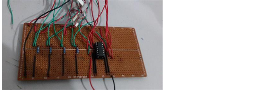
Figure 8.The complete circuit of the H-Bridge IC chip.
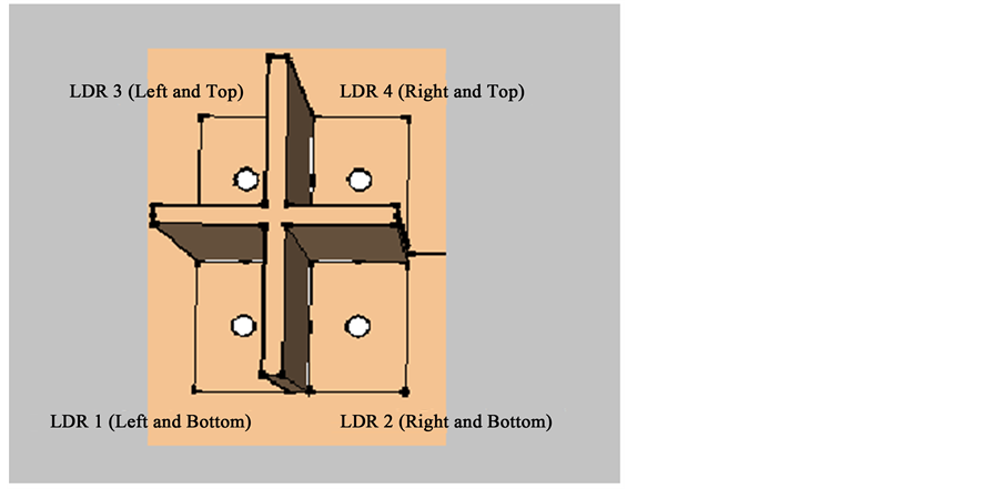
Figure 9.The overall result of the four position of the LDR.

Table 1.The four results of the LDR.
DC Motor B (Top) will turn anticlockwise also. The same rotation will happen for the DC Motor of LDR3 (Left and Top). Next LDR2 that places in the right and bottomgives the output to the DC Motor A (Bottom) will turn clockwise while the DC Motor B (Top) will turn clockwise also and the same rotation will happen for the DC Motor of LDR4 (Right and Top). Basically, the same output will produce by LDR1 and LDR3 and so for LDR2 and LDR4.
3. Tracking Process
DC motor movement will follow the condition of the LDR. In dual axis solar tracking system, there are 2 DC motors. One motor is used to control elevation axis and another motor is used to control azimuth axis.
Case 1: LDR1 light intensity > LDR2, LDR3 and LDR4
Figure 10shows that LDR sensor 1 has the highest intensity of light hit on it thus producing a higher voltage output than the other sensors. In this simulation, the highest intensity of light is fixed to 15.1 lux and the lowest is at 0.1 lux. This condition is applied to case 2, 3 and 4 except for case 5 where the simulation is about to test the motor rotation if the intensity of light on each sensor is fixed to 15.1 lux. For case 1, DC motor A rotates in clockwise direction and DC motor B rotates counter-clockwise direction. When applied to the real situation, DC motor A will control the movement of elevation axis of the solar tracker and DC motor B will control the azimuth axis of solar tracker.
Case 2: LDR2 light intensity > LDR1, LDR3 and LDR4
Figure 11shows the condition when LDR sensor 2 gains the highest intensity of light. The position of light in this case is at position 2. Therefore, in order to make all the sensor gain the same intensity of light the elevation axis has to move counter-clockwise and the azimuth axis move clockwise as shown by the DC motor A and B in Figure 11.
Case 3: LDR3 light intensity > LDR1, LDR2 and LDR4
Figure 12 is the condition when light is placed on position 3, thus LDR sensor 3 gains the highest intensity of light compared to other sensors. In order for the entire LDR sensor to achieve the same light intensity the elevation axis which is DC motor Brotates clockwise. On the other hand, azimuth axis which is controlled by DC motor A will rotate counter-clockwise.
Case 4: LDR4 light intensity > LDR1, LDR2 and LDR3
Figure 13shows the condition when LDR sensor 4 received the highest intensity of light and the position of light is at position 4. At this case, the solar tracker needs to rotate its elevation axis clockwise and the azimuth axis must rotate counter-clockwise. In this simulation, DC motor A moves counter-clockwise and DC motor B will rotate clockwise.
Case 5: LDR1 light intensity = LDR2 = LDR3 = LDR4
Figure 14 is the final case of programming part. This compares the entire sensor on one fixed values of 15.1 lux which means all the sensors are receiving the same light intensity. The position of light is placed at position
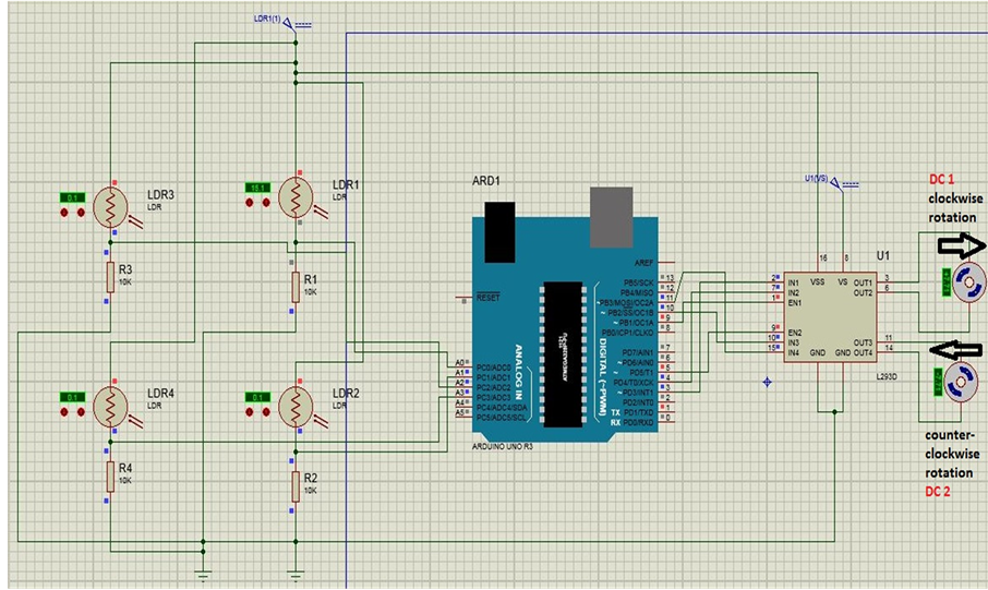
Figure 10.Condition for LDR1 higher than the other sensor.
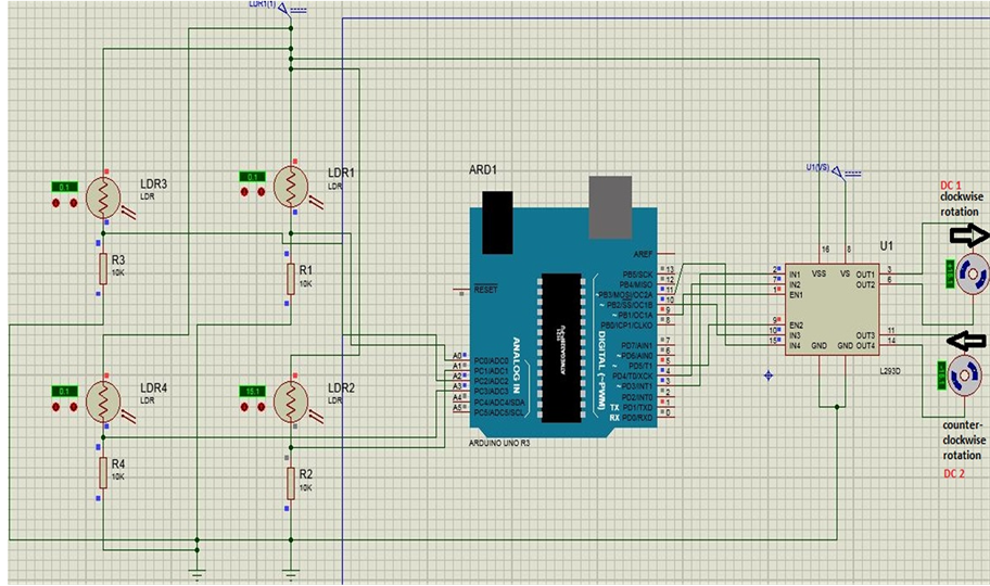
Figure 11.Condition for LDR2 higher than the other sensor.

Figure 12.Condition for LDR3 higher than the other sensor.
5 where light distributed are equally. Therefore, the DC motor A and B stay at the same position instead of rotating. In real applications, this is where solar panel is perpendicular to the sunlight and the production of power can be improved.
Table 2shows the real time voltage output measurements of the 4 LDR sensors when the light intensity varies its position with respects to the sensor positions. It shows the output voltage of the LDR sensor is not that
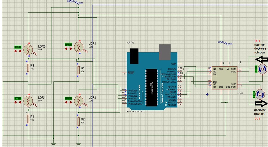
Figure 13.Condition for LDR4 higher than the other sensor.
Table 2.Voltage output of LDR sensor.
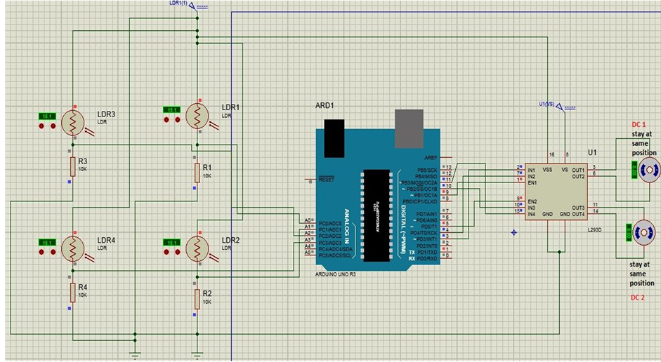
Figure 14.Condition when the entire LDR sensors received the same light intensity.
stable. There are some uncertainty occur in each of the sensor values. This is because the connection of LDR sensor towards the microcontroller is by using a voltage divider apart from the LDR sensors directly. There a 5v supply going into LDR and this LDR connected to a 10 kohm resistor so that the voltage output can be calcu-
lated by using the formula below

The first reading is taken at position 1. LDR3 will receive the highest amount of light for reading number 1 and 2 therefore its output voltage is higher than the other sensor. Reading number 3 is taken at position 4 which make LDR1 and LDR2 values are slightly higher than the other 2 sensors. Reading number 4 and 5 is taken at position 3 which eventually make the voltage output of LDR2 and LDR3 higher. Reading number 6 to 15 is taken at position number 5 which the light is on top of the entire 4 sensor. Here, the entire sensor has a constant voltage output except for LDR3 reading, which a bit higher than other sensor and this may be caused by the light position which is more towards LDR3. Reading number 16 is where the entire four sensors achieved the same output voltage with some uncertainty for about 0.05V which is the difference from LDR2 and LDR4. By looking at readings 16 to 20, all output values achieved the same peak which is about 4v. This is the ideal position of the solar tracker where the panel will be perpendicular to the light source. Light source for reading number 17 to 20 is still in the same position of reading number 16.The readingsare taken for many times in order to get accurate voltage output values for the sensor.
4. Conclusions
Both single-axis and dual-axis are highly efficient in terms of the electrical energy output when compared to the fixed mount system. Compare to single axis solar tracker, the Dual axis tracker is having more efficiency. The main contributions of this work are the development of a two axis solar tracker prototype that uses four sensors to predict the sun apparent position. By using the AutoCAD software, it helps to design the draft for the hardware dual axis solar tracker. Sketch Up is also software being used for confirmation of this purpose. With this software, 3D design about the prototype modelcan bemade. It helps to make the sketch better and more accurate. The Arduino and Proteus help to make the circuit not so difficult,which save a lot of time and energy. In this system further research is needed to make the system more precise and complete.
In this paper, all the objectives have been achieved which are, firstly, to design a model of dual axis solar tracker by using software. The design has been showed and analyzed. Secondly, to program the micro-controller on Arduino (ATmega328p) so that rotation of DC motor can be controlled by microcontroller and H-bridge. The programming part consists of 5 cases which has been stated and analyzed. Thirdly, to investigate the voltage differences from the sensor (light depending resistor LDR) based on intensity of light received by the sensor. The output has been plotted into a graph and has been analyzed.
Cite this paper
NaderBarsoum,RinoeNizam,ElvinGerard, (2016) New Approach on Development a Dual Axis Solar Tracking Prototype. Wireless Engineering and Technology,07,1-11. doi: 10.4236/wet.2016.71001
References
- 1. Chin, C.S., Babu, A. and McBride, W. (2011) Design, Modeling and Testing of a Standalone Single Axis Active Solar Tracker Using MATLAB/Simulink. Renewable Energy, 36, 3075-3090. http://dx.doi.org/10.1016/j.renene.2011.03.026
- 2. Prasad, D. and Snow, M. (2005) Designing with Solar Power: A Source Book for Building Integrated Photovoltaic (BiPV). Earthscan, London, 23.
- 3. Appleyard, D. (2009) Solar Trackers: Facing the Sun. Renewable Energy World, 12. http://www.renewableenergyworld.com/rea/news/article/2009/06/solar-trackers-facing-the-sun
- 4. El-Moghany, M.S. and Hamed, B.M. (2012) Two Axis Tracker Using Fuzzy Controller via PIC16F887a. The 4th International Engineering Conference—Towards Engineering of 21st Century, Gaza, 15-16 October 2012.
- 5. Salem, F.A. (2013) Mechatronics Design of Solar Tracking System. International Journal of Current Engineering and Technology, 3, 417-429.
- 6. Goetz Berger, A., Hebling, C. and Schock, H. (2002) Photovoltaic Materials, History, Status and Outlook. Materials Science and Engineering: R: Reports, 40, 1-46.
- 7. Barsoum, N. and Vasant, P. (2010) Simplified Solar Tracking Prototype. Global Journal of Technology and Optimization (GJTO), 1, 38-45.
- 8. Barsoum, N. (2011) Fabrication of Dual-Axis Solar Tracking Controller Project. Intelligent Control and Automation, 2, 57-68.
- 9. Barsoum, N. (2011) Implementation of Dual-Axis Solar Tracking Pilot Project. Global Journal of Technology and Optimization (GJTO), 2, 49-56.
- 10. Terry, S. (2008) Using a Wiper Motor in Projects. http://www.scary-terry.com/wipmtr/wipmtr.htm
- 11. Mousazadeh, H., Keyhani, A., Javadi, A., Mobli, H., Abrinia, K. and Sharifi, A (2009) A Review of Principle and Sun-Tracking Methods for Maximizing Solar Systems Output. Renewable and Sustainable Energy Reviews, 13, 1800, 1804, 1806, & 1812.