Wireless Engineering and Technology
Vol.5 No.2(2014), Article ID:45503,9 pages DOI:10.4236/wet.2014.52004
Wireless Infrared Pyrometer with Fiber Optic: Construction and Processing Algorithms
Igor Ya. Orlov, Igor A. Nikiforov, Alexander V. Afanasjev
Lobachevsky State University of Nizhny Novgorod (National Research University), Nizhny Novgorod, Russia
Email: orlov@rf.unn.ru
Copyright © 2014 by authors and Scientific Research Publishing Inc.
This work is licensed under the Creative Commons Attribution International License (CC BY).
http://creativecommons.org/licenses/by/4.0/


Received 3 January 2014; revised 21 February 2014; accepted 9 March 2014
Abstract
In this paper, developed wireless portable infrared pyrometer with dual channel fiber optic is described. The pyrometer measures surface temperature in wide infrared spectral range of 2 - 25 um. A data processing algorithm based on the methods of synchronous detection providing accuracy <0.1˚C within the range of 10˚C - 50˚C and with time constant of 1 sec was developed. Flexible fiber optic allows measuring the temperature in difficult-to-access places.
Keywords
Infrared Radiometer, Infrared Pyrometer, Infrared Fiber Optic, Synchronous Detection Method, Wireless Data Transmission, Reference Oscillation, Temperature Compensation, Data Processing Algorithms

1. Introduction
Infrared (IR) pyrometers are widely used in metallurgy, chemical, electron and biomedical areas. There are no other alternatives of using pyrometers for measurements of moving objects (steel rolling mill), difficult-toaccess places or objects located at danger zone (high-voltage transformers) [1] .
Radiometry is a known method in medicine and physiotherapy as a noninvasive screening method. Most of diseases are accompanied by microcirculation changes, and hence thermal production. The accurate temperature measurement allows medics to clarify the diagnosis and nidus definition and for treatment effectiveness assessment. The potential and usability of temperature measurement in medicine by infrared thermometers are shown in [2] -[8] . Medics point out a simplicity, speed measurement, stability data and low cost as positive qualities of infrared pyrometer in clinic [1] , in pediatrics [3] and in the neonatal intensive care unit [4] . At the same time, the authors indicate that 30% - 40% of the pyrometers show a lower sensitivity and accuracy in comparison with contact thermometers [5] .
There are many sources of methodological and instrumental errors in IR radiometry [9] . The main purpose for improving pyrometers is to increase the measurement accuracy by reducing the influence of background temperature of the optical system. These problems are solved by various hardware and software methods [10] - [15] .
Radiometric diagnostic is required to measure the temperature with high accuracy and good surface resolution [16] . So the requirements of high accuracy and sensitivity, stability and small relative errors, high surface resolution and ability to measure the temperature in difficult-to-access places cause development of the wireless portable IR pyrometer with fiber optic.
The pyrometer was developed at the Radio Engineering department of Nizhny Novgorod State University (National Research University), Nizhny Novgorod, Russia. Most of infrared pyrometers measure the temperature in atmospheric transparency window of 8 - 14 um. This spectral range includes only 30% of IR radiation of human body surface. The developed pyrometer measures within wide spectral range of 2 - 25 um in which the human body radiates more than 80% of IR energy. This provides the potentially more sensitive measurements in biomedical area.
2. Pyrometer Structure
2.1. Construction
A modular approach takes to design the developed pyrometer. It consists of two functional-depended modules: the optoelectronic module and the data processing module. Figure 1 shows the block diagram of the developed pyrometer. Two-module construction increases pyrometer functionality, usability, performance; reduces the noise in analog module, solves communications issues between device and information network (PC), reduces the device size [7] .
The pyrometer optic is a dual channel diaphragm optic. The ability of connection of a flexible fiber-optic cable allows to measure the temperature in remote location objects and difficult-to-access places. The optic system consists of main and compensation channels. The main channel measures the object temperature. The compensation channel measures the own temperature of optical system.
The used fiber is manufactured by the Institute of Chemistry of High-Purity Substances of the Russian Academy of Sciences. It is a multi-core fiber optic cable in non-transparent case of PVC, with the polished ends, ended with a metal sleeves. The number of threads in the cable is up to 32. The fiber of 2 types: “Xdt 101” and “Sh 4” is used in experiments. After the experiments performed, it was decided to use fiber of type “Sh4”, which

Figure 1. The pyrometer structure. PS—pyroelectric sensor, P-A—pre-amplifier, LPF—low pass filter, A—amplifier, ADC—analog-to-digital converter, LDO—low dropout.
was obtained acceptable values of the sensitivity for biomedical usage. Figure 2 and Figure 3 show the fiber of type “Sh4” and its spectral characteristics.
2.2. Optoelectronic Module
A single-channel pyroelectric sensor LME-345 manufactured by InfraTec is used as a thermal detector. This pyroelectric sensor has a detectivity value at least 2.6 × 108 cm Hz1/2/W at the 10 Hz modulation frequency. The optical filter at the sensor’s input is Si LWP filter with the IR transmittance 50% in the range 7.3 - 16 um. So it provides the high sensitivity in biomedical measurements. Using of the pyroelectric sensor requires modulation of the input radiation (object radiation), thus modulating system in pyrometer should be developed.
Radiation, which are fed to the input measurement and compensation channels are delivered to the modulation system of optoelectronic module. Micro motor rotates mechanical modulator which is a sectored chopping wheel. The main advantage of the mechanical modulator is a unique set of characteristics—a large modulation depth (high contrast) with almost unlimited spectral window of transparency. The modulation depth is almost 100% for absorbing and somewhat smaller (95% - 100%) to reflect the modulator. Micro motor driver provides the operation of the micro motor at a given modulation frequency. Digital-to-analog convertor (DAC) is used to control modulation frequency. As the sensitivity of pyroelectric sensor depends on the frequency modulation so the fluctuations of the frequency make an additional error of measurements. The algorithm is implemented for stabilization of modulation frequency. It is based on the proportional-integral-derivative (PID) controlling algorithm. The sensitivity of pyroelectric sensor depends of modulation frequency. So it is possible to increase dynamic range of pyrometer measurements by changing the modulation frequency (increase frequency (reduce sensitivity) for high temperatures and reduce frequency (increase sensitivity) for low temperatures). Reference oscillation generator, modulation system driver and DAC form the loop for automatic control of modulation frequency [10] .
The pyroelectric sensor of main channel receives the object radiation and the sub-channel’s sensor receives the own radiation of optical system. The modulated radiations are converted in electrical signals which are am-
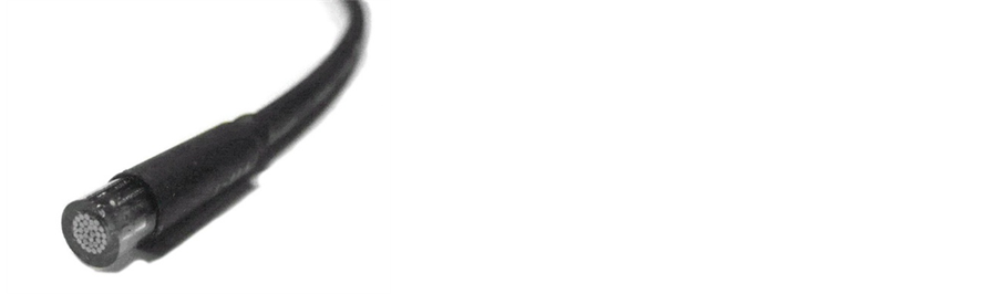
Figure 2. Optical fiber type “Sh4”.

Figure 3. Spectral characteristics of optical fiber.
plified and are fed to the inputs of analog-to-digital converter (ADC).
Analog part of the pyrometer is based on the low-noise precision operational amplifiers. The high-frequency noise reduction is performed by balanced of analog and digital lines, and the shielding of analog parts.
Fluctuations of ambient temperature cause additional error in IR radiometry [9] . Generally, reducing the influence of temperature background leads to a significant complexity of construction of radiometric meters that affect the portability of the device. The pyrometer uses compensation channel for optical fiber which compensate the influence of background temperature and so increase the measurement accuracy. This compensation channel is an optical fiber with closed input for object radiation, which located in the same conditions as the measurement channel, but does not transmit radiation of an object [3] . Thermal radiation of the main and compensation channels are received by optoelectronic converter module. Modulated by a mechanical modulator radiations from object and compensation are converted by pyroelectric sensors to voltages. Then they are amplified and fed to the analog-to-digital converter input. The signal received by the compensation channel is subtracted from the signal received by main channel. Figure 4 shows that the use of compensatory channel to reduce measurement error caused by temperature drift of fiber-optic system.
3. Control and Data Processing Module
Control and data processing module is based on the 16-bit microcontroller (MCU) MSP430. The main feature of this MCU is an asynchronously clocking of MCU’s periphery modules. It allows to enter in low-power mode with power consumption <1 uA and wakeup by the external interruption. This allows creating of portable device with long time of battery life. MCU controls the operation of such functional parts as temperature measurements, user interface, data processing, power management and wireless communication with PC. The digital filter and integrator provides the optimal filtering of signal and its integration with different time constant.
The built-in ADC is a 7-channel delta-sigma 16-bit ADC. The ADC input receives a signal of both channels which is amplified and filtered by a digital filter. The main input of ADC and the compensation input of ADC are grouped to synchronize the phases of input signal (Figure 5).
Generator of reference oscillations is an infrared optocoupler which is interrupted by modulation system. The optocoupler signal is passed through the Schmitt trigger and is fed to the MCU external interruption input. The signal from the generator is a reference signal for synchronous detection.
Using of the modulation system allows us to use methods of synchronous detection for the optimal allocation of signal in noise. Synchronous detection is the optimal method to receive signal over big noise and has a number of significant advantages over non-linear detection such as large dynamic range; high linearity of the amplitude characteristics which can distinguish the difference of sign brightness temperature of the object radiation and reference radiation.

Figure 4. The temperature of main channel (object temperature) (1) and temperature of compensation channel (reference temperature) (2).
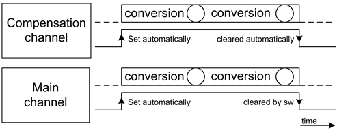
Figure 5. The process of analog-digital conversion channels is grouped.
USB-dongle for wireless communication in ISM frequency range based on ultra low power CC1000 transceiver was developed.
4. Processing Algorithms
Below, a software algorithm is presented. The software has been distributed among two main parts: foreground and background processes [17] . The foreground process starts with initialization of interruption vectors, an analog-to-digital converter, system timers, hardware interfaces (SPI, UART, I2C) and peripheral modules (Figure 6). Foreground process sets the gain of optoelectronic converter module, time constants, emissivity and the frequency modulation value to 12.5 Hz. At this frequency the sensitivity of the pyroelectric sensor is maximum.
Digital potentiometer in conjunction with operational amplifier provides variable gain of optoelectronic module, thus increasing of sensitivity for low-temperature measurements and reduces it for high-temperature measurements. Thereby it expands the range of measured temperatures.
Then foreground process initializes an optoelectronic module: generator of reference oscillation, amplifiers and pre-amplifiers, analog filters and pyroelectric sensors, enables interruption from the generator of reference oscillation.
The modulation subsystem is started and generates the reference oscillation in temperature measurement mode. This oscillation is configured as MCU external interrupt. So it is possible to determine the modulation phase (positive period (T+) or negative period (T−)) (Figure 7).
To carry out the correct conversion of the analog signal to digital form is necessary to determine the time at which sampling will be carried out analog signals. Fluctuations between the signal and the frame of reference oscillation fluctuations cause an additional error. This error is excluded by delay ΔT between the wavefront of the reference oscillation and the moment of synchronous detector start/stop. Thus, the reference oscillation is only a trigger for starting and stopping the software synchronous detector. Phase and frame duration of synchronous detector is chosen to minimize a measurement error. The value of shift is automatically setup by the synchronous detector during calibration process of the pyrometer.
Background process is started by ADC interruption at the end of data conversation (Figure 8). Background process handles analog-to-digital conversion, shifts the reference oscillation, starts/stops synchronous detector, and calculates modulation frequency. The main distinguishing feature of this pyrometer is that the quadratic value of the signal for each channel is used as synchronous accumulation. So synchronous detector module is formed root mean square (RMS) value for each measurement channels
 (1)
(1)
where N is a number of samples per half-cycle. This algorithm shows high stability and sensitivity of measurements in experiments. RMS value is written in the 16-bit third order array, which is stored in 48-bit registers of the processor, suitable for further mathematical evictions of large numbers. It is possible to reduce the load on the MCU during performing mathematical operations up to 30%.
Background process transfers control to the foreground process by setting the flags. The digital data implemented in the foreground process integrates data by the sliding window method. It is possible to choice the time constant in the range 80 mS to 5 sec in real time.
In the modulation pyrometers an output signal is proportional to the difference of 2 values. One of which is

Figure 6. Foreground process.

Figure 7. Analog to digital conversion and synchronous detection of signal.
proportional to the temperature of the object and another one is proportional to the temperature of reference emitter. Usually, a reference radiation is the radiation emitted by mechanical modulator with temperature . The temperature sensor is installed in the immediate proximity of the rotating modulator. The output signal from the synchronous detector enters to the temperature calculation module, in which the ADC data values are converted to temperature using the calibration curve.
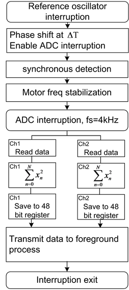
Figure 8. Background process.
 (2)
(2)
The algorithm of the wireless communication channel is built on the principle of master-slave model. The master device (PC) polls all of its customers (pyrometers, other sensors). This allows reducing computational load of pyrometer’s MCU and improving power management of the device because the wireless data are transferred only in time of master request. The transceiver goes to sleep with ultra low power consumption in idle mode.
Figure 9 shows the message format for communication between pyrometer and PC. Communication protocol is binary and synchronous. Packet length is limited by 14 bytes.
ADDRESS—this field contains the pyrometer address or an address of other sensors or devices. Due to this it is possible to create radiometric automated monitoring system.
COMMAND—command to execute.
LENGTH OF DATA DATA—requested data (e.g. object’s temperature, temperature of the compensation channel, the modulation frequency).
STATUS—the execution status of the command.
CRC—cyclic redundancy check value. This value is calculated by sender and verified by package receiver. Using of CRC eliminates communication errors thereby increasing the reliability of data transmission. As a criterion reliability of data transfer was chosen lose packets probability value 10−3 means of a reliable data transfer for 16 minutes.
Figure 10 shows the sequence diagram of data transfer between PC and pyrometer for “Get info” command (command “Get info” is intended to survey the pyrometer parameters such as object temperature, the temperature of compensation channel, the frequency modulation and etc.).
Using of wireless devices for measuring process can increase the amount of collected information for more effective management. Using a computer and specially designed software can perform the necessary data processing (e.g. digital filtering, the calculation of the dispersion of measurement results), show results on the chart in real time and saving results in a file.
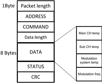
Figure 9. Package format.
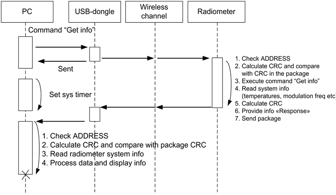
Figure 10. Sequence diagram.
5. Summary
Thus, the infrared pyrometer developed provides high precision, sensitivity and stability of temperature measurements, high surface resolution, eliminating the influence of the external background, the possibility of measuring temperature in difficult-to-access places, portability, wireless remote monitoring of an object temperature.
The pyrometer can be used for biomedical research, monitoring temperatures in remote places.
Acknowledgements
This work was supported by the Government of the Russian Federation, Grant No. 11G34.31.0066.
References
- Tarasov, V.V. and Yakushenkov, Yu.G. (2004) Staring-Type Infrared Systems. Logos, Moscow.
- Kistemaker, J.A., Den Hartog, E.A. and Daanen, H.A.M. (2006) Reliability of an Infrared Forehead Skin Thermometer for Core Temperature Measurements. Journal of Medical Engineering & Technology, 30, 252-256. http://dx.doi.org/10.1080/03091900600711381
- Kocoglu, H., Goksu, S. and Isik, M. (2002) Infrared Tympanic Thermometer Can Accurately Measure the Body Temperature in Children in an Emergency Room Setting. International Journal of Pediatric Otorhinolaryngology, 65, 39- 43. http://dx.doi.org/10.1016/S0165-5876(02)00129-5
- Rosenthal, H.M. and Leslie, A. (2006) Measuring Temperature of NICU Patients—A Comparison of Three Devices. Journal of Neonatal Nursing, 12, 125-129. http://dx.doi.org/10.1016/j.jnn.2006.05.007
- Dodd, S.R., Lancaster, G.A. and Craig, J.V. (2006) In a Systematic Review, Infrared Ear Thermometry for Fever Diagnosis in Children Finds Poor Sensitivity. Journal of Clinical Epidemiology, 59, 257-354. http://dx.doi.org/10.1016/j.jclinepi.2005.10.004
- Myasoedov, Yu.M. (2010) The Use of Infrared Thermometry to Determine Body Temperature of Laboratory Rodents. Journal of Veterinary Biology, 2, 34-37.
- Afanasjev, A.V., Orlov, I.Ya. and Nikiforov, I.A. (2008) Infrared Pyrometer for Biomedical Research. Instruments and Experimental Techniques, 4, 164-166.
- Sayre, E.K., Kelechi, T.J. and Neal, D. (2007) Sudden Increase in Skin Temperature Predicts Venous Ulcers: A Case Study. Journal of Vascular Nursing, 25, 46-50. http://dx.doi.org/10.1016/j.jvn.2007.06.002
- McCluney, W.R. (1994) Introduction to Radiometry and Photometry. Artech Print on Demand, Norwood.
- Afanasjev, A.V., Orlov, I.Ya. and Nikiforov, I.A. (2011) High-Precision Pyrometer of Infrared Radiation. Sensors and Systems, 72, 888-892.
- Orlov, I.Ya., Afanasjev, A.V., Nikiforov, I.A., Odnosevtsev, V.A. and Afanasjev, O.A. (2011) Pyrometer. Patent RU2437068.
- Orlov, I.Ya. and Khrulev, A.Ye. (2002) Some Possibilities for Reducing the Error Due to Heating of the Iris of the Optical Sensor with Infrared Radiometry. Sensors and Systems, 9, 36-40.
- Shirobokov, A.M., Shchupak, Yu.A. and Chukin, V.M. (2002) Processing of Thermal Images Obtained by MultiSpectral Imager Therma-2. News of Higher Educational Institutions. Instrumentation, 45, 17.
- Tkachenko, Yu.A. (2008) Infrared Pyrometer. Patent RU74282.
- Bykova, S.V., Dozhdikov, V.S., Golyshev, V.D., Gonik, M.A., Petrov, V.A., Senchenko, V.N. and Tsvetovski, V.B. (2002) The Study of Supercooling of the Interface with an Optical Pyrometer of High Resolution—Chemistry and Computational Simulation. Butlerov Message, 10, 117-122.
- Kolesov, S.N. and Golovanova, M.V. (2008) Infrared Radiometry. Begemot Ltd., N. Novgorod, 80.
- Orlov, I.Ya., Afanasjev, A.V. and Nikiforov, I.A. (2009) Data Processing Algorithms in the Modulation Infrared Pyrometer. Proceedings of the VIII International Scientific-Technical Conference Emerging Technologies in the Means of Information Transfer, Vladimir, 2, 60-64.