Wireless Engineering and Technology
Vol.3 No.1(2012), Article ID:16936,11 pages DOI:10.4236/wet.2012.31001
A Comprehensive Parametric Study of Planar Inverted-F Antenna
![]()
1Department of Electrical, Electronics and Telecommunication Engineering, University of Engineering & Technology (Lahore), Faisalabad Campus, Faisalabad, Pakistan; 2Department of Electrical Engineering & Electronics, University of Liverpool, Liverpool, UK; 3Department of Telecommunication Engineering, GC University, Faisalabad, Pakistan.
Email: chattha43@hotmail.com, Yi.Huang@liverpool.ac.uk
Received December 14th, 2011; revised December 31st, 2011; accepted January 10th, 2012
Keywords: Antennas; Planar Antennas; PIFA; Impedance Bandwidth and Empirical Equation
ABSTRACT
This paper presents a comprehensive numerical and experimental study of Planar Inverted-F Antennas (PIFA) involving all the parameters which may affect the characteristics of PIFA. It is found that PIFA characteristics are affected by a number of parameters including the dimensions of the ground plane, length, width, height and position of the top plate, positions and widths of shorting pin/plate and feed pin/plate. It is also found that the width of feed plate plays an important role in broadening the antenna bandwidth. It is shown that a fractional impedance bandwidth up to 65% can be obtained using an optimized design. Furthermore, a new empirical formula is introduced for the estimation of the central operational frequency of PIFA. These results are very useful for aiding PIFA design in practical applications.
1. Introduction
The Planar Inverted-F Antenna (PIFA) can be viewed as evolved from a quarter-wavelength monopole antenna and is now widely used in mobile and portable radio applications due to its many attractive attributes such as simple design, lightweight, low-cost, low-profile, conformal nature and reliable performance [1-4]. Many antenna types for portable applications are extensions of PIFA antenna [5-7], which is considered as one of the strongest candidates for multiple-input multiple-output (MIMO) systems [8,9].
It is well-known that, for a monopole antenna, the desired length is a quarter-wavelength as it is resonant in this case. Using the same analogy, the following empirical equation was proposed for finding the resonant frequency of PIFA [3,10,11].
 (1)
(1)
where c is the speed of light/radio wave, L and W are the length and width of the radiating top plate of the PIFA and f0 is the resonant/operating frequency. This equation means that the sum of the length and width of the top plate should be a quarter-wavelength. However, it is actually a very rough approximation and does not cover all the parameters which significantly affect the resonant frequency of PIFA as it will be shown later. It can hardly be used to guide the design in practice, thus a more accurate, robust and comprehensive design equation is required. In [12], an effort was made to incorporate some parameters of the antenna (other than W and L) in the evaluation of resonant frequency. In particular, the width of the shorting plate (Ws) was incorporated with two degrees of freedom. The formula is given as follows for Ws ≥ 20 mm:
 (2)
(2)
where DL = 2.741, k1 = 0.0188 and k2 = 0.0767. Note that this equation has a restricted application due to the condition on Ws. This equation also does not cover all the significant parameters of PIFA which affect the resonant frequency.
In the case of a wire Inverted-F Antenna (IFA), design curves are available for a given resonant frequency and impedance bandwidth through which IFA can be easily designed [13]. However, no such design curves exist for the PIFA. If similar design curves can be made available, it would be a very useful guideline for people to design the PIFA antenna at a given resonant frequency. There are many papers which describe the variations in the characteristics of PIFA due to changes of its parameters [12,14-23]. Specifically the effects of the ground plane and the height of the top plate are discussed in [18-22] and [23] respectively. However there has not been presented a comprehensive study involving all the parameters of PIFA on the effects of parameter changes to the resonant frequency, impedance bandwidth and radiation Pattern.
This paper presents a comprehensive experimental and numerical investigation on PIFA that includes all the parameters that may affect its characteristics. The effects on the characteristics of PIFA due to changes in the dimensions of ground plane, the position of PIFA on ground plane, the length, width, and height of the top radiating plate, and the distance of the shorting plate from the edge of top plate are presented. Similarly, the effects of changing the widths of the feed plate and the shorting plate, and the feeding positions are also discussed in this paper. At the end, a new empirical equation is proposed that describes the behavior of the PIFA antenna resonance; a very useful tool to predict the resonant frequency of PIFA. This new equation is compared with the two equations presented previously, with respect to its accuracy. The information given in this paper should be very helpful for antenna engineers to design the PIFA antenna for a given resonant frequency and impedance bandwidth.
2. Antenna Configuration
The configuration of the PIFA used for this study is shown in Figure 1. The radiating top plate has dimensions L × W and the ground plane dimensions are Lg × Wg as shown in Figure 1. The PCB dielectric material used above the rectangular ground plane is FR-4 having a thickness t = 1.5 mm and a relative permittivity εr = 4.4. The space between the ground and the top plate with height h is empty for this investigation although supporting materials may be used in practice. The shorting plate has dimension Ws × (h + t) and the feed plate has dimensions Wf × h. The horizontal and vertical distances of the feed plate from the side and upper edges of top plate are Lb and Lu respectively. The distance between the shorting plate and the side edge of the top plate is Ls. The vertical and horizontal distances of the PIFA structure from the ground plane edges are Lz and X respectively, as shown in Figure 1(b). The ground plane is placed in x-y plane and height of antenna is along z-axis.
3. Numerical and Experimental Study
The procedure adopted for this study is that only one parameter is changed at a time to observe its effects on the PIFA characteristics while all other parameters are held constant. Different sets of parameters are taken for study to cover a wide range of values and also at different resonant frequencies. The operational frequency ranges from 0.5 GHz to 3 GHz to cover most popular mobile frequency bands. Most of the simulated and measured results are very similar, but some results are different. The major courses for their differences are 1)
 (a)
(a) (b)
(b)
Figure 1. (a) Planar inverted-F antenna under study; (b) Geo-metry of PIFA structure.
the cables: which are not included in the simulation but presented in the measurements; 2) the connector: which is also not considered in the simulation; 3) The inaccuracy of exact parameters in manufacturing the PIFAs as they are made manually in the lab.
The numerical simulation software is Ansoft’s High Frequency Structure Simulator (HFSS) which is based on the finite element method, very flexible and suitable for this study. The simulation results were compared against measurements, therefore several PIFA antennas were fabricated and tested, some of them are shown in Figure 2.
For convenience, a reference PIFA antenna is chosen with the following parameters (13 in total): 1) Width of top plate W = 37.5 mm, 2) Length of top plate L = 18

Figure 2. PIFA used for experiments.
mm, 3) Height of PIFA h = 12 mm, 4) Width of feed plate Wf = 10 mm, 5) Width of shorting plate Ws = 5 mm, 6) Distance between feed and shorting plates Lb = 15 mm, 7) Vertical distance of PIFA from the upper edge of the ground plane Lz = 0 mm, 8) Horizontal distance of PIFA from the side edge of the ground plane X = 0 mm, 9) Distance of shorting plate from the side edge of top plate Ls = 0 mm, 10) Length of ground plane Lg = 75 mm, 11) Width of ground plane Wg = 65 mm, 12) Vertical distance of feed plate from the upper edge of top plate Lu = 0 mm and 13) Thickness of substrate t = 1.5 mm.
3.1. Ground Plane Effects
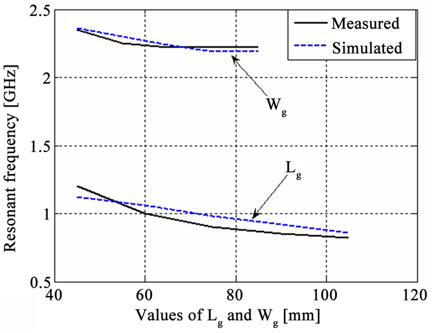
The width of ground plane Wg is varied from 45 mm to 85 mm and all other parameters are same as reference antenna. Similarly, the length of the ground plane Lg is varied from 45 mm to 105 mm and Wg = 75 mm, W = 75 mm, L = 30 mm, h = 30 mm, Wf = 24 mm, Ws = 1 mm, Lb = 21 mm while all other parameters are same as the reference antenna. The simulated and experimental results are shown in Figure 3 which shows the effects of the width and length of the ground plane on the resonant frequency, fractional bandwidth and radiation pattern. The increase in Lg or Wg decreases the resonant frequency but increases the fractional bandwidth. The resonant frequency is not very sensitive to the dimensions of the ground plane—this could be due to the fact that the antenna dimension is the dominant factor for radiation.
After extensive simulations, it is also observed that minimum ground plane length plus width required for maximum impedance bandwidth is λ/2.
3.2. Position of PIFA on the Ground Plane
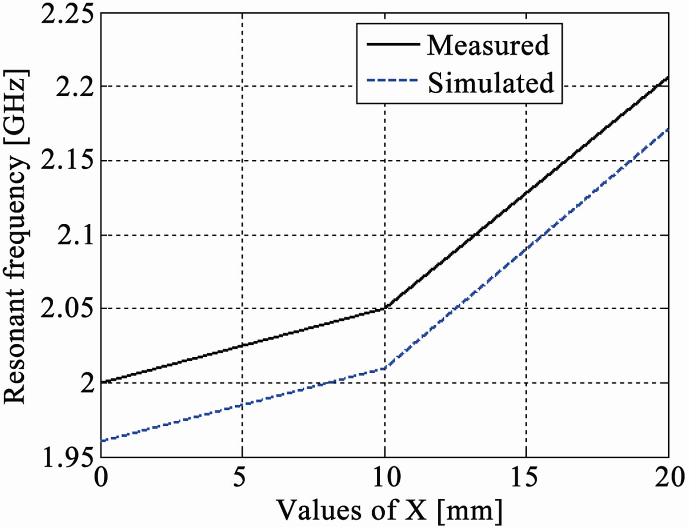
The changes are made in the horizontal distance X and vertical distance Lz of the PIFA from the edges of the round plane to see their effects on the characteristics of the PIFA. The value of X is changed from 0 mm to 20 mm and the value of Lz is changed from 0 mm to 50 mm while all other parameters are same as the reference antenna. The simulated and experimental results are shown in Figure 4. The results show that variations in X and Lz change the resonant frequency and impedance bandwidth,
 (a)
(a)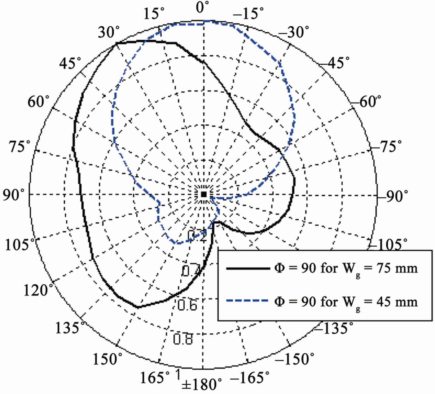 (b)
(b) (c)
(c)
Figure 3. (a) Ground plane width Wg and ground plane length Lg (mm) vs resonant frequency (GHz); (b) Measured radiation pattern in elevation (Φ = 90˚) plane for different Wg; (c) Ground plane length Lg (mm) vs fractional bandwidth.
and also have significant effects on the radiation pattern. The increase in either X or Lz increases the resonant frequency and decreases the fractional bandwidth.
It can be concluded that the placement of PIFA on the ground plane significantly affects the characteristics of the PIFA: the antenna should be placed near the edges (Lz = 0, X = 0) of the ground plane to obtain the maximum impedance bandwidth.
 (a)
(a)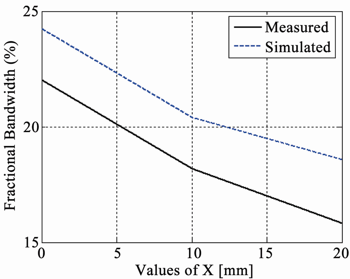 (b)
(b)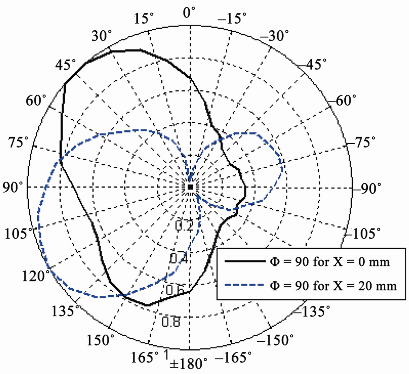 (c)
(c)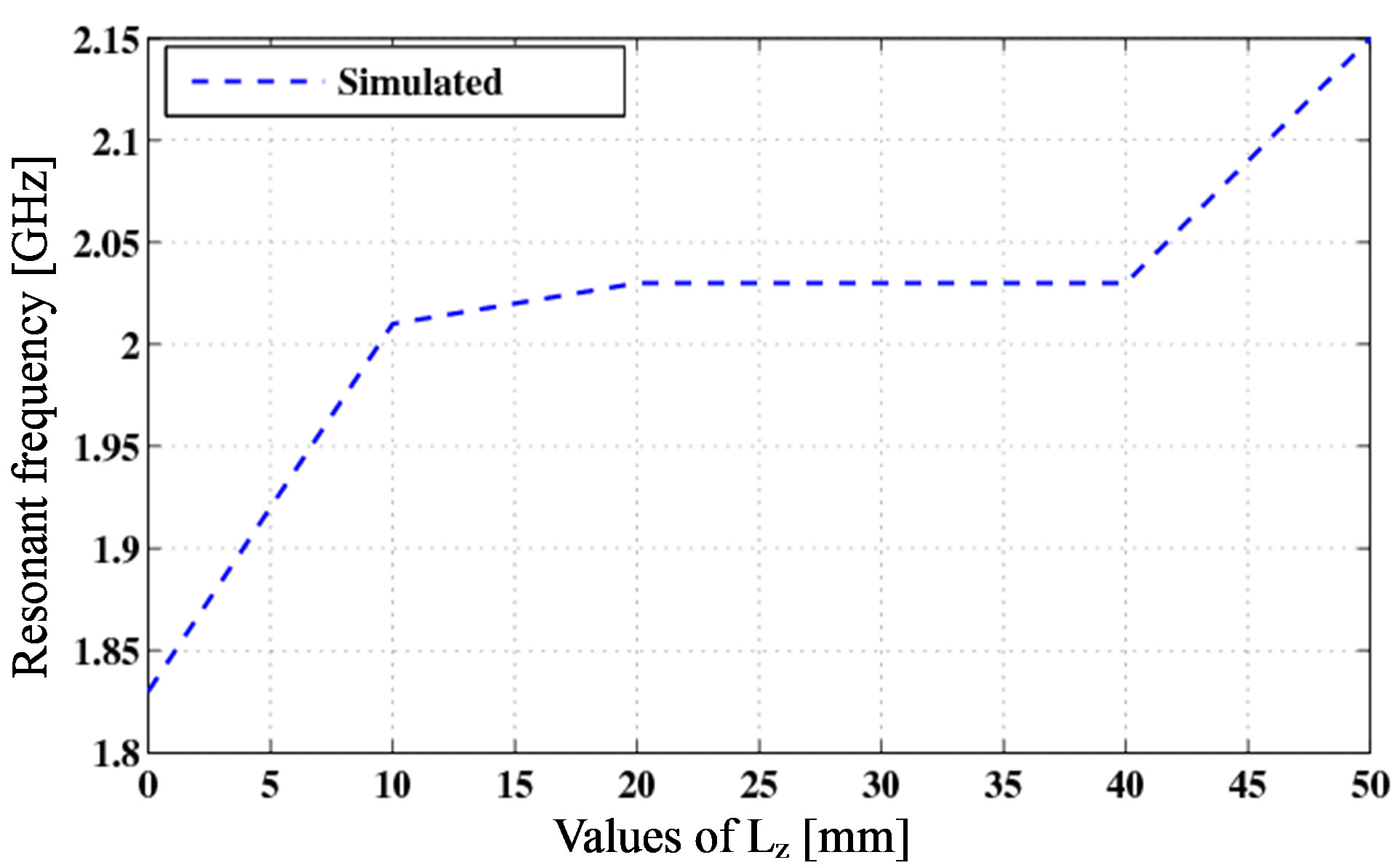 (d)
(d)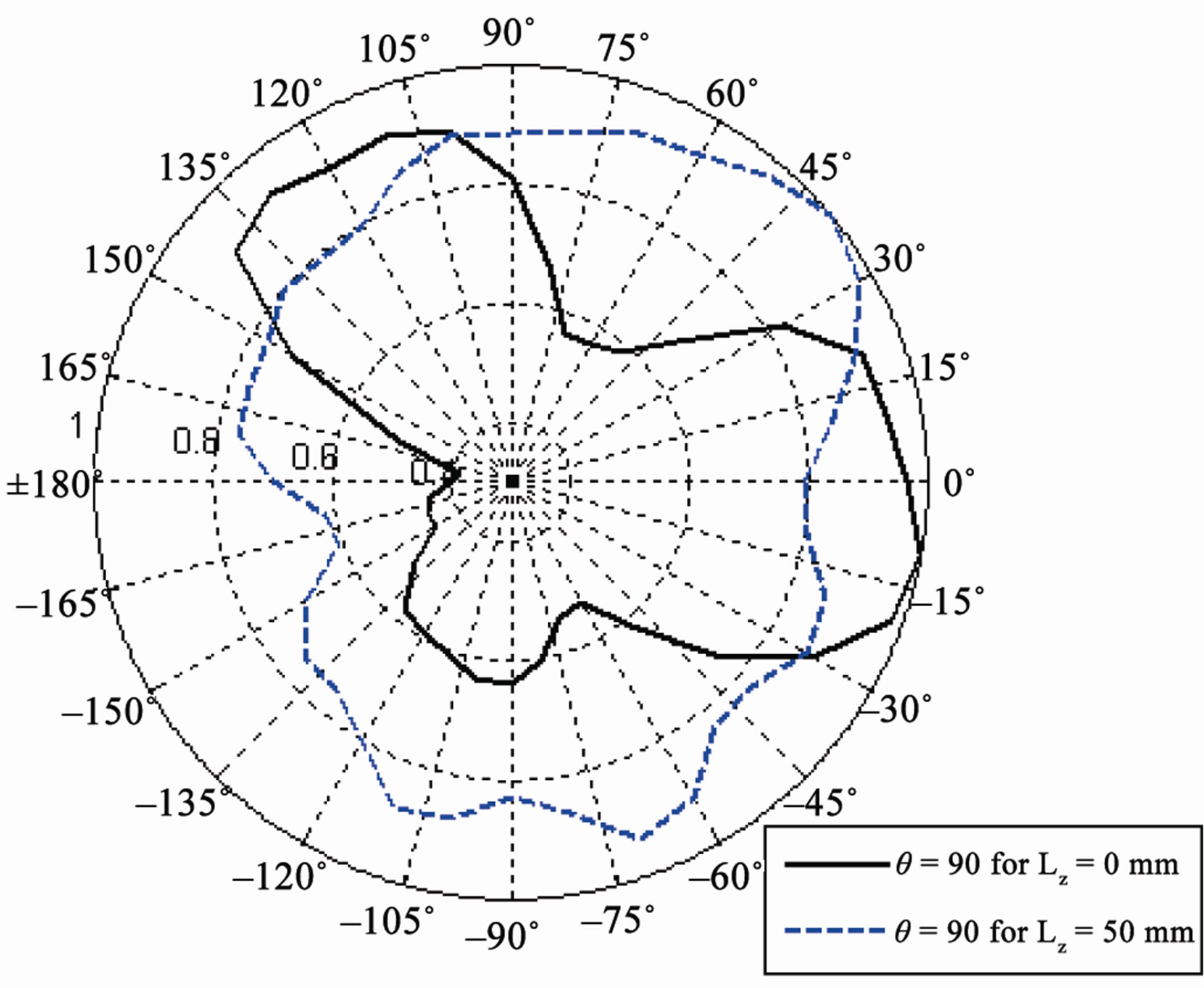 (e)
(e)
Figure 4. (a) Values of X (mm) vs resonant frequency (GHz); (b) Values of X (mm) vs fractional bandwidth; (c) Measured radiation pattern in elevation (Φ = 90˚) plane for different X; (d) Values of Lz (mm) vs resonant frequency (GHz); (e) Simulated radiation patterns in azimuth (θ = 90˚) plane for different Lz.
3.3. Dimensions of Top Plate
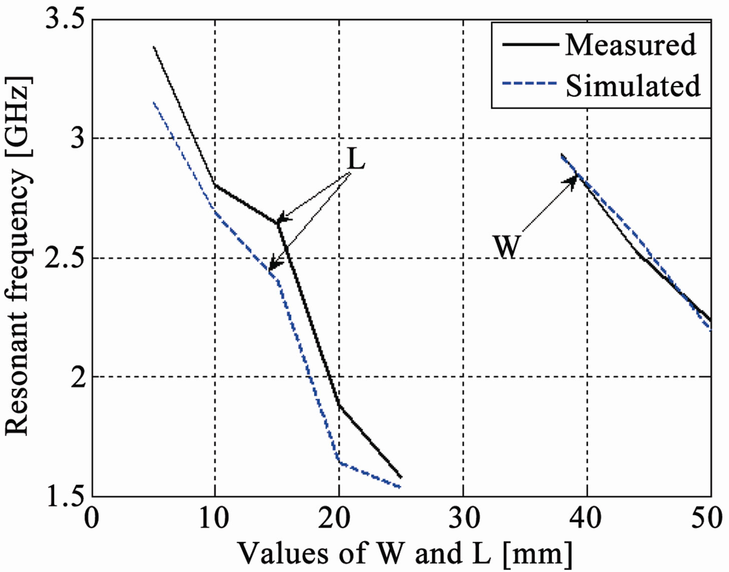
Now the changes are made in the length and the width of the rectangular top plate and their effects are observed on the characteristics of the PIFA. The width of the top plate is varied from 38 mm to 50 mm and length of the top plate is changed from 5 mm to 25 mm and Lg = 60 mmWg = 50 mm, h = 14 mm Wf = 15 mm, Ws = 2 mm, Lb = 10 mm, while other parameters are same as the reference antenna. The simulated and experimental results are shown in Figure 5. It is apparent that the increase in the length or width of the top plate decreases the resonant frequency and affects the impedance bandwidth. As a
 (a)
(a) (b)
(b)
Figure 5. (a) Values of W and L (mm) vs resonant frequency (GHz); (b) Measured radiation patterns in elevation (Φ = 0˚) plane for different L.
PIFA is a quarter-wavelength antenna, increasing either the length or width of the top plate will result in the decrease of the resonant frequency. Small changes in length and width do not have a significant effect on the radiation pattern but as we know from the theory of characteristic modes, the radiation pattern is basically dependent on size and shape of top plate [24]. If the shape of the element is varied, the resonant frequency and the radiating properties of the modes will change.
It can also be concluded that the greater the size of the top plate of the PIFA, the more directive the radiation pattern, i.e. the directivity will be higher as shown in Figure 5(b).
3.4. Height of PIFA
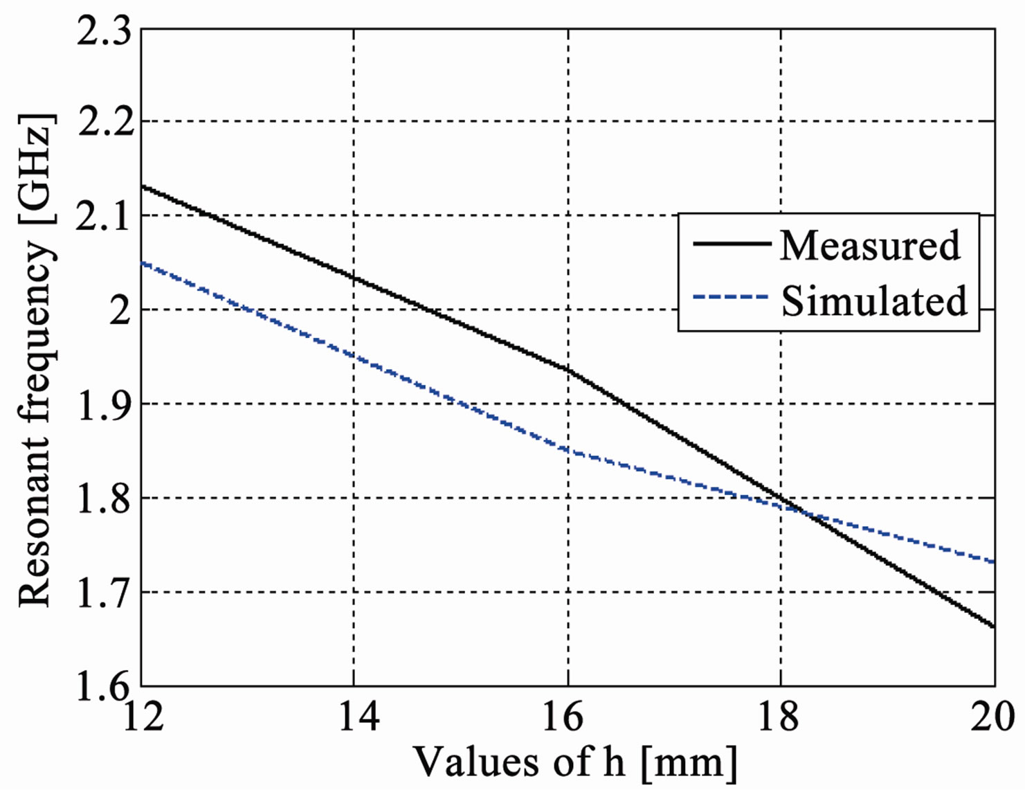
The height of the top plate h is now varied from 12 mm to 20 mm to observe its effects while all other parameters are same as the reference antenna. The simulated and experimental results are shown in Figure 6. The results show that the increase in height decreases the resonant frequency and increases the fractional impedance bandwidth, but does not have any significant effect on the ra-
 (a)
(a)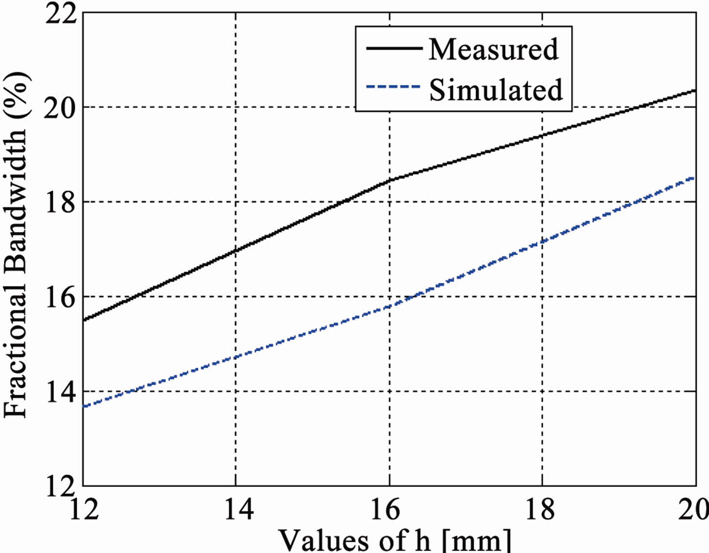 (b)
(b)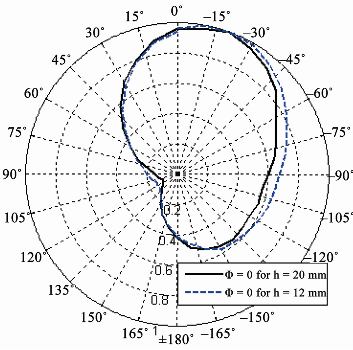 (c)
(c)
Figure 6. (a) Values of h (mm) vs resonant frequency (GHz); (b) Values of h (mm) vs fractional bandwidth; (c) Measured radiation patterns in elevation (Φ = 0˚) plane for different values of h.
diation pattern. The decrease in the resonant frequency is obvious as h increases, the wavelength increases. The height of PIFA can be increased to enhance the impedance bandwidth but a small height of the top plate is preferred in practice as the antenna has to be small enough to fit it in the chassis of small terminal devices. So the height of antenna cannot normally be used to enhance the impedance bandwidth in applications.
3.5. Distance of the Shorting Plate from the Edge of Top Plate
The distance of shorting plate from the side edge of the top plate Ls is varied from 0 mm to 15 mm to observe its effects on the characteristics of PIFA and Wg = 75 mm, L = 20 mm, W = 50 mm, Lb = 10 mm, while all other parameters are unchanged and simulated and experimental results are shown in Figure 7. The results show that the increase in Ls increases the resonant frequency and changes the fractional impedance bandwidth but has little effect on the radiation pattern.
3.6. Position of Feeding Configuration under the Top Plate
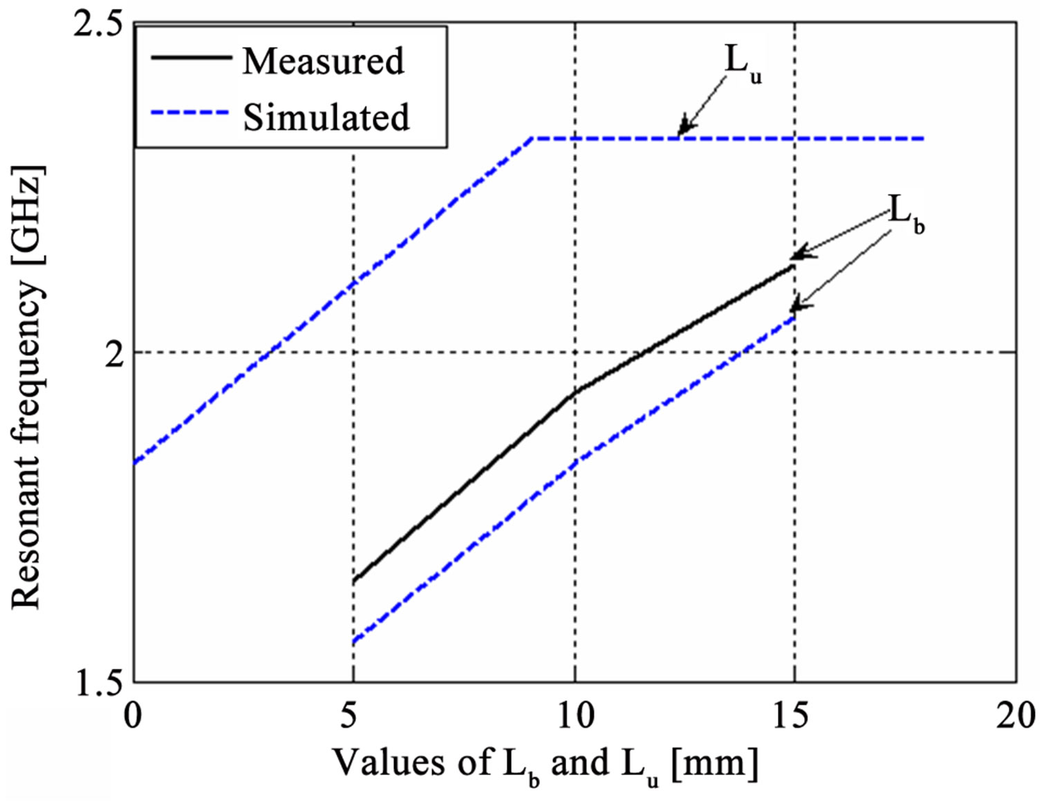
The position of the feeding configuration is investigated by altering the values of horizontal distance Lb from 5 mm to 15 mm and vertical distance Lu from 0 mm to 18 mm to observe their effects on the PIFA characteristics while other parameters are the same as the reference antenna. The simulated and experimental results are shown in Figure 8 which shows that the changes of feeding position under the top plate significantly affect the resonant frequency, impedance bandwidth and radiation pattern. The increase in the horizontal distance between the feeding and shorting plates increases the resonant frequency. Similarly, the increase in the distance between the feed and the upper edge of top plate increases the resonant frequency. As we know from the theory of characteristics modes that any conducting surface may have a number of modes, which can be excited by selecting
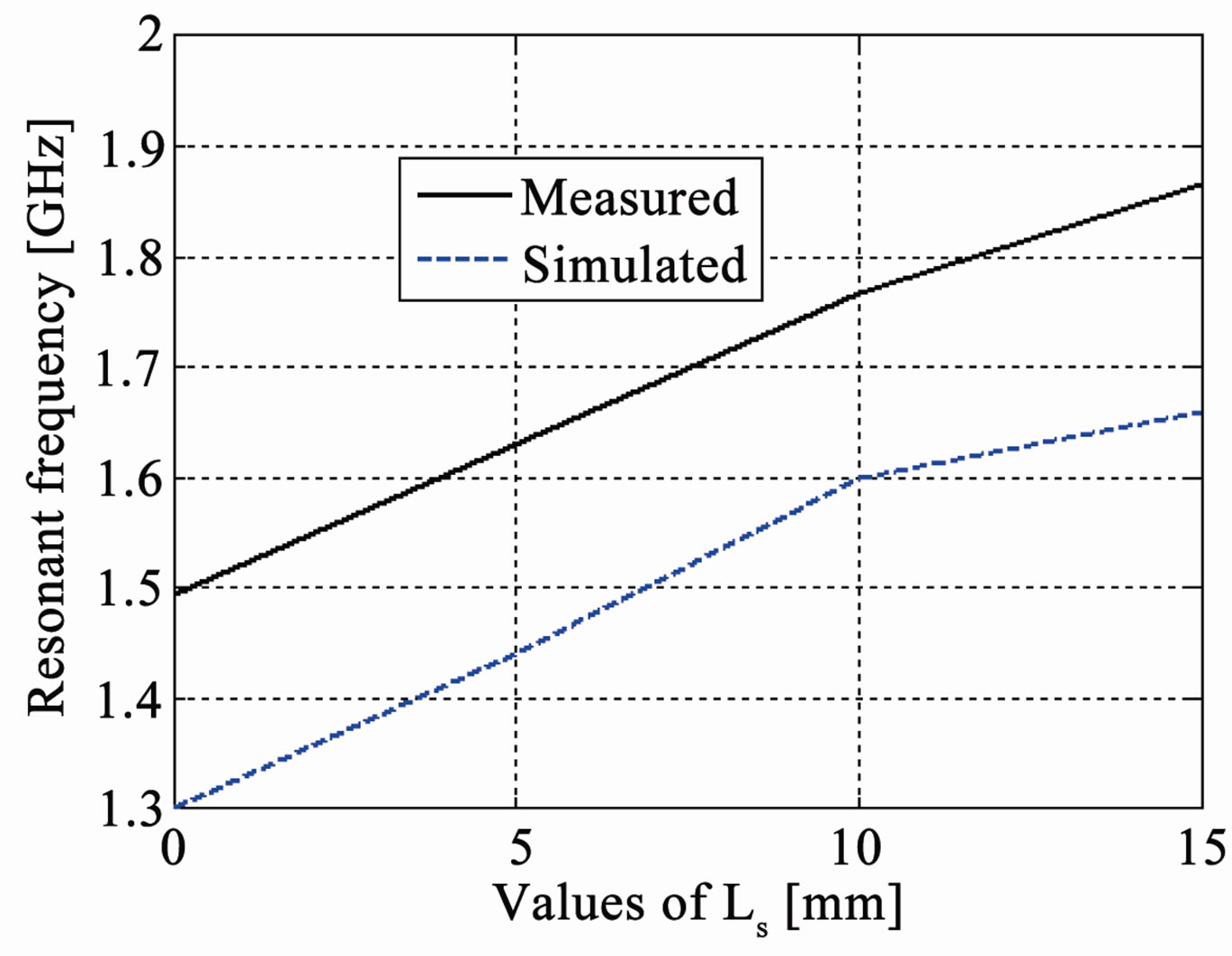
Figure 7. Values of Ls (mm) vs resonant frequency (GHz).
 (a)
(a)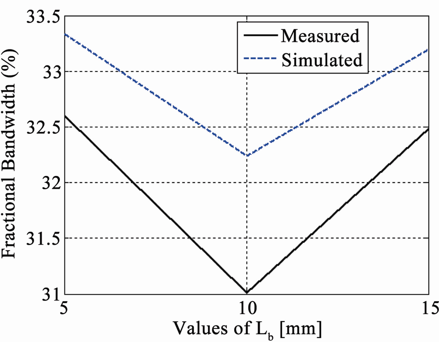 (b)
(b)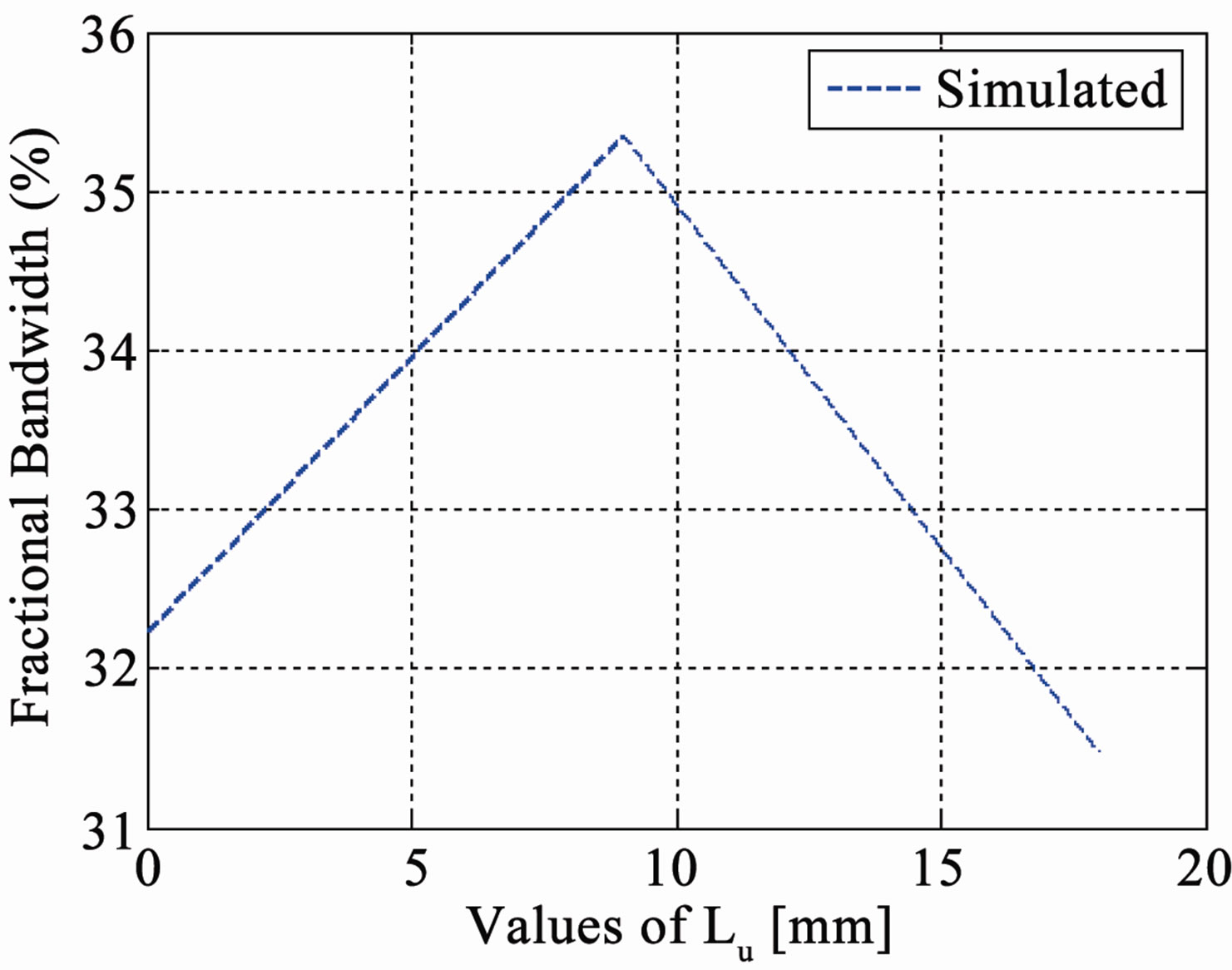 (c)
(c)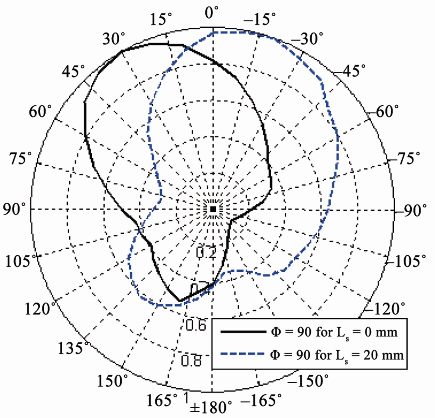 (d)
(d)
Figure 8. (a) Values of Lb and Lu (mm) vs resonant frequency (GHz); (b) Values of Lb (mm) vs fractional bandwidth; (c) Values of Lu (mm) vs fractional bandwidth; (d) Simulated radiation pattern in elevation (Φ = 90˚) plane for different Lu.
suitable positions of the feeding configuration, so when the feeding position is changed under the top plate, a different mode or a number of modes may be excited which change the resonant frequency, impedance bandwidth and radiation pattern [24]. Therefore the position of feed with respect to the shorting plate is very decisive in order to get the desired resonant frequency and high impedance bandwidth.
3.7. Width of Shorting Plate
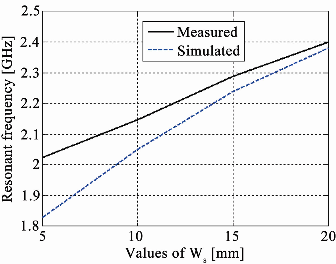
The width of shorting plate is varied from 1 mm to 20 mm while other parameters remain unchanged; the simulated and experimental results are shown in Figure 9. It can be seen that the variation in the width of shorting plate changes the resonant frequency and impedance bandwidth, but does not have any significant effect on the radiation pattern. The increase in the width of the shorting plate increases the resonant frequency and can cause an increase in fractional bandwidth. As we increase the shorting plate width, it causes an impedance mismatch that is why bandwidth becomes very narrow when Ws = 20 mm as shown in Figure 9(b). So if we want to increase the width of shorting plate, the feed position needs to be adjusted every time to get impedance matching [15].
3.8. Width of Feed Plate
The feed plate width is changed from 6 mm to 14 mm and Lg = 60 mm, Wg = 50 mm, W = 50 mm, L = 24 mm, h = 14 mm, Ws = 2 mm Lb = 24 mm, while all other parameters are the same as the reference antenna and simulated and experimental results are shown in Figure 10. It shows that like the width of shorting plate, the width of feed plate changes the resonant frequency and impedance bandwidth and does not have any significant effect on the radiation pattern. The increase in the width of feed plate increases the resonant frequency and significantly increases the fractional impedance bandwidth: 65% fractional bandwidth can be achieved by changing the widths of feed and shorting plates as shown in Figure 10(e)— this is very similar to the technique used to broaden the bandwidth of a dipole by making it “fat”. This finding is significant since this technique can make the PIFA very broadband. More information on this can be seen in our paper [25]. So the width of feed plate can be used to increase the impedance bandwidth of PIFA but it is limited by the increase of resonant frequency which needs to be adjusted by increasing other parameters like the length or width of the top plate which will decrease the resonant frequency.
4. Empirical Equation for PIFA
Based on our comprehensive parametric study, a large
 (a)
(a)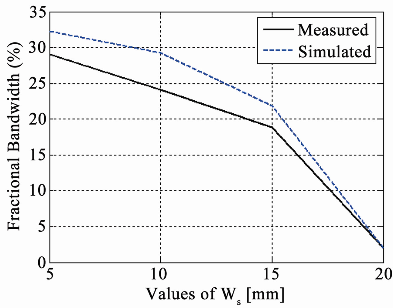 (b)
(b)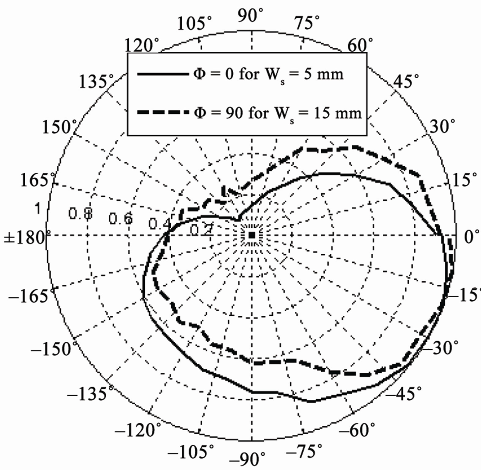 (c)
(c)
Figure 9. (a) Values of Ws (mm) vs resonant frequency (GHz); (b) Values of Ws (mm) vs fractional bandwidth; (c) Measured radiation pattern Eθ in elevation (Φ = 0˚) plane for different Ws.
database of different set of parameters using different ground plane dimensions is created and a new empirical equation is derived to find the centre frequency by using the function “nlinfit” (Nonlinear least-squares data fitting by the Gauss-Newton method) of MATLAB, taking into account all those parameters which significantly affect the value of the resonant frequency as seen in Figures 3- 10. These parameters are length, width and height of the top plate, widths of shorting and feed plates, and loca-
 (a)
(a)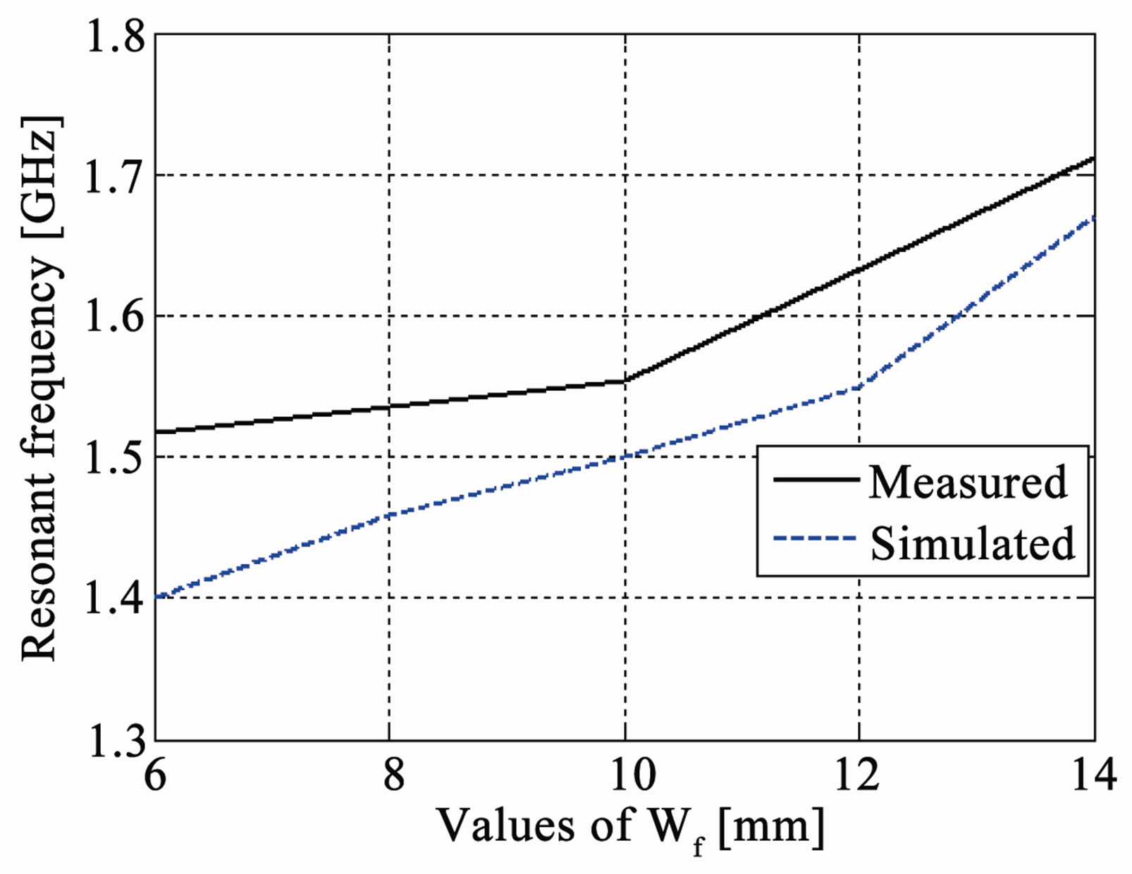 (b)
(b) (c)
(c)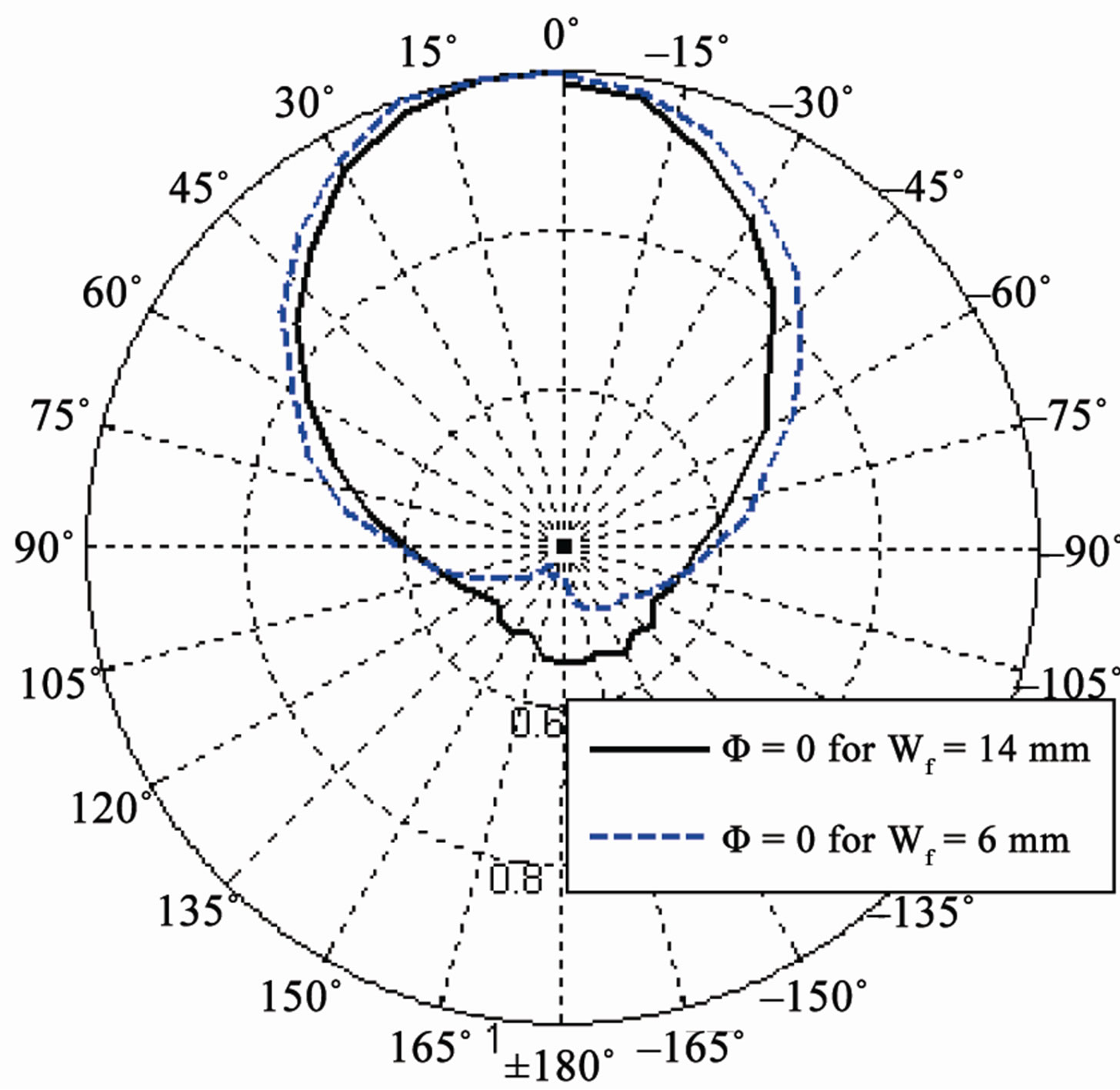 (d)
(d)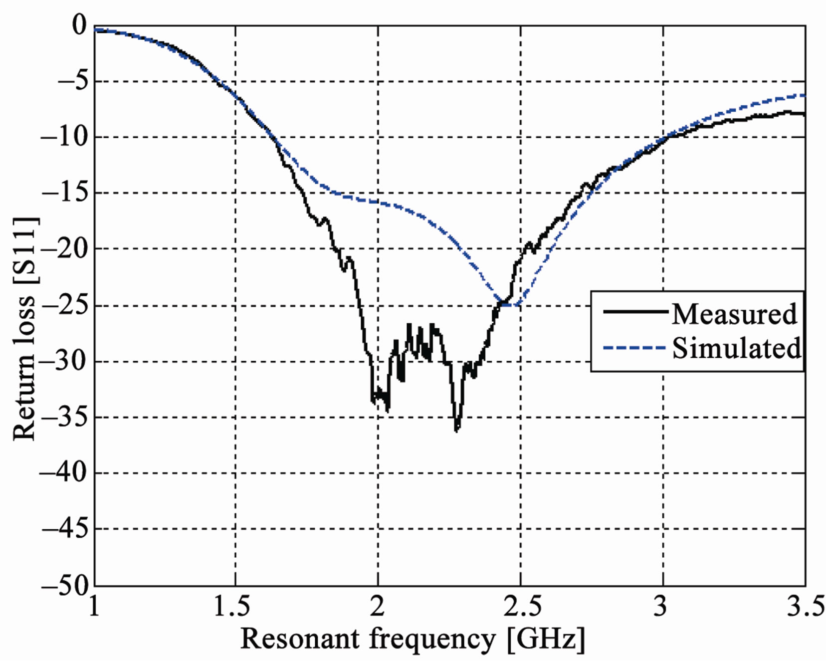 (e)
(e)
Figure 10. (a) Measured reflection coefficients for different values of Wf; (b) Values of Wf (mm) vs resonant frequency (GHz); (c) Values of Wf (mm) vs fractional bandwidth; (d) Measured radiation pattern in elevation (Φ = 0˚) plane for different Wf; (e) Reflection coefficient (S11) in dB vs frequency in GHz.
tions of shorting plate and feeding configuration under the top plate. Only horizontal distances of locations of shorting and feed plates are chosen. The vertical distances of feed and shorting plates from the edge of top plate are neglected to make the equation simple and also because their role is found not as significant as compared to the horizontal distances. The new proposed equation is therefore obtained as follows.
 (3)
(3)
where W, L and h are the width, length and height of the top plate respectively. Wf and Ws are the widths of feed and shorting plates whereas Lb is the horizontal distance between these plates and Ls is the distance of shorting plate from side edge of the top plate.
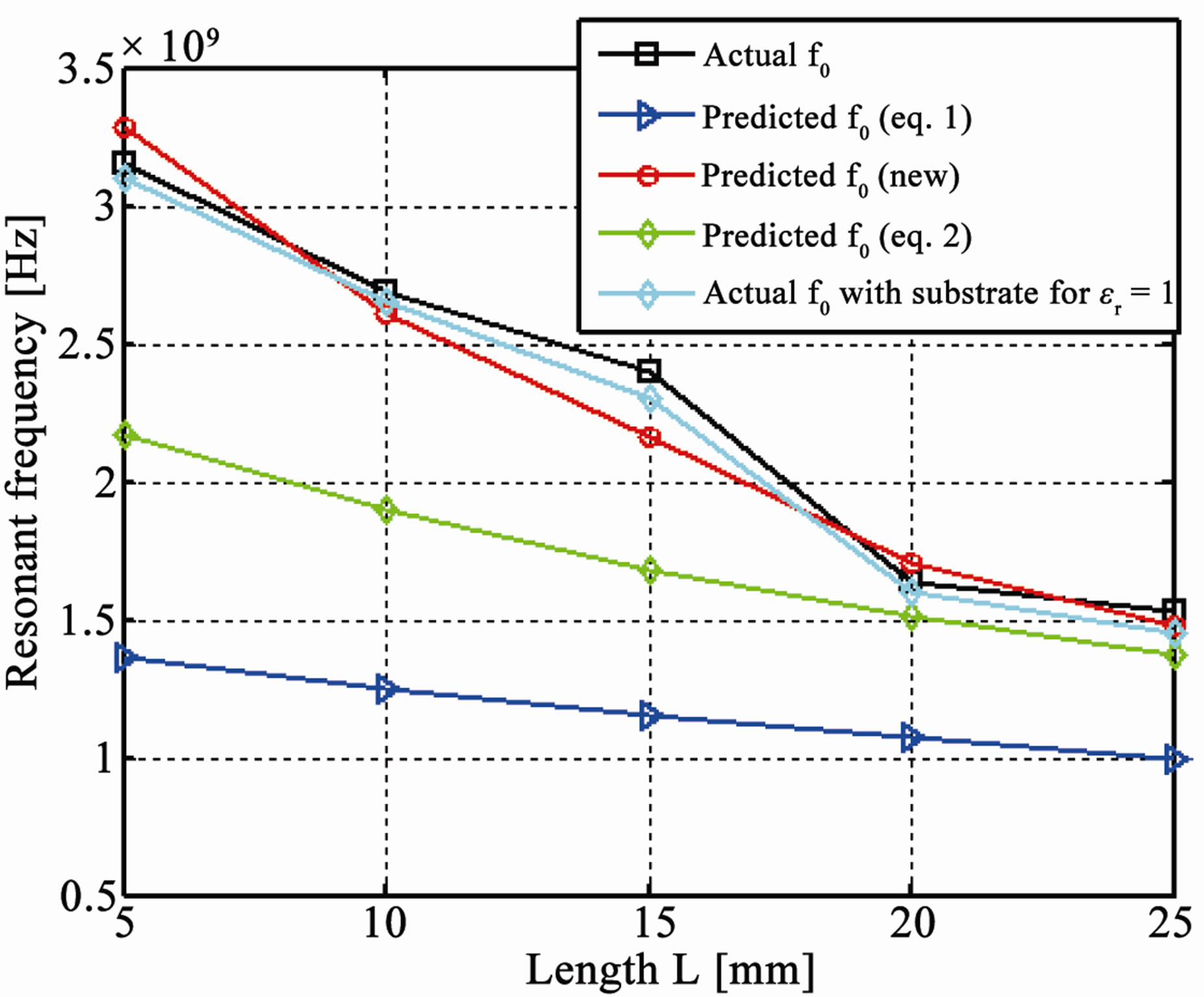
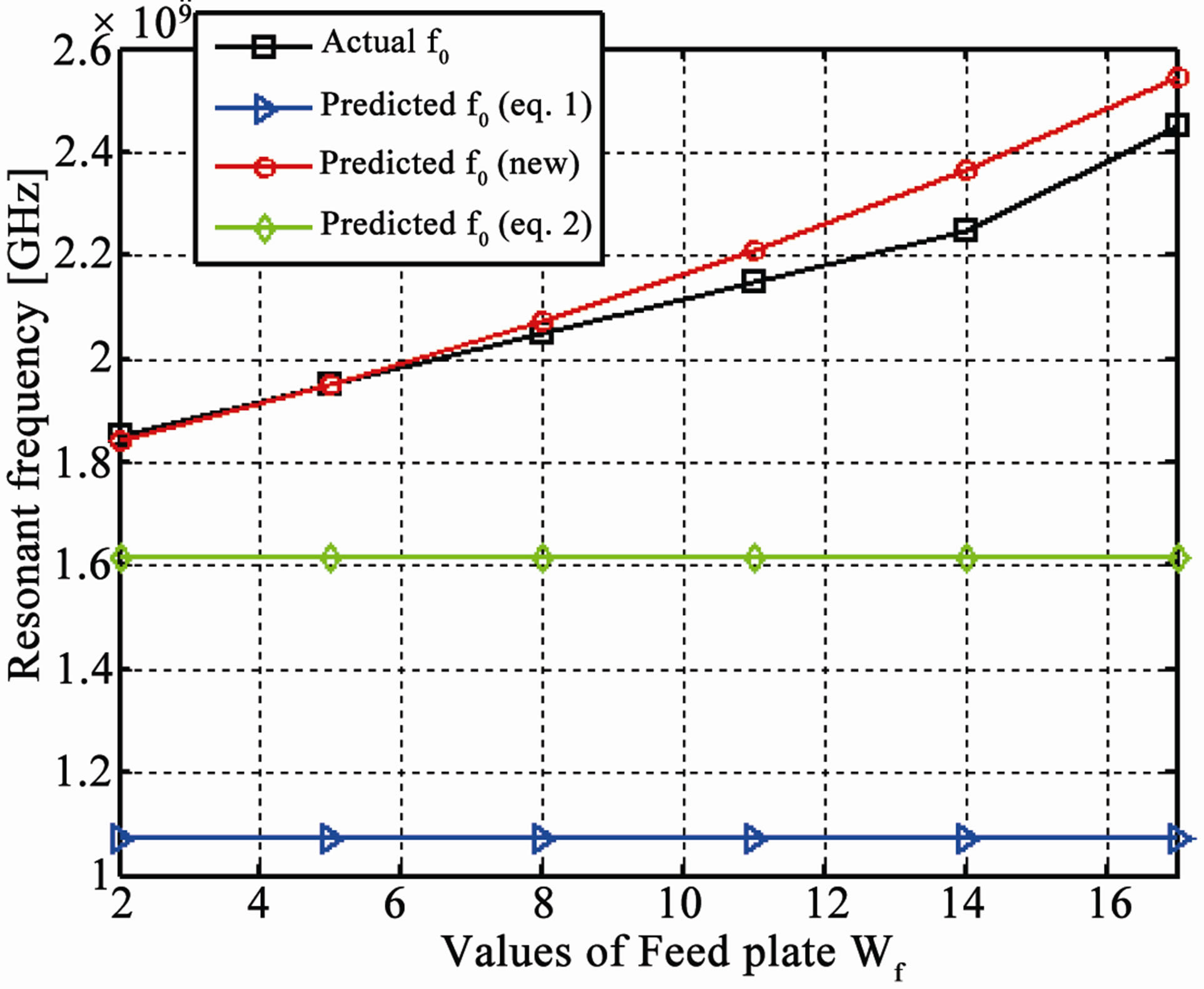
Figure 11 shows the comparisons for predicting the operational frequency of PIFA among Equation (1), Equation (2) and the new empirical equation (Equation (3)) for the changes in the values of length, width and height of the top plate of PIFA, with the feed at the top edge of top plate and the simulated resonant frequencies are taken as the actual operational frequencies. The comparisons show that the Equations (1) and (2) give poor prediction of the operational frequency of the PIFA and the predictions are the poorest when changes are made in the parameters other than the length, width of the top plate and width of the shorting plate. It is evident that the new empirical equation gives a much better prediction of the resonant frequency than the previous two equations. There is no significant effect on the resonant frequency even if we replace the thin FR4 substrate with air as shown in Figure 11. In some configurations of PIFA, the shorting plate is used at edge of the top plate and the feeding configuration is vertically downward under the top plate [15-17,26]. In this case, the horizontal distance Lb should be taken between the feed plate and one side edge of the top plate and the equation still holds. Figure 12 shows the comparisons for prediction of the operational frequency of PIFA for changes in the widths of feed [26] and shorting plates [16,17] when the feed is provided in the middle of the top plate. On average, as compared to the old empirical equation, the new proposed equation provides 35% more accuracy in predicting the operational
 (a)
(a)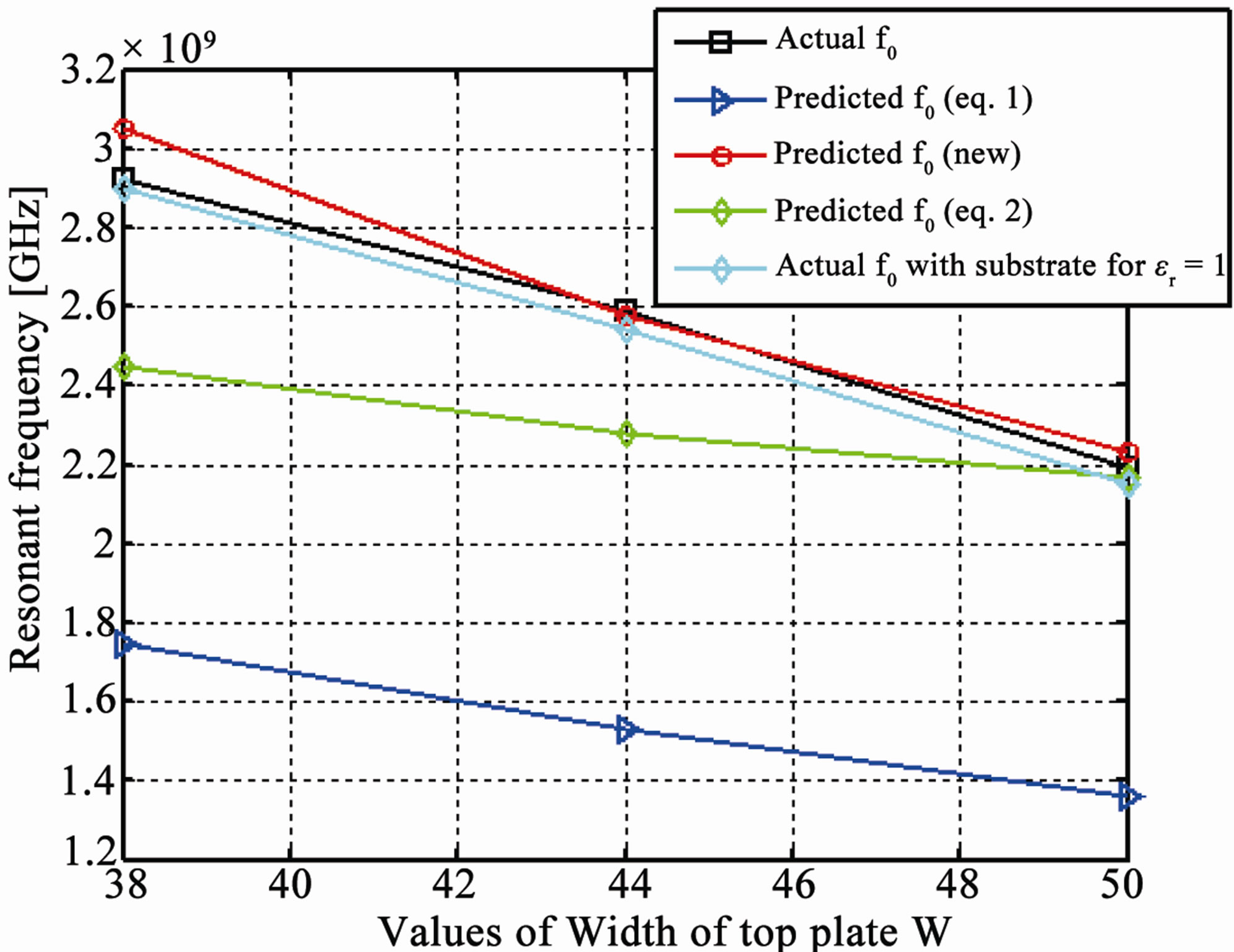 (b)
(b)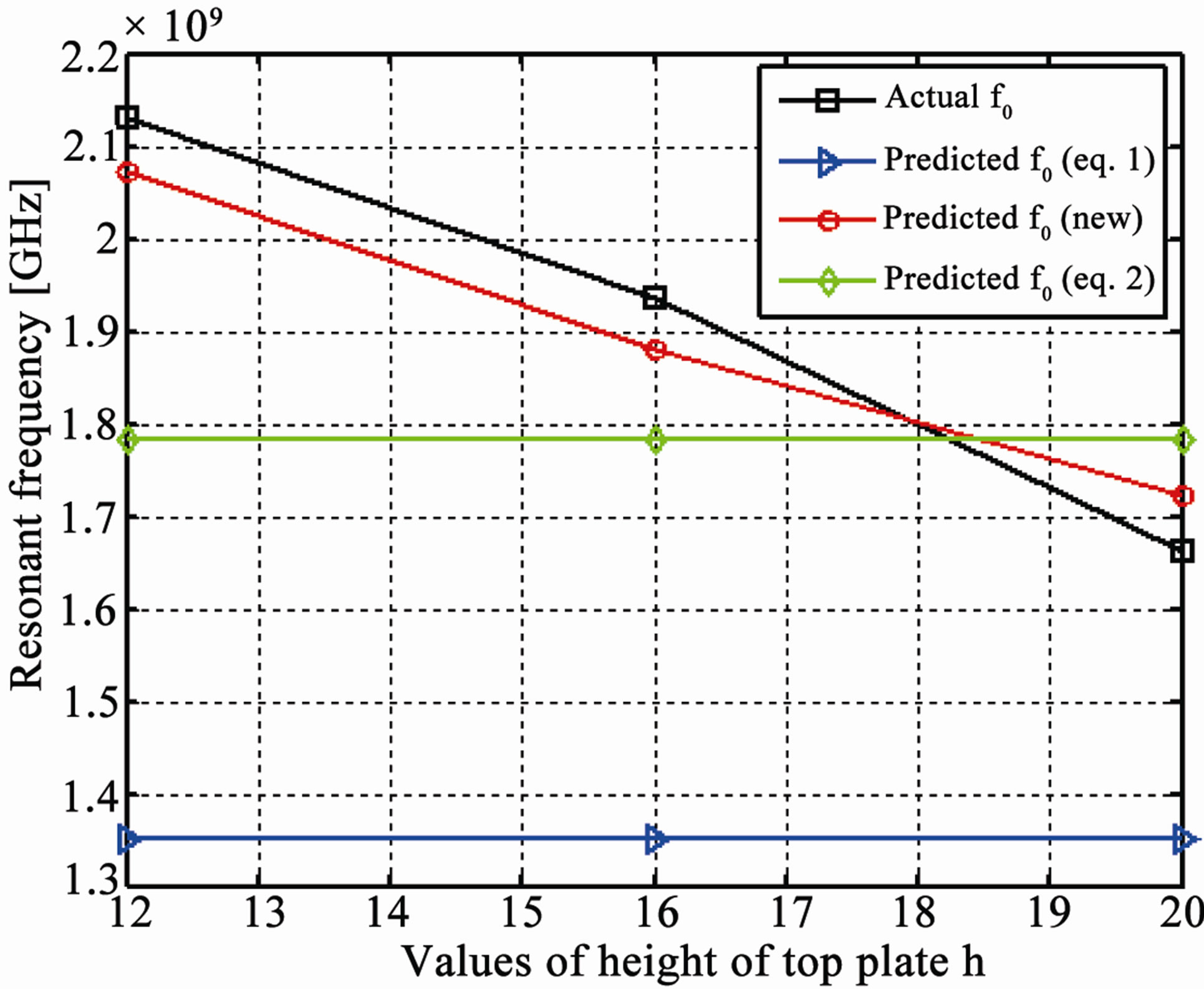 (c)
(c)
Figure 11. (a) Comparisons among Equations (1) and (2) and new equation for different values of length of top plate; (b) Comparisons among Equations (1) and (2) and new equation for different values of width of top plate; (c) Comparison among Equations (1) and (2) and new equation for different values of height of top plate.
 (a)
(a)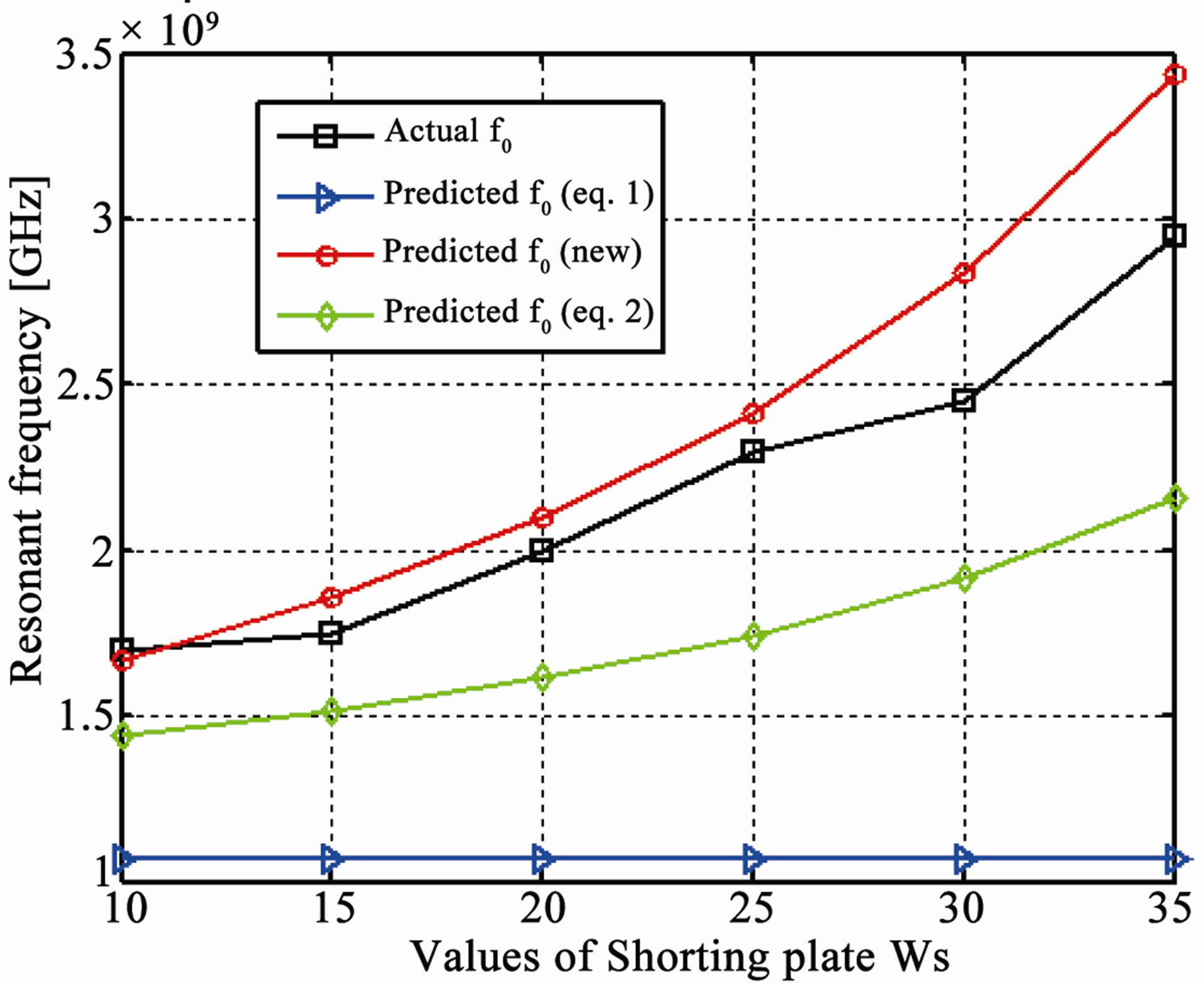 (b)
(b)
Figure 12. (a) Comparison among Equations (1) and (2) and new equation for different values of width of feed plate Wf; (b) Comparison among Equations (1) and (2) and new equation for different values of width of shorting plate Ws.
frequency of the PIFA. This new equation can provide much more accurate prediction of the resonant frequency when the whole PIFA structure is placed on the edge of ground plane and the feed is provided at the upper edge of the top plate i.e. X = Lz = Lu = 0 mm. We can have even better prediction of the resonant frequency by adding the dimensions of ground plane in above equation but these dimensions are ignored due to the fact that the resonant frequency is less affected by the variations of these dimensions and also it will make the equation complex. This new equation gives the prediction of the first resonant frequency of the antenna. It has been tested that the new equation can be applied for applications where the antenna size is smaller than one wavelength, i.e., h + W + L < λ.
5. Conclusions
We have shown that the PIFA characteristics are affected by a number of parameters. The conclusions are summarised as follows:
1) The radiation pattern of PIFA is basically dependent on the size and shape of the top plate and is affected by the dimensions of the ground plane and the position of PIFA on the ground plane.
2) By increasing the length, width or height of the top plate, the resonant frequency decreases.
3) By increasing the height of the top plate, the fractional impedance bandwidth increases but as PIFA needs to be of low profile so it limits the height to be used for increasing the impedance bandwidth.
4) The greater the size of the top plate, the more directive will be the radiation pattern which means that it will have higher gain and directivity as well. If we decrease the size (length or width) of the top plate, the directivity of antenna decreases and the intensity of radiation pattern behind the ground plane increases.
5) By increasing the widths of shorting plate or feed plate, the distance of shorting plate from the edge of the top plate and the horizontal distance of feeding position from shorting plate, the resonant frequency increases.
6) The width of feed plate is very effective parameter in broadening the bandwidth of the PIFA. The maximum fractional bandwidth achieved is up to 65%. As the increase in feed and shorting plates increases the resonant frequency, the shorting plate should be narrow and the feed plate should be larger to get the maximum impedance bandwidth.
7) The resonant frequency is also affected by the ground plane dimensions and position of PIFA on the ground plane.
8) The minimum total ground dimensions for maximum impedance bandwidth should be equal or greater than λ/2 i.e. length + width of the ground plane ≥ λ/2.
9) A new empirical equation is presented for predicting the resonant frequency of PIFA. The average percentage error found between the predicted and the actual operational frequencies is less than 3%.
REFERENCES
- K. Hirasawa and M. Haneishi, “Analysis, Design, and Measurement of Small and Low-Profile Antennas,” Artech House, Boston, 1992.
- C. A. Balanis, “Modern Antenna Handbook,” John Wiley & Sons, Hoboken, 2008.
- P. S. Hall, E. Lee and C. T. P. Song, “Planar Inverted-F Antennas, Chapter 7,” In: by R. Waterhouse, Ed., Printed Antennas for Wireless Communications, John Wiley & Sons, Hoboken, 2007.
- Y. Huang and K. Boyle, “Antennas: From Theory to Practice,” John Wiley & Sons, Hoboken, 2008.
- Z. Li, Y. Rahmat-Samii and T. Kaiponen, ”Bandwidth Study of a Dual Band PIFA on a Fixed Substrate for Wireless Communication,” IEEE Transactions on Antennas and Propagation, Vol. 1, Provo, 2003, pp. 22-27.
- P. Song, P. S. Hall, H. Ghafouri-Shiraz and D. Wake, “Triple Band Planar Inverted-F Antenna for Handheld Devices,” Electronics Letters, Vol. 36, No. 2, 2000, pp. 112-114. doi:10.1049/el:20000131
- D. Liu and B. Gaueher, “A Tri-Band Antenna for WLAN Applications,” Proceedings of the IEEE Antenna Propagation Society International Symposium and USNC/ URSI National Radio Science Meeting, Vol. 2, Columbus, June 2003, pp. 18-21.
- M. Manteghi and Y. R. Samii, “Novel compact Tri-Band Two-Element and Four-Element MIMO Antenna Designs,” IEEE Antenna Propagation Society International Symposium, Albuquerque, 9-14 July 2006, pp. 4443-4446. doi:10.1109/APS.2006.1711620
- Y. Gao, C. C. Chiau, X. Chen and C. G. Parini, “A Compact Dual-Element PIFA Array for MIMO Terminals,” Loughborough Antennas & Propagation Conference, Loughborough, 4-5 April 2005.
- H. Haruki and Kobayashi, “The Inverted-F Antenna for Portable Radio Units,” Conv. Rec. IECE Japan (in Japanese), March 1982, p. 613.
- K. L. Wang, “Planar Antennas for Wireless Communications,” Wiley-Interscience, Hoboken, 2003.
- P. S. Hall, C. T. P. Song, H. H. Lin, H. M. Chen, Y. F. Lin and P. S. Cheng, “Parametric Study on the Characteristics of Planar Inverted-F Antenna,” IEE Proceeding of Microwave Antennas and Propagation, Vol. 152, No. 6, 2005.
- Inverted-F Antenna Design. http://www.supernec.com/ifa.htm.
- K. L. Virga, and Y. R. Samii, “Low-Profile EnhancedBandwidth PIFA Antennas for Wireless Communication Packaging,” IEEE Transaction on Microwave Theory and Techniques, Vol. 45, No. 10, 1997, pp. 1879-1888. doi:10.1109/22.641786
- N. A. Saidatul, A. A. H. Azremi, P. J. Soh, R. B. Ahmad and S. R. Norra, “A Parametric Study of Broadband Planar Inverted-F Antenna for WLAN Application,” International Conference on Electronic Design, Penang, 1-3 December 2008, pp. 1-6.
- T. Y. Wu and K. L. Wong, “On the Impedance Bandwidth of a Planar Inverted-F Antenna for Mobile Handsets,” Microwave and Optical Technology Letters, Vol. 32, No. 4, 2002, pp. 249-251. doi:10.1002/mop.10145
- H. M. Chen and Y. F. Lin, “Experimental and Simulated Studies of Planar Inverted-F Antenna,” IEEE International Workshop on Antenna Technology, Singapore, 7-9 March 2005, pp. 299-302.
- M. C. Huynh and W. Stutzman, “Ground Plane Effects on Planar Inverted-F Antenna (PIFA) Performance,” IEE Proceedings Microwave Propagation, Vol. 150, No. 4, 2003, pp. 209-213.
- A. T. Arkko, “Affects of Ground Plane Size on the FreeSpace Performance of Mobile Handset PIFA Antenna,” Nokia Corporation, Nokia Mobile Phones, Espoo.
- A. T. Arkko and E. A. Lehtola, “Simulated Impedance Bandwidths, Gains, Radiation Patterns and SAR Values of a Helical and a PIFA Antenna on Top of Different Ground Planes,” 11th International Conference on Antennas and Propagation, Vol. 2, 17-20 April 2001, pp. 651-654. doi:10.1049/cp:20010370
- A. K. Bhattacharya, “Effects of Ground Plane and Dielectric Truncations on the Efficiency of a Printed Structure,” IEEE Transactions on Antenna and Propagation, Vol. 39, No. 3, 1991, pp. 269-272.
- S. Fujio, “Effects of Ground Size on Plate Inverted-F Antenna,” IEEE International Workshop on Antenna Technology, Small Antennas and Novel Materials, White Plain, 6-8 March 2006, pp. 269-272. doi:10.1109/IWAT.2006.1609027
- D. Liu and B. Gaucher, “The Inverted-F Antenna Height Effects on Bandwidth,” IEEE Antenna Propagation Society International Symposium, Washington, 3-8 July 2005, pp. 367-370.
- M. C. Fabres, E. A. Daviu, A. V. Nogueira and M. F. Bataller, “The Theory of Characteristic Modes Revisited: A Contribution to the Design of Antennas for Modern Applications,” IEEE Antennas and Propagation Magazine, Vol. 49, No. 5, 2007, pp. 52-68.
- H. T. Chattha, Y. Huang and Y. Lu, “PIFA Bandwidth Enhancement by Changing the Widths of Feed and Shorting Plates,” IEEE Antennas and Wireless Propagation Letters, Vol. 8, Salt Lake City, 2009, pp. 637-640. doi:10.1109/LAWP.2009.2023251
- R. Feick, H. Carrasco, M. Olmos and H. D. Hristov, “PIFA Input Bandwidth Enhancement by Changing Feed Plate Silhouette,” Electronics Letters, Vol. 40, No. 5, 2007, pp. 921-922.