Smart Grid and Renewable Energy
Vol.5 No.9(2014), Article ID:49590,13 pages
DOI:10.4236/sgre.2014.59020
Behavior an Induction Generator without and with a Voltage Regulator
M. L. Elhafyani1*, S. Zouggar1, M. Benkaddour2, A. Aziz1
1Laboratory of Electrical Engineering and Maintenance (LEEM), University Mohammed 1, Oujda, Morocco
2Department of Physics, Faculty of Science, University Mohammed 1, Oujda, Morocco
Email: *m_elhafyani@yahoo.fr
Copyright © 2014 by authors and Scientific Research Publishing Inc.
This work is licensed under the Creative Commons Attribution International License (CC BY).
http://creativecommons.org/licenses/by/4.0/


Received 26 June 2014; revised 1 August 2014; accepted 12 August 2014
ABSTRACT
During the isolated use of a wind system, the output voltage of the self-excited induction generator depends on the variation characteristic of its parameters: the excitation condensers, the drive speed and the load. Therefore, the regulation of the tension appears to be of great interest. We focused on the use of an analogical regulator of tension, with the aim of controlling the tension at the exit of the self-excited induction generator. So we modelled, implanted and simulated a wind system (Self-excited induction generator, converters (AC/DC, DC/DC) and load it) in the Orcad/Pspice environment. In the first time the behaviour of the asynchronous generator was analyzed when the load, the excitation capacitor and the drive speed vary in the absence of any form of regulation. This analysis was conducted with the aim of defining the limits of the machine exploitation. In the second time the functioning mode is controlled by an analogical control of tension. The results of simulation show the good performances of the system during the application of the proposed voltage regulator.
Keywords:Wind Power, Self-Excited Induction Generator, Converters (Buck-Boost), Regulation

1. Introduction
The exploitation of the renewable energy sources raises a growing interest, not only in the Third World countries, but also in the industrialized countries, particularly for the developing countries and for any isolated site generally. The use of the mechanical converters (synchronous machine, asynchronous machine), is a subject of studies and research in the range of products of the electric power [1] -[12] . As far as the production of low power electrical energy (<50 kw) is concerned, the three-phase self-excited induction generator (SEIG) with cage or wound-rotor, competes as a generator with the synchronous machine. This is due primarily to its sturdiness, robustness, its simplicity of excitation (simple connection of condensers at the stator boundaries) and its relatively modest cost.
During the isolated use of the asynchronous machine [1] [10] -[12] , a variation of the capacity, load or diver speed involves an imbalance of the stator output voltage. This problem can be solved by operating, the condensers, the load or the drive speed by the intermediary of a regulator.
In this paper, we present the capacity variation effect, speed of drive and load as function of the wind system without and with analogical regulator.
2. Behavior of the Machine without the Voltage Regulator
2.1. Modelling of the Wind System
2.1.1. Equivalent Circuit of the Wind System
The Figure 1 represents the synoptic diagram of an asynchronous machine (1.5 KW) related to on the energy converter (AC-DC) and feeds a resistive load (RS):
The Induction Asynchronous Generator does not excite without external power given to its stator, the rotor windings are shorted. Rotor winding will have current only when there is connection of voltage from Grid/battery operated AC source.
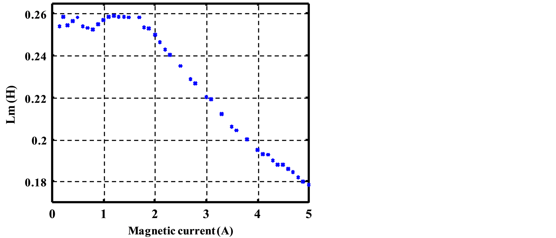
The initiation of the generator is possible only from a speed-dependent threshold value of the capacitances and the magnetic state of the machine (linear portion of the magnetization curve) (Figure 2).
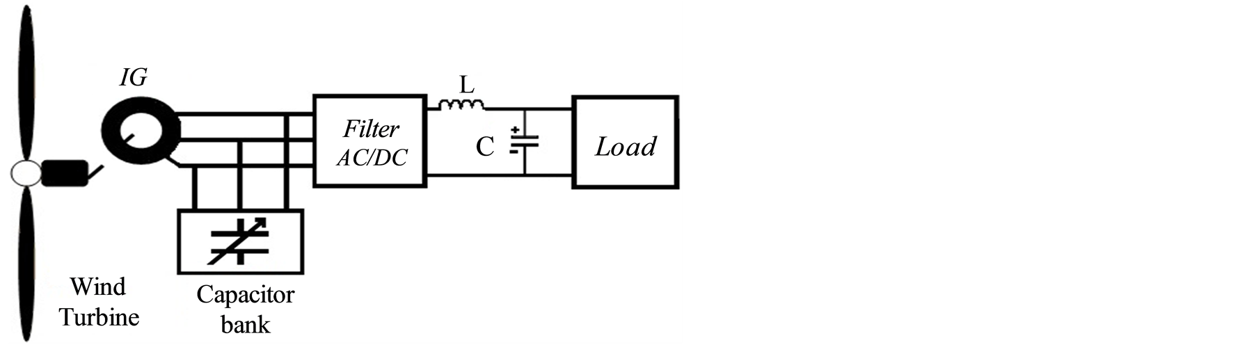
Figure 1. Synoptic diagram of a SEIG with a rectifier dependent has a resistive load.
2.1.2. Modelling of the Wind-Turbine
By applying the theory of momentum and Bernoulli’s theorem, we can determine the incident power (theoretical power) due to wind:
 (1)
(1)
The wind turbine acts like a primary strength to train the induction generator [7] . The power produced by the wind turbine part is given by the following formula
 (2)
(2)
where:
ρ: the air density (ρ = 1.225 kg/m3 at atmospheric pressure);
A: the swept area (m2);
Cp: the coefficient of wind turbine;
Vw: the wind velocity (m/sec);
Cp(λ) is called the power coefficient, which expresses the aerodynamic efficiency of the turbine. It depends on the ratio λ, which represents the ratio between the speed at the end of the blades and the wind speed. The ratio λ can be expressed by the following relation:
 (3)
(3)
2.1.3. Symbolization of the Mechanical Equation (See Figure 3)
The implementation and the simulation of the self-excited asynchronous machine were achieved by using the Orcad-Pspice tool whose libraries are rich in electrical and analogical components, and by elaborating symbolization procedures [13] -[15] .
In electrical technology, there is no software for simulating mechanical parameters directly. We did this simulation on the Orcad/Pspice software-using the following analogies:
The mechanical equation of the induction machine is given by the following formula:
 (4)
(4)
 (5)
(5)
The electromagnetic torque Te is given by:
 (6)
(6)
With:
J: Moment of inertia;
Te: Couple électromagnétique en N×m;
Tr: Load torque (N·m);
Bm: The constant friction (kg·m2/s);
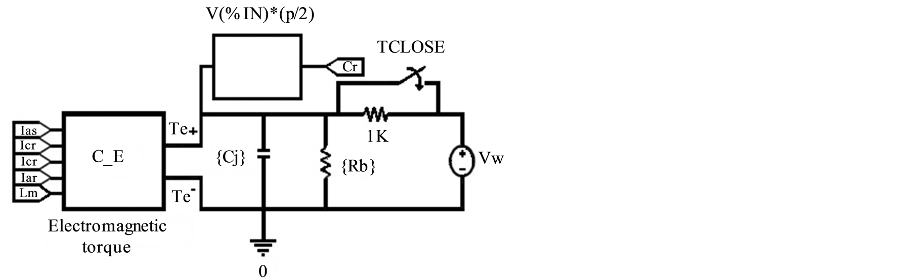
Figure 3. Electrical diagram of the mechanical equation.
ωr et ωmr: Electrical and mechanical speed (rad/s).
Applying the analogy between mechanical and electrical variables, we have:
 (7)
(7)
2.2. Simulation Results without the Voltage Regulator
2.2.1. Speed Variations Effect
Figure 4 represents the stator voltage variation
at the output of the rectifier according to the drive speed of the machine for a
capacity of C = 80 μF and a load RS = 70 Ω. We note that the
voltage increases with the speed (the nominal voltage
 corresponds to a speed of the wr = 298 rad/s).
2.2.2. Load Variations Effect
Figure 5 illustrates the evolution of the stator
tension on the outlet side of the rectifier according to the load at different values
of the drive speed, and at the excitation capacitor C = 80 mF. One fixes shows that
a variation speed or load involves a variation of the tension (the nominal voltage
 corresponds to a load RS = 70 Ω, a C = 80 mF capacity and a speed
wr = 298 rad/s).
corresponds to a load RS = 70 Ω, a C = 80 mF capacity and a speed
wr = 298 rad/s).
2.2.3. Capacity Variations Effect
Figure 6 represents the voltage waveform evolution of a stator phase (Figure 1) according it’s of the self excitation capacitor C. At several values of the speed, one observes that the voltage waveform increases with the capacity value knowing well that the induction generator cannot start unless the excitation capacitor has reached a certain threshold.
The objective of these tests is to study the behavior of the asynchronous machine (SEIG) during variation of the speed, capacity and load, and to determine the exploitation limits the generator without resorting to any form of regulation.
3. Modeling and Simulation the Wind System in the Orcad-Pspice Environment
3.1. Behaviour of the Machine with the Voltage Regulator
The synoptic diagram equivalent of the system (asynchronous machine, energy converters (AC-DC, DC-DC, regulator, and load) is given in Figure 7. The voltage regulator is intended to control the output voltage of the reversible inverter Buck-Boost in spite of the variations of speed, load and capacity.
This diagram is implemented and simulated in the Orcad-Pspice environment.
Generally the conception and the modeling of a wind system (self-excited induction machine, static converters (AC/DC and DC/DC)) require the use of performing simulators on electronics and electrical engineering to implement each block of the wind system and in particular the model of the self-excited induction generator in
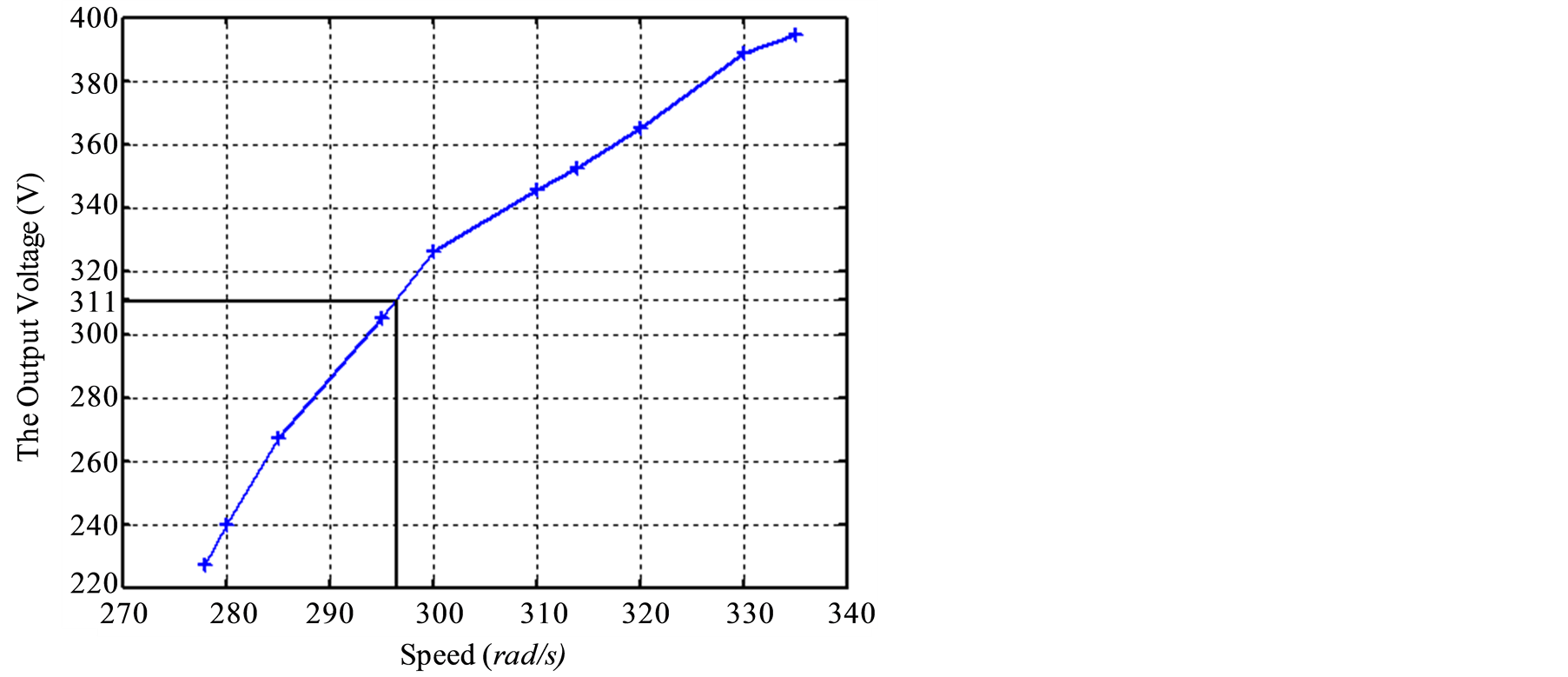
Figure 4. The output voltage evolution of the system (Figure 1) as a function of the drive speed at (C = 80 mF and RS = 70 Ω).
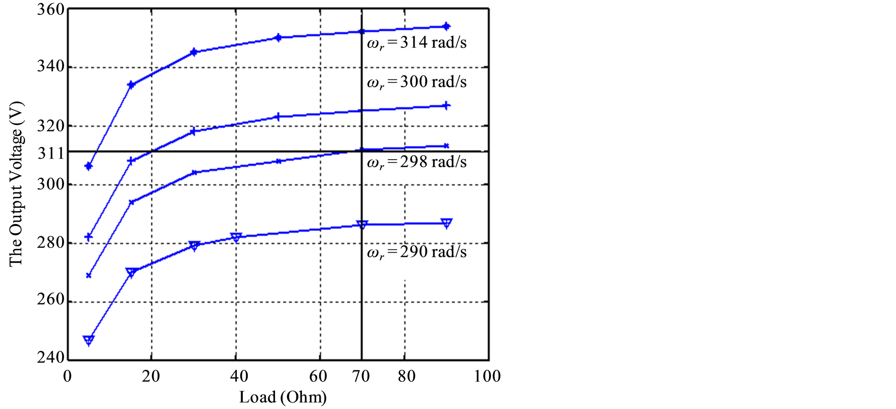
Figure 5. Variation of the output tension of the rectifier as a function of the load for different speeds (C = 80 mF).
transient state. In our research framework, the Orcad/Pspice software can largely meet our need in electric simulations.
The main advantages of this software are:
• Orcad/Pspice simulation software is the most widely used in the industry.
• It is based on the industry standard SPICE and therefore gives access to libraries of models developed by industrial manufacturers, and the availability of a large number of libraries on the market.
• It allows the combination of digital and analog components without any problems.
• It allows the ability to integrate Orcad electrical schematics in Matlab/Simulink tool especially with the version 16 of Orcad/Pspice.
• It is a very complete software because it allows to simulate all aspects of systems that we find in electrical engineering: power electronics, analog and digital electronic control, slaving, and mechanics.
3.2. Modelling of the Voltage Regulator
The model of the voltage regulator is given in Figure 8.
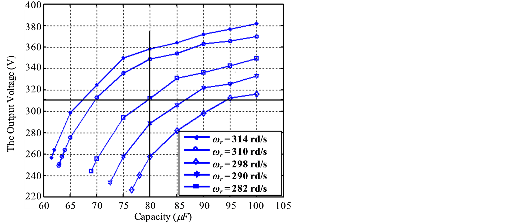
Figure 6. Evolution of the output tension of the system (Figure 1) according to the capacity for different speeds at (RS = 70 Ω).
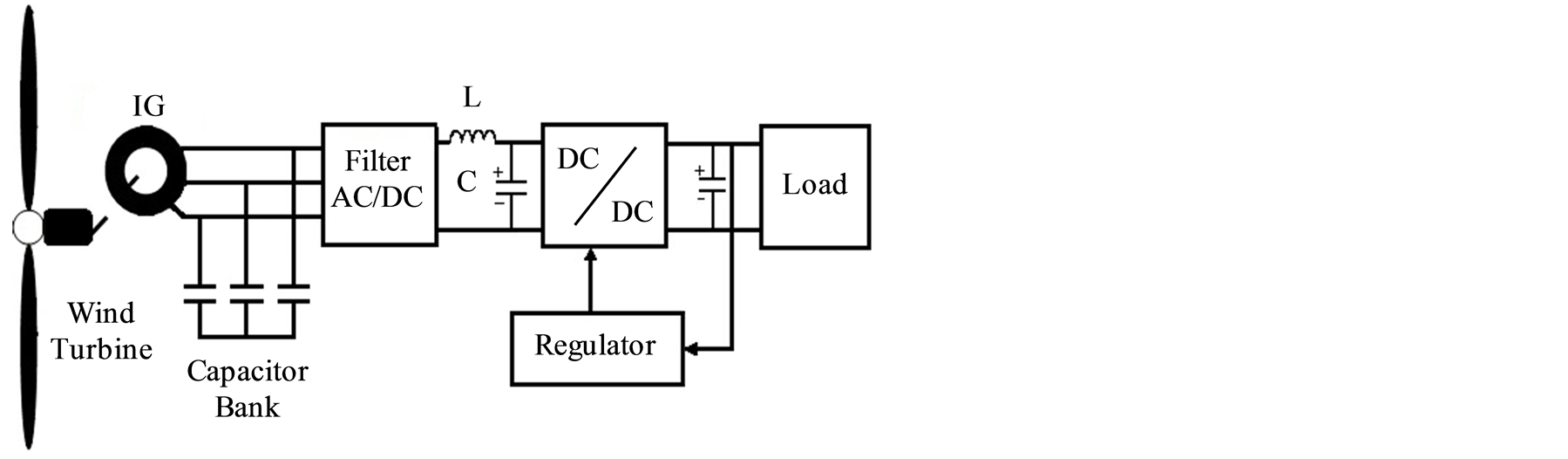
Figure 7. Descriptive diagram of the system.
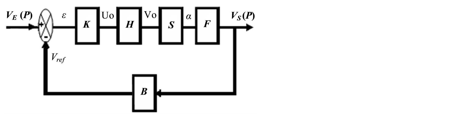
Figure 8. Equivalent circuit of the voltage regulator.
The different transfer functions of the various elements of Figure 8 are as follows:
B: divider of return:
 (8)
(8)
K: Corrector Proportional-Integrator PI
 (9)
(9)
H: Corrector Integrator
 (10)
(10)
S: Comparator circuit Puls Wave Modulation (PWM):
 (11)
(11)
The transfer functions of the inverter:
 (12)
(12)
with: α = Cyclic ratio P: Laplacian operator The total function of transfer of the system is as follows:
 (13)
(13)
with:

3.3. The Analog Voltage Control Algorithm
When you submit your final version, after your paper has been accepted, prepare it in two-column format, including figures and table We have implemented in the environment Orcad/Pspice the wind system of Figure 7 without the Analog Voltage Control (AVC) with taking into account the parameters of the converter given in the previous paragraph. Then we have analyzed the adaptation of the generator SEIG (LEROY SOMER: LA3 loop asynchronous machine 1.5 KW) and studied the effect of the variation of the resistive load (RS), the excitation capacity, the drive speed and the duty cycle to the output system.
The IRF450 switch of the converter is controlled by a pulse generator outputting a square wave of high frequency 100 kHz and a variable duty ratio.
3.3.1. Influence of the Load and Duty Cycle of the Voltage
In Figure 9, we have shown the output voltage of the converter according to the RS load and the duty cycle a for an excitation capacity C = 70 μF and a driving speed wr = 298 rad/s. From these curves of the figure below we deduced that the output voltage of the converter increases with increasing the RS load and the duty cycle.
3.3.2. Influence of the Capacity and the Duty Cycle on the Output Voltage
Figure 10 illustrates the voltage at the output
of the Buck/ Boost converter as a function of the capacity and the duty ratio a
for a resistive load
 and a driving speed wr around 314 rad/s. From these curves we have observed that
the output voltage of the converter depends on the self-excitation capacity and
the duty cycle.
and a driving speed wr around 314 rad/s. From these curves we have observed that
the output voltage of the converter depends on the self-excitation capacity and
the duty cycle.
The voltage required by our specifications
 is given by a capacitor
 and a ratio a of 0.25.
3.3.3. Influence of the Speed and the Duty Cycle on the Output Voltage
Figure 11 shows the output voltage of the converter as a function of the load and the duty cycle a for an excitation capacity of 75 μF and a resistive load of 70 W.
From these curves we found that the output voltage of the converter also varies with the duty cycle when the speed varies.
As to the Buck/boost converter, the variations in the output voltage according to the duty ratio, obtained in the simulation Orcad/Pspice, are consistent with the relation (14) and the proportionality of the duty ratio with the voltage at the variation in the mechanical and electrical quantities of the machine.
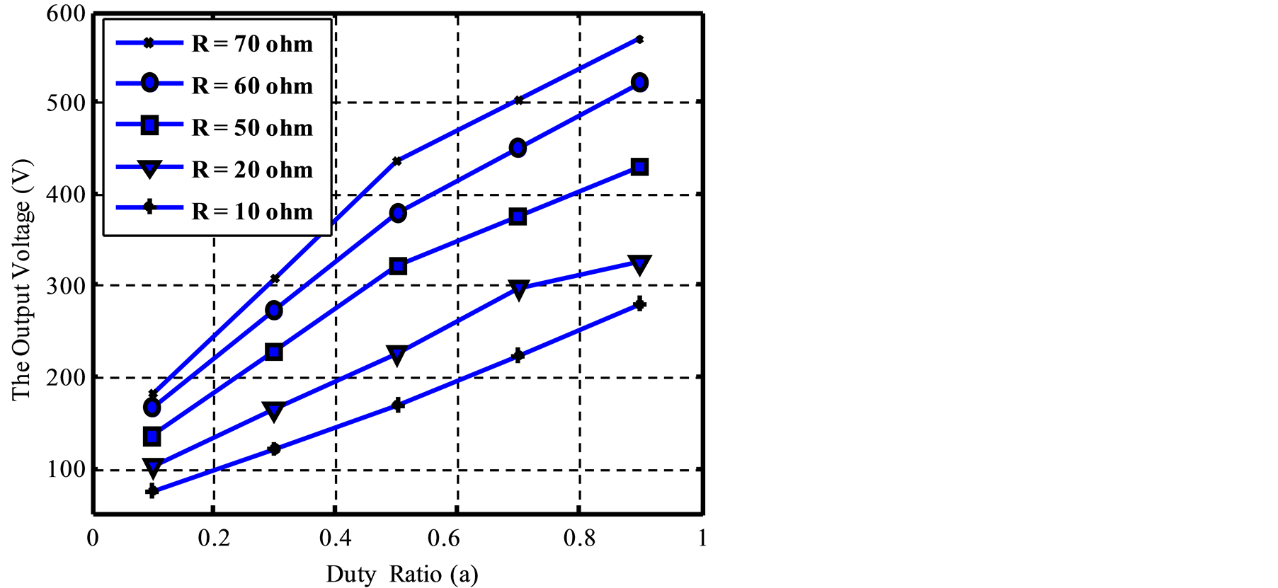
Figure 9. Typical simulation of the voltage VS at the output of the buck/boost converter in function of the load and the duty ratio: C = 70 μF and wr = 298 rad/s.
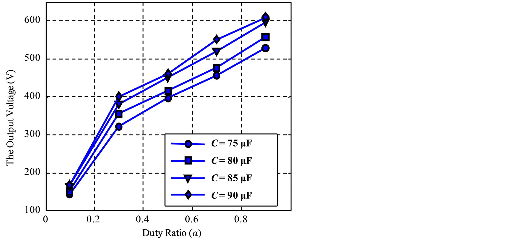
Figure 10. Typical simulation
of the voltage VS at the output of the buck/boost converter according
to the capacity and the duty ratio for:
 and
and .
.
 (14)
(14)
3.3.4. Summary of Variations in the Parameters Load, Speed and Capacity
We saw in the previous section when the excitation capacity, the load and the driving speed varies, an adaptation of the system must be achieved by including between the generator (asynchronous machines SEIG + Rectifier) and the RS load an adapter (Figure 1). This adapter must also include the DC-DC power converter, an AVC command to regulate the voltage in the operating conditions considered. The AVC command must meet our specifications so as to maintain a constant voltage on the terminals of the wind system studied.
So, for a given a wind system operating. The design of a command to adjust the duty cycle a, depending on weather changes (wind speed), changes of the capacity and of the load is needed in order to operate the wind system in optimal conditions.
Figure 12 shows the search algorithm of the duty cycle as a function of the output voltage whatever the variation of the SEIG characteristic.
In the following paragraph, we study the design and the operation in the Orcad/Pspice environment, of the Analog Voltage Control (AVC) linked to a converter (buck/boost) operating at high frequency (100 KHz).
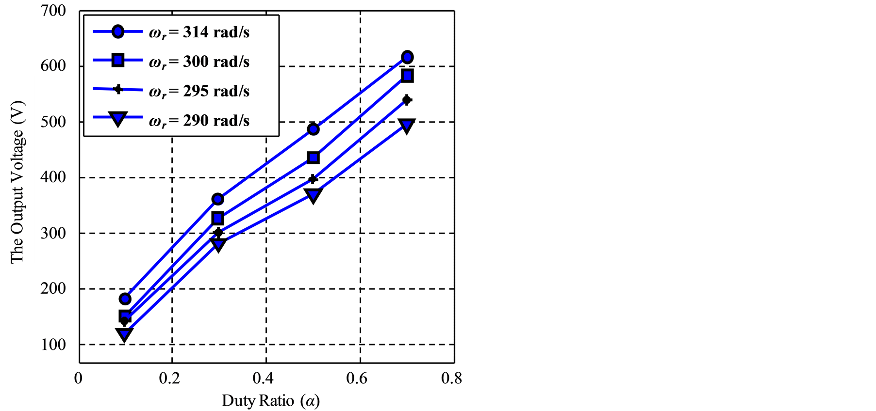
Figure 11. Typical simulation of the voltage VS at the output of buck/boost converter according to the driving speed and the duty cycle for: C = 75 µF and RS = 70 W.
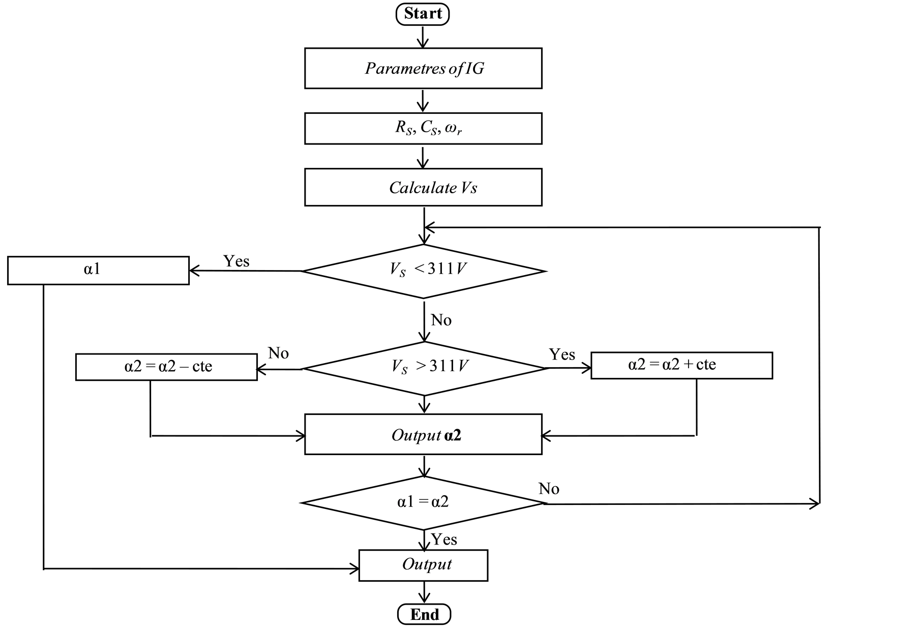
Figure 12. Algorithm for calculating the duty ratio.
4. Results of Simulation Analog Voltage Control Algorithm
Figure 13 represents the nominal output voltage of the inverter at fixed values of the capacity of self excitation, load and wind speed.
Figure 14 illustrates the output voltage evolution of the inverter when the driver speed decreases by 8%. We note as light variation of the voltage at the time of the speed variation and then it is stabilized at its initial value (The wished value).
The voltage output variation of the inverter, when the self-excitation capacitor increases by 12%, is showed in Figure 15. We observe that the output voltage reaches the nominal value of stabilization after as light increase at the time of the capacity variation.
Figure 16 represents the output voltage evolution of the system (Figure 7) when the load increases by 22%. We note a slight variation of the voltage at the time of the load variation; then is stabilized at the nominal value fixed by our schedule of conditions.
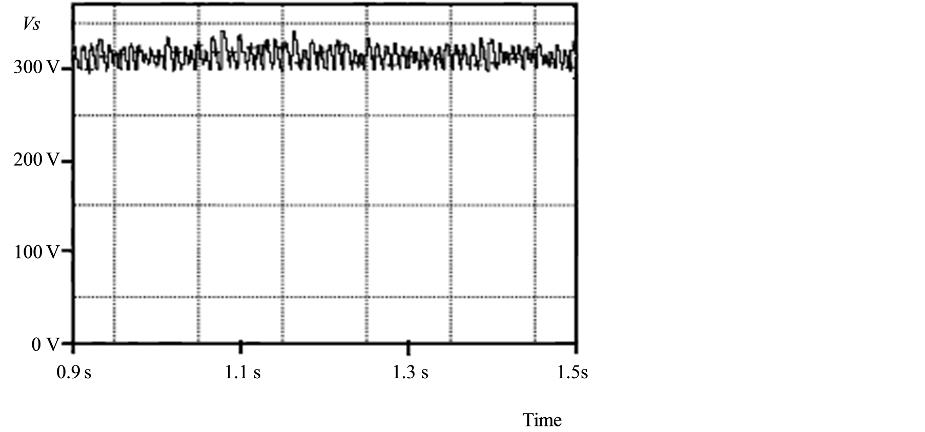
Figure 13. Variation of the output voltage of the chopper (Figure 5) at wr = 298 rad/s, C = 80 mF and RS = 70 W.
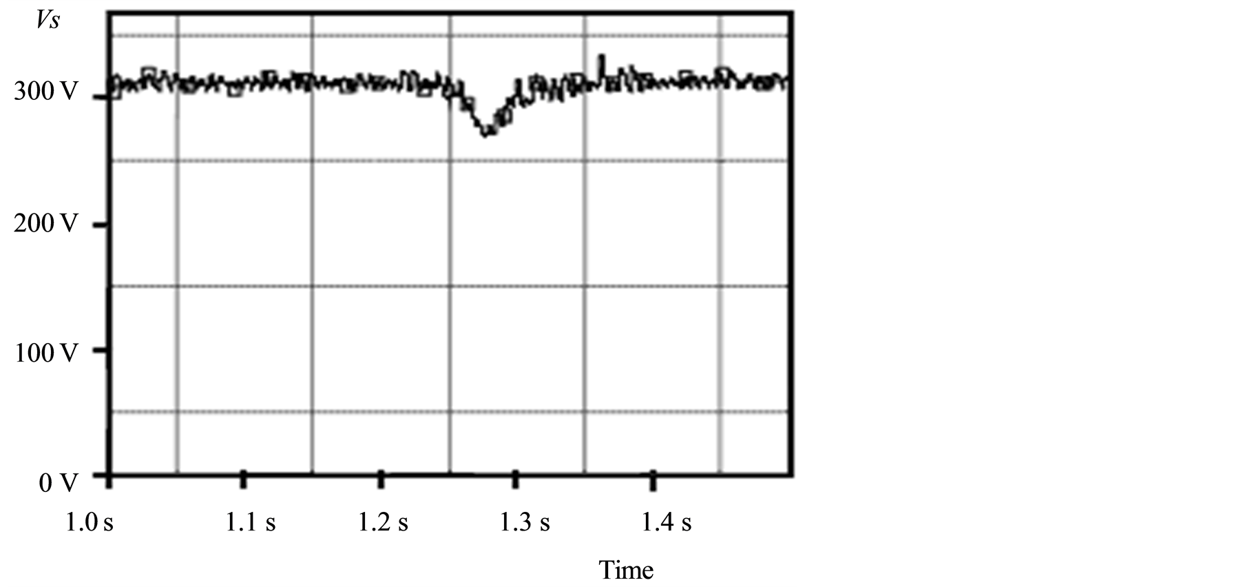
Figure 14. Variation of the output voltage of the chopper when the speed decreases by 8% at C = 80 mF and RS = 70 W.
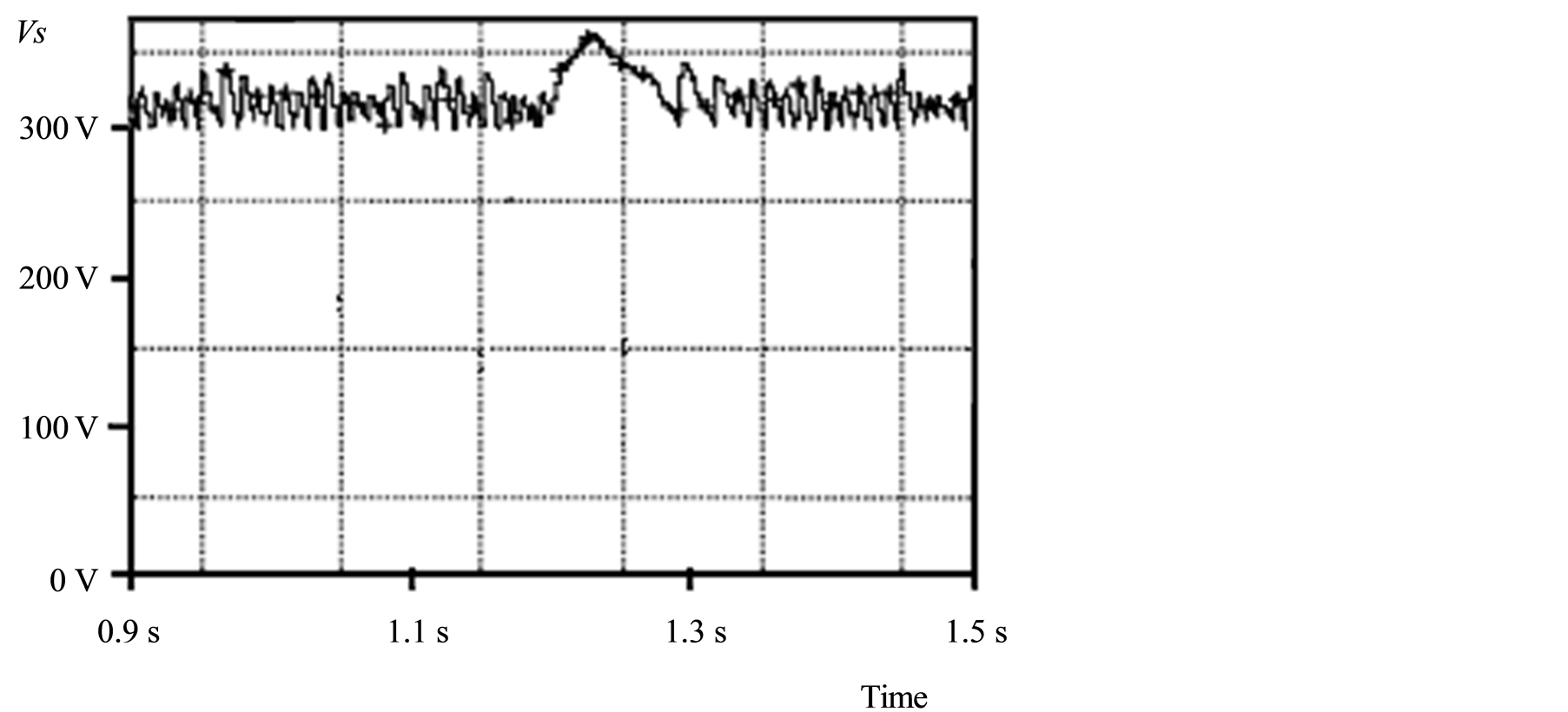
Figure 15. Variation of the output voltage of the chopper when the excitation capacitor increases by 12% at ωr = 298 rad/s and RS = 70 W.
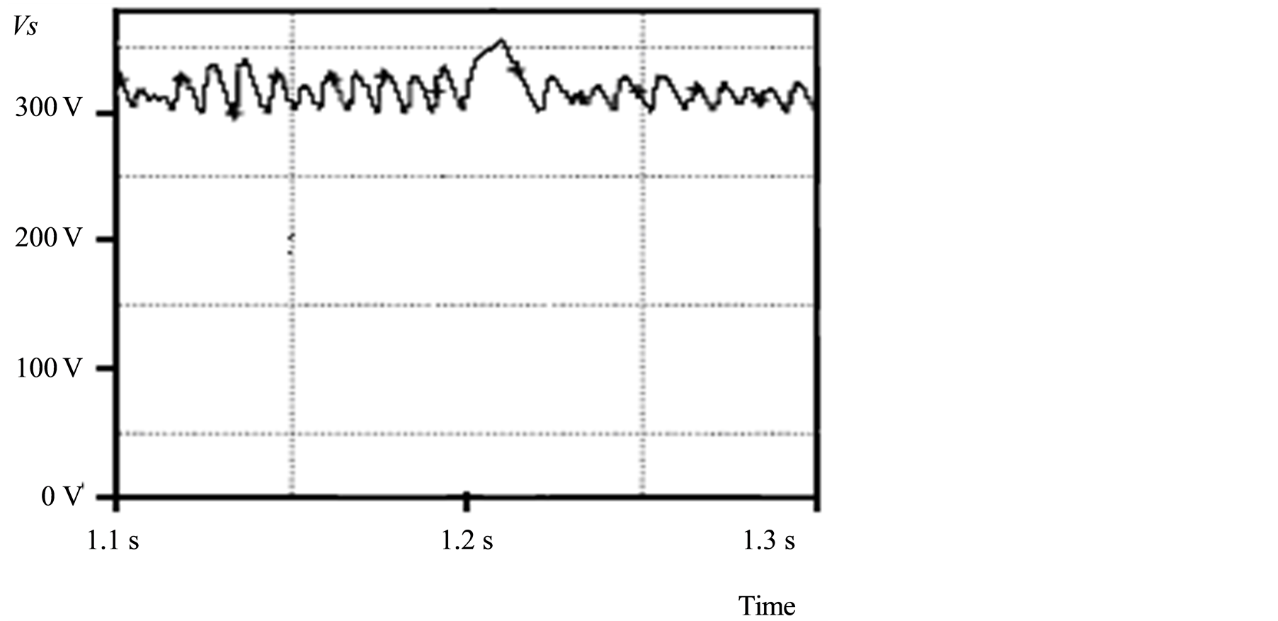
Figure 16. The output voltage evolution of the chopper when the load increases by 22% at ωr = 298 rad/s and RS = 70 W.
5. Conclusions
In this paper we proposed a robust law of the control circuit applied to a wind
system with the aim of finding a constant value of tension
 at the exit of the system provided that the drive speed does not exceed a maximum
value wr = 330 rad/s.
at the exit of the system provided that the drive speed does not exceed a maximum
value wr = 330 rad/s.
From the results of simulation of the studied system (asynchronous machine, converters (AC-DC and DC-DC) and load), it appears that:
• The voltage at the exit of the inverter is almost invariant for all the curves, even if one varies the characteristic parameters of the system (speed, capacity or load).
• The control designed makes the system oscillate around the desired tension.
• The disturbances which exist during the oscillations around the value
 are due to the transient state of the asynchronous machine and the losses in the
components of the system (Mosfet, diode and component of the regulator).
are due to the transient state of the asynchronous machine and the losses in the
components of the system (Mosfet, diode and component of the regulator).
The SEIG has the following characteristics:

References
- Elhafyani, M.L., Zouggar, S., Zidani, Y. and Benkaddour, M. (2006) Permanent and Dynamic Behaviours of Self-Excited Induction Generator in Balanced Mode. Journal of Physics: Condensed Matter, 7, 49-53.
- Premalatha, K. and Sudha, S. (2012) Self-Excitation and Voltage Control of an Induction Generator in an Independent Wind Energy Conversion System. International Journal of Modern Engineering Research (IJMER), 2, 454-461.
- Marra, E.G. and Pomilio, J.A. (2000) Spice-Assisted Simulation of the αβγ Model of Cage-Rotor Induction Machines Including Saturation. IND2000_FDI05, 497-502.
- Elhafyani, M.L., Zouggar, S. and Benkaddour, M. (2005) Comportement permanent et Transitoire d’une Génératrice asynchrone auto-excitée en régime équilibré. PREMME_05, Université My Ismail, FST-Errachidia, Maroc.
- Zidani, Y. and Naciri, M. (2001) A Numerical Analytical Approach for the optimal Capacitor used for the Self Excited Induction Generator. Proceedings of the 32nd IEEE PESC Power Electronics Specialists Conference, Vancouver, June 2001, 216-220.
- Zidani, Y. and Naciri, M. (2001) A Steady State Analysis of the Self Excited Induction Generator Controlled by an Electronic Load Governor. Proceedings of the 4th IEEE PEDS Power Electronics and Drive Systems, Bali, October 2001, 903-907.
- Mujadi, E., Sallan, J., Sanz, M. and Butterfield, P. (1999) Investigation of Self Excited Induction Generators for Wind Turbine Application. IEEE Industry Application Conference 34 IAS Annual Meeting, Arizona, October 1999, 3-7.
- Seyoum, D., Grantham, C. and Rahman, F. (2001) Analysis of an Isolated Self-Excited Induction Generator Driven by a Variabe Speed Prime Mover. AUPEC 2001, Curtin University of Technology, Perth, September 2001, 23-26.
- Mujadi, E., Gregory, B. and Bord, D. (1999) Self Excited Induction Generators for Variable-Speed Wind Turbine Generation. IEEE Industry Application Conference 34 IAS Annual Meeting, Arizona, October 1999, 343-352.
- Barara, M., Akherraz, M., Abbou, A., Elhafyani, M.L. and Moutchou, M. (2013) Fuzzy Modeling Magnetizing Curve of a Self Excited Induction Generator and Effect of Mutual Inductance. 2013 International Renewable and Sustainable Energy Conference (IRSEC), Ouarzazate, 7-9 March 2013, 287-291.
- Ouchbel, T., Zouggar, S., Elhafyani, M.L., Oukili, M., Sedik, M. and Rabhi, A. (2013) Regulation of the Excitation Reactive Power of the Asynchronous Wind Turbine at Variable Speed. Smart Grid and Renewable Energy, 4, 272-280. http://dx.doi.org/10.4236/sgre.2013.43033
- Ouchbel, T., Zouggar, S., Elhafyani, M.L., Oukili, M., Sedik, M. and Aziz, A. (2014) Power Maximization of an Asynchronous Wind Turbine with a Variable Speed Feeding a Centrifugal Pump. Journal Energy Conversion and Management (EC & M), 78, 976-984.
- Elhafyani, M.L., Zouggar, S. and Benkaddour, M. (2006) Symbolization of the Asynchronous Machine in the Orcad/ Pspice environment. JER06, EST-Oujda, Morocco.
- Aziz, A., Kassmi, K., Olivié, F. and Sarrabayrouse, G. (2005) Symbolization of the Electric Diagram of the Marketing Solar Panels in the Orcad-Pspice Environment. Rapport LAAS (05270), Toulouse, 17.
- Aziz, A., Kassmi, K., Maimouni, R., Olivié, F., Sarrabayrouse, G. and. Martinez, A. (2005) Integration of the New Components in the Library of the Orcad-Pspice Simulator. 2 Symbolization of the Electric Diagrams: Application to the Photovoltaic Systems. Rapport LAAS/CNRS (05271), Toulouse, 15.
Nomenclature
SEIG : Self-Excited Induction Generator IG : Induction Generator
 : Mechanical Rotor Speed rs,
rr : Stator and Rotor Resistances Xs, Xr : Stator and
Rotor Leakage Impedance Xm : stator Mutual Impedance C : Excitation
Capacitor
: Mechanical Rotor Speed rs,
rr : Stator and Rotor Resistances Xs, Xr : Stator and
Rotor Leakage Impedance Xm : stator Mutual Impedance C : Excitation
Capacitor
α : Cyclic Ratio AVC : Analog Voltage Control AC-DC : The energy Converter (Rectifier)
DC-DC : The energy Converter (Buck-Boost)
PWM : Pulse-Width Modulation RS : The Resistive Load Vs : The Output Voltage E : The Input Voltage Indices s and r stand for stator and rotor respectively.
NOTES

*Corresponding author.