Smart Grid and Renewable Energy
Vol.4 No.7A(2013), Article ID:37476,9 pages DOI:10.4236/sgre.2013.47A001
Vulcan/Pt/Ce Catalysts Prepared by Impregnation Using EDTA for Direct Methanol Fuel Cell, Direct Ethanol Fuel Cell, and Polymer Electrolyte Membrane Fuel Cell
![]()
1NASA-University Research Centers for Advanced Nanoscale Materials, Department of Chemistry and Physics, University of Puerto Rico, Río Piedras Campus, San Juan, USA; 2Chemistry Graduate Program, University of Puerto Rico, Río Piedras Campus, San Juan, USA; 3General Studies College, Physical Sciences Department, University of Puerto Rico, Río Piedras Campus, San Juan, USA; 4Center for Functional Nanomaterials, Brookhaven National Laboratory, Upton, USA; 5Chemistry Department, Brookhaven National Laboratory, Upton, USA.
Email: *carlos.cabrera2@upr.edu
Copyright © 2013 Rolando Guzmán-Blas et al. This is an open access article distributed under the Creative Commons Attribution License, which permits unrestricted use, distribution, and reproduction in any medium, provided the original work is properly cited.
Received March 21st, 2013; revised April 21st, 2013; accepted April 28th, 2013
Keywords: Cerium; Fuel Cell; Pt; Methanol; Ethanol; Hydrogen
ABSTRACT
A wet chemistry synthesis of Pt-Ce doped catalysts on carbon Vulcan support using an impregnation method with EDTA is presented. The composite catalyst was characterized by XRD, XPS and TEM. The catalytic activity of the prepared material was tested in a direct fuel cell using methanol, ethanol and hydrogen as fuels. The polarization and power curves showed that the Vulcan/Pt/Ce(III) doped catalysts improved the performance of the fuel cells when compared with Vulcan-Pt anode materials.
1. Introduction
Fuel cell technology is one of the most promising alternatives to obtain electric energy in an efficient way with a low environmental impact and flexible applications [1]. A fuel cell is an electrochemical device that takes oxygen from the air and a fuel to generate water and electrical power [2]. There are different types of fuel cells. In the case of polymeric fuel cells, they have gained important attention as a consequence of their applicability in transportation. This causes world global investment in PEMFCs to be growing day by day. In the case of fuel cells with a proton conducting electrolyte (PEMFC, Proton Exchange Membrane Fuel Cell), the fuel is hydrogen. Hydrogen is oxidized at the anode and the generated protons go through the membrane toward the cathode [3]:
In the cathode of the electrochemical cell, the oxygen reacts with the protons and it is reduced according to:
The global reaction in the fuel cell is:
The electrons formed at the anode of the cell flow in the external circuit during these reactions providing the electrical energy used for different applications [4].
Hydrogen fuel cells are important because they reduce global carbon dioxide (CO2) emissions and improve local air quality. They create a new industrial and technological energy base which is considered crucial for our economic needs [5].
Direct alcohol fuel cells (DAFC) have several applications in transportation and portable electronic devices. DAFC cells use an alcohol of small chain as (methanol or ethanol) as a fuel without the need of a fuel reforming process. This fact makes the DMFC simple and compact. In the case of the direct methanol fuel cells (DMFC), they present two basic disadvantages: 1) the low kinetic of the methanol electrooxidation and 2) the high crossover of methanol trough and the polymeric Nafion® membrane which causes mixed currents and a decrease in cathode efficiency. Similar disadvantages exist in the case of Direct Ethanol Fuel Cells (DEFC). However, recently, they have received special attention because ethanol has a higher energy density than methanol (8.01 kWh/kg vs. 6.09 kWh/kg). Ethanol can be produced in large amounts from biomass; it is safer than methanol and considered as a green fuel [6-9].
Direct methanol fuel cells (DMFC’s) use a proton conducting electrolyte membrane (PEM) in an acidic medium. The major improvement that has been made to acidic fuel cells, especially regarding the perfluorosulfonic-acid membrane stability and the great reduction of catalyst loadings, makes this type of fuel cell a very common and attractive one [10]. Another type of fuel cells is the alkaline fuel cell (AFC) but they present a serious problem due to the carbonation of the alkaline electrolyte from the CO2 from air or the oxidation product of the fuel [11]. Another substantial problem of alkaline fuel cells is the challenge in developing anion-exchange membranes with a good ionic conductivity and stability under the operating conditions [12].
Different fuels can be used in fuel cells. Liquid alcohols like methanol or ethanol are more easily stored and transported than hydrogen gas and also present higher energy densities and energy efficiencies than the gaseous fuels [13]. Alcohols with larger chains than ethanol, like n-butanol, are being considered as fuels nowadays. They are produced from biomass, attractive properties being high energy content, weak corrosivity and facile transportation [14].
Fuel cells have three basic components (anode, cathode and separator or membrane). Design needs to be optimized. The most important challenge is to find the ideal catalyst that promotes the oxidation of the fuel. By far, platinum-based catalysts are considered the best choice. Since platinum is a valuable material, an obvious approach is to find a catalyst that incorporates the smallest amount of platinum while giving the best performance or output voltage possible. Different researchers have found that electrodes with Pt as the principal component with other metals, oxides and non-metals enhanced the catalytic activity for methanol electrooxidation [15].
The use of cerium, specifically cerium oxide (ceria), in fuel cell catalysts was presented in the middle 2010’s [16-18]. The use of ceria has attained vital importance for its capacity to act as an oxygen buffer. In other words, ceria can release and accept oxygen. Oxidation of CO in acidic mediums is particularly important [19], since CO poisoning of pure platinum catalysts is a serious problem associated with fuel cell operation. Pt-Ceria catalysts have been prepared by supercritical carbon dioxide fluid deposition and applied in a direct methanol fuel cell and showed greater methanol oxidation activity than pure platinum [20].
Some researchers have prepared a Pt-Ce catalyst not used for fuel cell applications by arc melting technique on a water-cooled copper hearth under an argon atmosphere, which is a long procedure [21,22]. A better mixture of platinum and cerium in the final catalyst could be achieved by using a chelating agent for the cerium source. EDTA is one of the most used chelating compounds for metals that present multiple oxidation states, such as cerium. In this research we propose to use a Vulcan/Pt/Ce material prepared by the impregnation method using EDTA as a chelating agent to form a complex with cerium(III). The prepared catalysts were tested in fuel cells using hydrogen, methanol and ethanol as fuels.
2. Catalysts Preparation and Characterization
The Vulcan-Pt-Ce(III) powder catalyst was prepared using an impregnation method with EDTA (Sigma, 99% - 100.0%) as a chelating agent to form a complex with cerium(III). First, the EDTA and the cerium(III) nitrate (1:1) molar ratios were dissolved in water and the solution was stirred for 24 hours at room temperature. Then, 40 wt% Pt/Carbon Vulcan XC-72 powder (E-Tek) was added and stirred for 24 h at room temperature. Finally, the solution was filtrated, washed and dried at 110˚C. The temperature was below the oxidation temperature of cerium in order to maintain the Ce(III) state. The final mass ratio between cerium and platinum was determined by XPS and it was Ce/Pt(w/w) = 1/42. The final mass percentage of cerium in the catalysts was 2.3% which means that the final material was only slightly impregnated with this element.
2.1. X-Ray Diffraction Characterization
The catalysts materials were characterized by using X-ray diffraction analysis (XRD). The X-ray diffraction (XRD) measurements were recorded in a Siemens D5000 XRD (Cu Kα radiation, λ = 1.54056 Å) instrument. Scans were acquired with 0.02˚ step size over 2θ range of 20˚ - 90˚. Figure 1 shows the powder XRD pattern of the prepared Vulcan-Pt and Vulcan-Pt-Ce doped nanoparticles. Characteristic peaks are located at 2θ = 39.45˚, 45.96˚, 67.36˚ and 81.01˚ and they correspond to (111), (200), (220) and (311) lattice planes for platinum respectively
[23,24]. Particle sizes were calculated by Scherer’s equation using reflection peaks of the XRD pattern. The average size of platinum nanoparticles in the sample is 5.4 nm for the Vulcan-Pt and 5.8 nm for the Vulcan-PtCe(III) doped catalysts. In the XRD plot we were not able to see any peak associated with the presence of cerium. This may be due to the amorphous nature of cerium species in these catalysts. They do not contribute to the background signal due to the small cerium content reported previously in this manuscript. The peak-broadening in the XRD pattern is a characteristic of the nanometer length scale and validates the effectiveness of the experimental protocols in producing nanosize metal particles [25].
2.2. Transmission Electron Microscopy (TEM) Images
All samples were analyzed by high resolution-transmission electron microscopy (HR-TEM) 2010-F (JEOL 200 kV), high angle annular dark field–scanning transmission electron microscopy (HAADF-STEM) (Hitachi HD- 2700 C, 200 kV) and atomic solution-transmission electron microscopy (AR-TEM) (JEOL 200 kV) microscopes using ultrathin carbon film/holey carbon of 400 mesh copper grids (Ted Pella Inc.). A drop of the catalytic powder suspension, previously ultrasonicated in ethanol or water, was added onto the grids. HAADF-STEM images of of Vulcan-Pt-Ce(III) are shown in Figures 2(a) and (b); and TEM images of Vulcan-Pt and Vulcan-PtCe(III) are shown in Figures 2(c) and (d), respectively. The nanoparticles of platinum are approximately 5.9 nm and 6.7 nm for Vulcan-Pt and Vulcan-Pt-Ce(III) doped materials, respectively. The previously reported particle sizes by other groups [26-28] are similar to the ones we
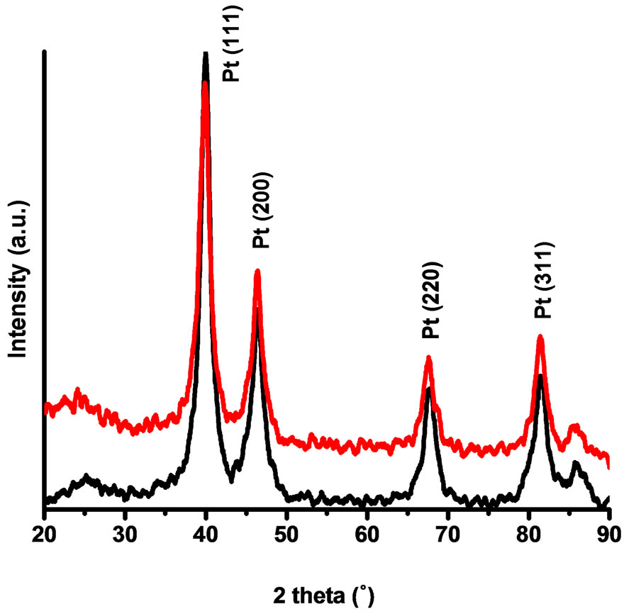
Figure 1. X-ray diffraction patterns of the Vulcan-Pt (black) and Vulcan-Pt-Ce(III) (red) catalysts.
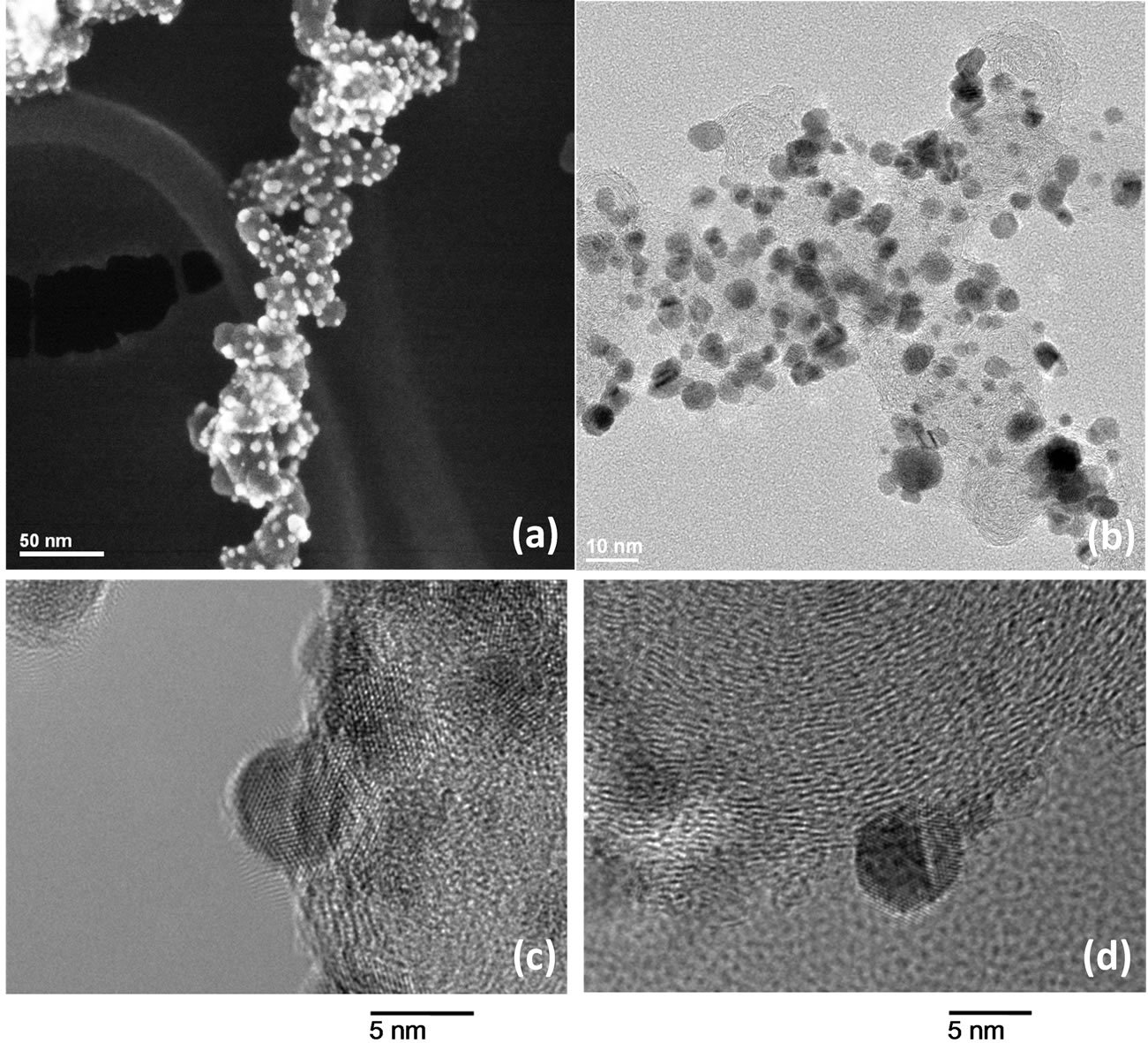
Figure 2. HAADF-STEM (a) and TEM images of Vulcan-Pt-Ce(III) (b) & (d) and Vulcan-Pt catalysts (c).
reported. The platinum nanoparticles show a very welldefined crystal structure with lattice fringes for the atomic planes visible in both catalytic materials. We also observed that there are some agglomerated particles present in the Vulcan-Pt-Ce(III) doped material that are not present in the Vulcan-Pt catalyst. The presence of Ce is as very well dispersed fine particles and difficult to observe in the STEM or TEM. In Figure 3 we have obtained an Energy-dispersive X-ray spectroscopy (EDS) map of the Vulcan-Pt-Ce(III) to observe the localization of the Pt and the Ce. It is evident from this data that the Ce is randomly dispersed on the Vulcan, typically as particles <1 nm in size and is often co-localized near Pt.
2.3. X-Ray Photoelectron Spectroscopy Characterization
X-ray photoelectron spectroscopy (XPS) spectra were obtained using a PHI 5600ci spectrometer equipped with an Al Kα monochromatic source at a power of 350 W. Pass energy of 58.70 eV was used. All the binding energies reported were corrected fixing the carbon peak (C 1s) at 284.5 eV.
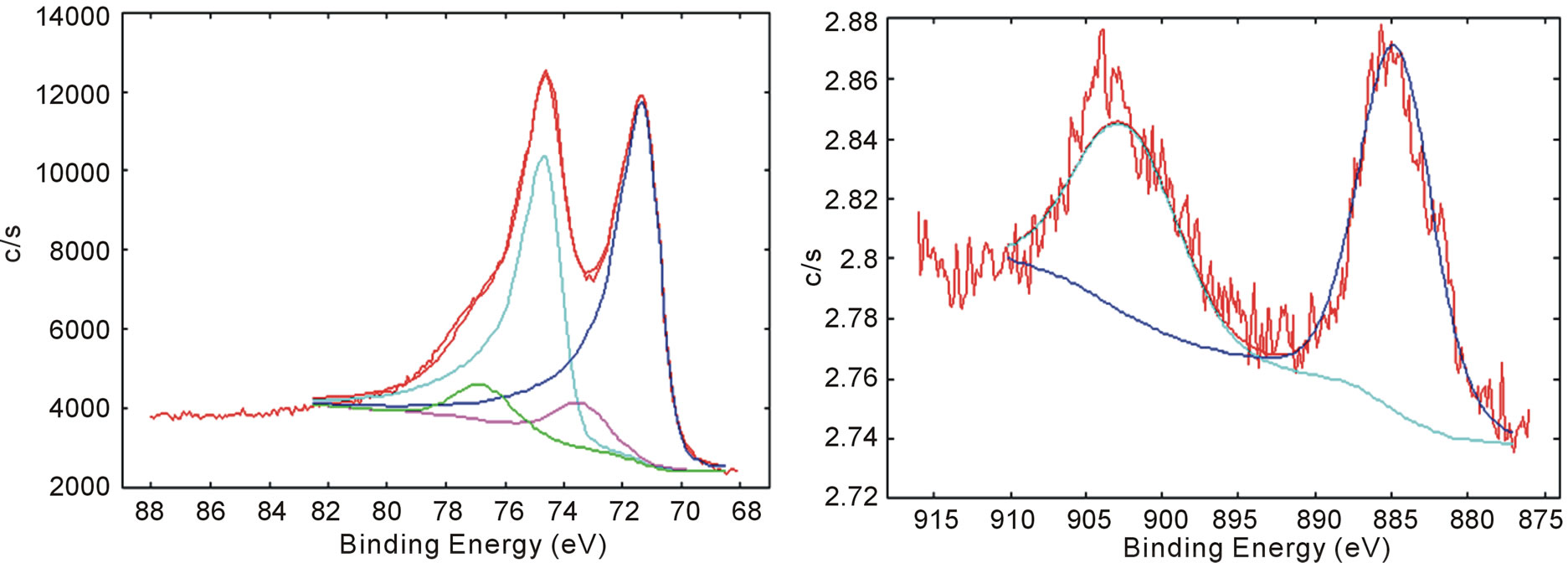
The high-energy resolution XPS spectrum for the core binding energy region of Pt (4f) and Ce (3d) of Vulcan-Pt-Ce doped material are shown in Figures 4(a) and (b) respectively. Deconvolution treatment shows metallic-elemental doblet for platinum 4f peaks at 71.30 eV and 74.63 eV. A second doblet at 73.44 eV and 76.59 eV [29] corroborates that an oxidized platinum specie is present; it was attributed to the presence of PtO2. In Figure 4(b) there is a single doblet for Ce photoelectrons at 885.48 eV and 903.17 eV assigned to Ce(III) [29]. XPS data also matches the NIST table that provides the information that Ce(III) is present in the catalysts [30]. This information confirms that a Ce3+ specie was not oxidized during the impregnation process and it remained in the Vulcan-Pt-Ce(III) doped catalyst.
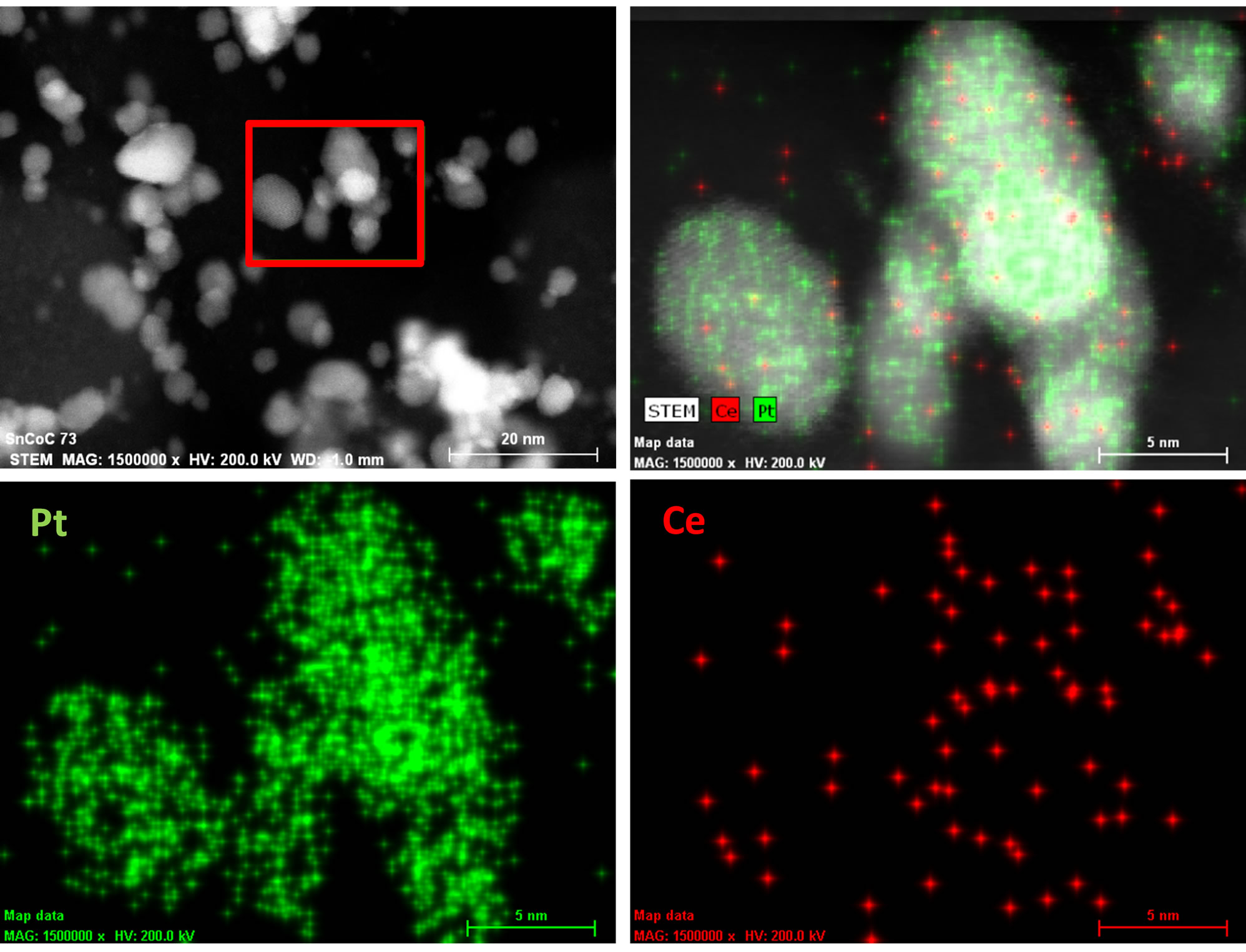
Figure 3. HAADF-STEM of Vulcan-Pt-Ce(III) catalyst with energy dispersive spectroscopy (EDS) X-ray fluorescence map of Pt and Ce speciation.
 (a) (b)
Figure 4. Curve-fitted high-resolution X-ray photoelectron spectroscopy spectra for the (a) Pt 4f and (b) Ce 3d binding energy regions for Vulcan-Pt-Ce(III) catalyst.
3. Electrode Preparation and Electrochemical Study in Half Cell
For the electrochemical study in half cell, a three conventional electrode system was used with a Ag/AgCl reference electrode, a platinum wire as a counter electrode and a glassy carbon (GC) electrode from (Bio Analytical Systems-BAS) as the working electrode. All the electrochemical measurements were carried out using a Potentiostat/Galvanostat model 263A EG&G Instruments, Princeton Applied Research.
The GC electrodes were cleaned until obtained a mirror-like surface by mechanical polishing using alumina powder of different particle sizes: 1.0, 0.3 and 0.05 μm. Residual polishing material was removed from the surface of the electrodes by sonication in a water bath for 15 min. An amount of 1.0 mg of Vulcan-Pt-Ce(III) powder was added to 450 μL of Nafion alcoholic solution (5% w/w). The suspension was agitated in an ultrasonic bath for 40 min followed by stirring for 40 min. Then, 8 μL of the suspension was deposited on the GC electrode surface until it dried.
In order to ensure the purity of Pt particles, an electrochemical CV treatment was done in 0.5 M H2SO4 between −230 and 1100 mV vs. Ag/AgCl, prior to the half-cell and fuel cell experiments.
3.1. Methanol and Ethanol Electrooxidation
The methanol and ethanol oxidation studies were performed using the GC electrode previously modified with Vulcan-Pt and Vulcan-Pt-Ce(III) doped. The catalytic activity toward methanol and ethanol oxidation for the different electrodes was performed using cyclic voltammetry (CV) with a N2-purge and a 1.0 M CH3OH solution in 0.5 M H2SO4 and, for ethanol, a 1.0 M C2H5OH solution in 0.5 M H2SO4 solution. The scan rate was 100 mV/s in the potential range from −0.2 V to 1.0 V vs. Ag/AgCl. The results are shown in Figures 5(a) and (b). The cyclic voltammetry experiments showed higher currents for Vulcan/Pt/Ce catalyst than Pt/Vulcan electrode. The increasing in the oxidation currents is higher when the ethanol was used as a fuel. In this case, there is a shift towards more negative potential of the onset (see Figure 5(b)).
A linear sweep voltammetry (LSV) experiment was carried out using N2 to purge the system in a 1.0M CH3OH in 0.5 M H2SO4 and 1.0 M C2H5OH in 0.5 M H2SO4 solutions. The scan rate was 100 mV/s in the potential range from −0.2 V to 1.0 V vs. Ag/AgCl. Results are shown in Figures 5(c) and (d). In this case, the shift in the onset potential was bigger for the methanol experiment. In both cases, for methanol and ethanol, there is an increasing on the anodic currents for the fuel oxidation when the Vulcan-Pt-Ce(III) catalysts were used.
The electrodes were also tested by chronoamperometry using N2 to purge the system with 0.5 M CH3OH/0.5 M H2SO4 and 1.0 M C2H5OH/0.5 M H2SO4 solutions. This measurement was done using a constant potential of 350 mV vs. Ag/AgCl for 1800s. Figures 5(e) and (f) show a typical current density-time response for methanol and ethanol oxidation. As expected, addition of Ce(III) to Pt/C resulted in higher current densities compared to the Pt/C electrode which is the control. These results support that Ce(III) is contributing to the methanol and ethanol electrooxidation.
4. Single Cell Testing
4.1. MEA Fabrication
A membrane electrode assembly (MEA) was fabricated by placing a Nafion® 117 membrane (Sigma-Aldrich) between Pt-Cerium (0.5 mg/cm2) (anode) catalyst layer
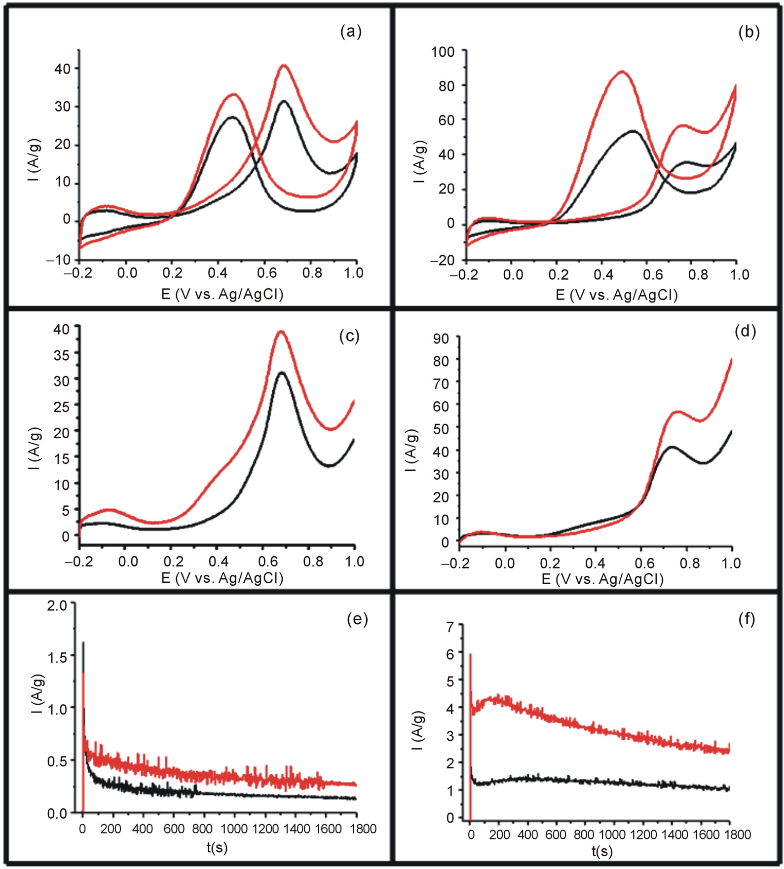
Figure 5. (a) Cyclic voltammetry of catalysts in 0.5 M H2SO4/1M for methanol; (b) Cyclic voltammetry in 0.5 M H2SO4/1M for ethanol; (c) Linear Sweep Voltammetry in 0.5 M H2SO4/1M for methanol; (d) Linear Sweep Voltammetry in 0.5 M H2SO4/1M for ethanol; (e) Chronoamperometric response in 0.5 M H2SO4/1M for ethanol; (f) Chronoamperometric in 0.5 M H2SO4/1M Ethanol for the Vulcan-Pt (black) and Vulcan-Pt-Ce(III) catalyst (red), respectively.
and a Vulcan-40%Pt (0.5 mg/cm2) cathode. The MEA was sandwiched by hot-pressing at 160˚C and 7.5 MPa for 12 min. All experiments, including the electrochemical measurements, were conducted with a MEA sandwiched between two graphite flow-field plates in a Fuel Cell Test Station. All the current-voltage curves (polarization curves) were measured in galvanostatic mode using a HCP-803 with EC-Lab Software (Princeton Applied Research).
4.2. Cyclic Voltammetry
Figure 6 shows the cyclic voltammetry experiment in the fuel cell were the peaks of adsorption and desorption of hydrogen are clearly shown between 0.1 and 0.3 V vs. NHE. The area under the curve for the adsorption and desorption hydrogen peaks is very similar for both catalysts compositions: Vulcan-Pt and Vulcan-Pt-Ce(III) doped. This means that the active surface area of platinum is practically the same in both catalysts. This could be due to the cerium low content in the Vulcan-Pt-Ce(III) which is only 2.3% as determined by X-ray photoelectron spectroscopy.
4.3. Fuel Cell Performance Experiments
Figure 7 shows the polarization curves for the oxidation of hydrogen, methanol and ethanol using the Vulcan-Pt
(black) and the Vulcan-Pt-Ce(III) doped (red) catalysts. The maximum currents obtained in the polarization curves were for the hydrogen oxidation, followed by the methanol. The ethanol oxidation showed the smallest current. This result can be explained by the fact that hydrogen molecule is the easiest to be oxidized due to its chemical simplicity. The complete oxidation of ethanol is not an easy process since there is considerable increment in the number of intermediates related to the 12 electron process involved [31]. The ethanol molecule is the more difficult to be completely oxidized because it has a C-C bond that has to be broken in order to get the final CO2 oxidation product. In the case of the methanol molecule it is not necessary to break any C-C bond; then it is expected that it is easier to oxidize methanol than ethanol. The trend in catalytic currents can be presented as C2H5OH < CH3OH < H2. All this results can also be shown in the power curves, Figure 7.
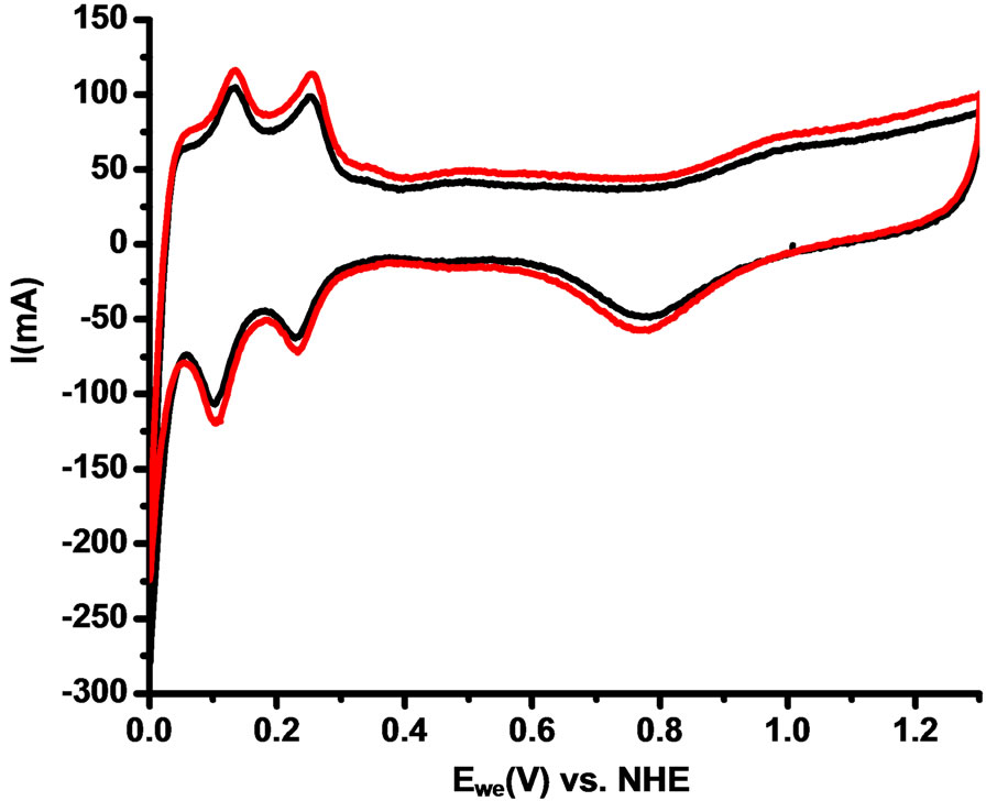
Figure 6. Anodic Cyclic voltammetry of Single Cell of Vulcan-Pt (black) and Vulcan-Pt-Ce(III) doped (red). Fuel cell anode/cathode: N2/H2. Scan rate = 100mV/s; Thumidifier = 75˚C; Tcell = 25˚C; Area of the cell = 5 cm2.
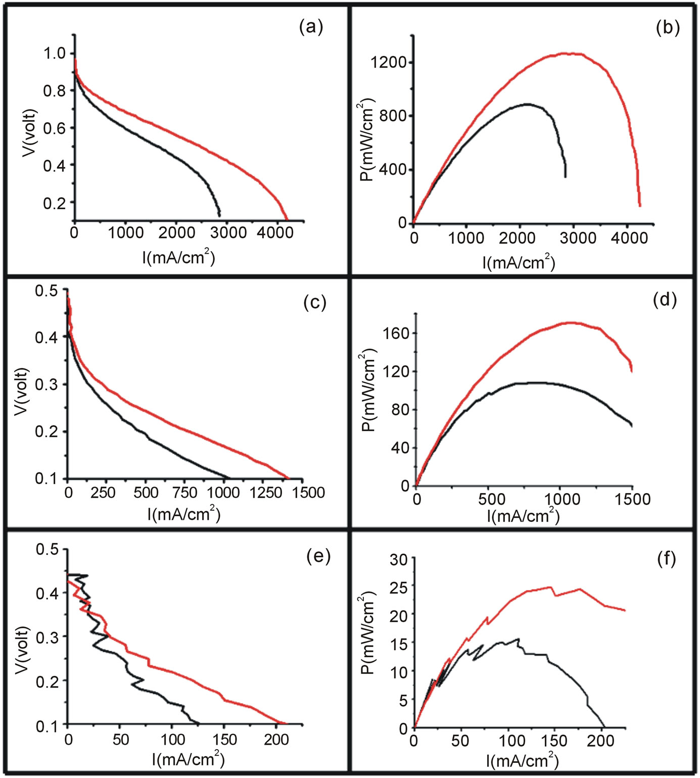
Figure 7. Polarization (left) and power curves (right) for the electrooxidation of H2/O2 ((a) and (b)), 1 M Methanol/O2 ((c) and (d)) and 1M Ethanol/O2 ((e) and (f)) using Vulcan-Pt (black) and Vulcan-Pt-Ce(III) doped (red). The area of the cell is 5 cm2. For cases (a) and (b) the T = 40˚C and for (c) and (d), (e) and (f) T = 90˚C.
5. Conclusion
A Vulcan-Pt-Ce(III) doped catalyst was prepared by a simple and cheap impregnation method using EDTA as chelating agent. The preparation method allows the mass production of the material catalysts without additional significant cost. The final catalyst showed a very good dispersion of the particles in the nanoscale level. Fuel cell polarization and power curves experiments showed that the Vulcan-Pt-Ce doped anode materials exhibited better catalytic activity than the only Vulcan-Pt catalysts for DMFC, DEFC and PEMFC.
6. Acknowledgements
We would like to thank NASA-URC Center of Advanced Nanoscale Materials (NNX10AQ17A) and NSF-NSEC Center for Hierarchical Manufacturing (CHM-CMMI- 053117) for the financial support of this research. CLM is grateful to the Office of Graduate Students and Research (DEGI) from the University of Puerto Rico at Rio Piedras for his scholarship.
REFERENCES
- M. B. Patil, S. L. Bhagat, R. S. Sapkal and V. S. Sapkal, “A Review on the Fuel Cells Development,” Scientific Reviews & Chemical Communications, Vol. 1, No. 1, 2011, pp. 25-41.
- J. Tollefson, “Hydrogen Vehicles: Fuel of the Future?” Nature, Vol. 464, No. 7293, 2010, pp. 1262-1264. http://dx.doi.org/10.1038/4641262a
- S. M. Haile, “Fuel Cell Materials and Components. The Golden Jubilee Issue—Selected Topics in Materials Science and Engineering: Past, Present and Future,” In: S. Suresh, Ed., Acta Materialia, Vol. 51, No. 19, 2003, pp. 5981-6000.
- A. Biyikoglu, “Review of Proton Exchange Membrane Fuel Cell Models,” International Journal of Hydrogen Energy, Vol. 30, No. 11, 2005, pp. 1181-1212. http://dx.doi.org/10.1016/j.ijhydene.2005.05.010
- P. P. Edwards, et al., “Hydrogen and Fuel Cells: Towards a Sustainable Energy Future,” Energy Policy, Vol. 36, No. 12, 2008, pp. 4356-4362. http://dx.doi.org/10.1016/j.enpol.2008.09.036
- S. Rousseau, et al., “Direct Ethanol Fuel Cell (DEFC): Electrical Performances and Reaction Products Distribution under Operating Conditions with Different PlatinumBased Anodes,” Journal of Power Sources, Vol. 158, No. 1, 2006, pp. 18-24. http://dx.doi.org/10.1016/j.jpowsour.2005.08.027
- C. Y. Chen and P. Yang, “Performance of an Air-Breathing Direct Methanol Fuel Cell,” Journal of Power Sources, Vol. 123, No. 1, 2003, pp. 37-42. http://dx.doi.org/10.1016/S0378-7753(03)00434-8
- E. V. Spinacé, A. O. Neto and M. Linardi, “Electro-Oxidation of Methanol and Ethanol Using PtRu/C Electrocatalysts Prepared by Spontaneous Deposition of Platinum on Carbon-Supported Ruthenium Nanoparticles,” Journal of Power Sources, Vol. 129, No. 2, 2004, pp. 121-126. http://dx.doi.org/10.1016/j.jpowsour.2003.11.056
- F. Barbir, “PEM Fuel Cells Theory and Practice,” 2nd Edition, Elsevier, Inc., Amsterdam, 2013.
- M. L. Perry and T. F. Fuller, “A Historical Perspective of Fuel Cell Technology in the 20th Century,” Journal of the Electrochemical Society, Vol. 149, No. 7, 2002, p. S59. http://dx.doi.org/10.1149/1.1488651
- E. Antolini and E. R. Gonzalez, “Alkaline Direct Alcohol Fuel Cells,” Journal of Power Sources, Vol. 195, No. 11, 2010, pp. 3431-3450. http://dx.doi.org/10.1016/j.jpowsour.2009.11.145
- K. Scott, et al., “Performance of a Direct Methanol Alkaline Membrane Fuel Cell,” Journal of Power Sources, Vol. 175, No. 1, 2008, pp. 452-457. http://dx.doi.org/10.1016/j.jpowsour.2007.09.027
- K. Matsuoka, et al., “Alkaline Direct Alcohol Fuel Cells Using an Anion Exchange Membrane,” Journal of Power Sources, Vol. 150, 2005, pp. 27-31. http://dx.doi.org/10.1016/j.jpowsour.2005.02.020
- N. Savage, “Fuel Options: The Ideal Biofuel,” Nature, Vol. 474, No. 7352, 2011, pp. S9-S11. http://dx.doi.org/10.1038/474S09a
- D. J. Díaz, et al., “Novel Nanoscale Ceria-Platinum Composite Electrodes for Direct Alcohol Electro-Oxidation,” Catalysis Letters, Vol. 119, No. 3-4, 2007, pp. 319-326. http://dx.doi.org/10.1007/s10562-007-9238-y
- C. Xu and P. K. Shen, “Novel Pt/CeO2/C Catalysts for Electrooxidation of Alcohols in Alkaline Media,” Chemical Communications (Cambridge, England), Vol. 19, 2004, pp. 2238-2239.
- C. L. Campos, et al., “Preparation and Methanol Oxidation Catalysis of Pt-CeO2 Electrode,” Journal of Electroanalytical Chemistry, Vol. 581, No. 2, 2005, pp. 206-215. http://dx.doi.org/10.1016/j.jelechem.2005.04.002
- C. Xu and P. K. Shen, “Electrochamical Oxidation of Ethanol on Pt-CeO2/C Catalysts,” Journal of Power Sources, Vol. 142, No. 1-2, 2005, pp. 27-29. http://dx.doi.org/10.1016/j.jpowsour.2004.10.017
- X. Feng, Y. Shi and H. Zhou, “Electrocatalytic Enhancement of Methanol Oxidation by Adding CeO2 Nanoparticle on Porous Electrode,” Journal of Rare Earths, Vol. 30, No. 1, 2012, pp. 29-33. http://dx.doi.org/10.1016/S1002-0721(10)60633-3
- E. You, R. Guzman-Blas, E. Nicolau, M. A. Scibioh, C. F. Karanikas, J. J. Watkins and C. R. Cabrera, “Co-Deposition of Pt and Ceria Anode Catalysts in Supercritical Carbon Dioxide for Direct Methanol Fuel Cell Applications,” Electrochimica Acta, Vol. 75, 2012, pp. 191-200. http://dx.doi.org/10.1016/j.electacta.2012.04.091
- C. F. Xu, et al., “Revised Phase Diagram for the Nd-Pt System from 35 to 85 at% Platinum,” Journal of Applied Crystallography, Vol. 43, No. 1, 2010, pp. 33-37. http://dx.doi.org/10.1107/S0021889809050936
- A. Janghorban, et al., “The Phase Diagram of the Ce-Pt System,” Intermetallics, Vol. 18, No. 11, 2010, pp. 2208- 2218. http://dx.doi.org/10.1016/j.intermet.2010.07.012
- C. He, “Evaluation of Platinum-Based Catalysts for Methanol Electro-Oxidation in Phosphoric Acid Electrolyte,” Journal of the Electrochemical Society, Vol. 144, No. 3, 1997, p. 970. http://dx.doi.org/10.1149/1.1837515
- J. W. Guo, et al., “Development of PtRu-CeO2/C Anode Electrocatalyst for Direct Methanol Fuel Cells,” Journal of Power Sources, Vol. 156, No. 2, 2006, pp. 345-354. http://dx.doi.org/10.1016/j.jpowsour.2005.05.093
- T. C. Deivaraj and J. Y. Lee, “Preparation of CarbonSupported PtRu Nanoparticles for Direct Methanol Fuel Cell Applications—A Comparative Study,” Journal of Power Sources, Vol. 142, No. 1-2, 2005, pp. 43-49. http://dx.doi.org/10.1016/j.jpowsour.2004.10.010
- D. Santiago, et al., “Platinum Electrodeposition at High Surface Area Carbon Vulcan-XC-72R Material Using a Rotating Disk-Slurry Electrode Technique,” Journal of the Electrochemical Society, Vol. 157, No. 12, 2010, p. F189. http://dx.doi.org/10.1149/1.3489948
- A. Ignaszak, S. Ye and E. Gyenge, “A Study of the Catalytic Interface for O2 Electroreduction on Pt: The Interaction between Carbon Support Meso/Microstructure and Ionomer (Nafion) Distribution,” The Journal of Physical Chemistry C, Vol. 113, No. 1, 2009, pp. 298-307. http://dx.doi.org/10.1021/jp8060398
- K. Wikander, et al., “On the Influence of Pt Particle Size on the PEMFC Cathode Performance,” Electrochimica Acta, Vol. 52, No. 24, 2007, pp. 6848-6855. http://dx.doi.org/10.1016/j.electacta.2007.04.106
- F. Zhang, et al., “Cerium Oxidation State in Ceria Nanoparticles Studied with X-Ray Photoelectron Spectroscopy and Absorption near Edge Spectroscopy,” Surface Science, Vol. 563, No. 1-3, 2004, pp. 74-82. http://dx.doi.org/10.1016/j.susc.2004.05.138
- G. Praline, B. E. Koel, R. L. Hance and H. I. Lee, “X-Ray Photoelectron Study of the Reaction of Oxygen with Cerium,” Journal of Electron Spectroscopy and Related Phenomena, Vol. 21, No. 1, 1980, pp. 17-30. http://dx.doi.org/10.1016/0368-2048(80)85034-1
- J. Mann, N. Yao and A. B. Bocarsly, “Characterization and Analysis of New Catalysts for a Direct Ethanol Fuel Cell,” Langmuir, Vol. 22, No. 25, 2006, pp. 10432- 10436. http://dx.doi.org/10.1021/la061200c
NOTES
*Corresponding author.