Energy and Power Engineering
Vol.07 No.03(2015), Article ID:54659,7 pages
10.4236/epe.2015.73006
Analysis of the Harmonic Response of a Modulation Permanent Magnetic Transmission Equipment Based on ANSYS
Zhiping Zeng1, Jun Li1, Shiyi Zhang2, Yintao Hong1, Yaohong Wang1
1School of Mechatronics & Automotive Engineering, Chongqing Jiaotong University, Chongqing, China
2School of Marine Navigation, Chongqing Jiaotong University, Chongqing, China
Email: zip_zeng@126.com
Copyright © 2015 by authors and Scientific Research Publishing Inc.
This work is licensed under the Creative Commons Attribution International License (CC BY).
http://creativecommons.org/licenses/by/4.0/


Received 21 February 2015; accepted 10 March 2015; published 16 March 2015
ABSTRACT
This paper analyzes the structure and transmission principles of a modulation permanent magnet gear transmission. Its 3D data model is built based on the known optimized parameters from research team. Its structure of the harmonic response is analyzed and discussed under the software ANSYS. The displacement response and the initial 6 order response frequency and phase angle are obtained. The change rule of these responses is known under the forced vibration.
Keywords:
Magnetic Field Modulation, Permanent Magnetic Transmission, ANSYS, Harmonic Response Analysis

1. Introduction
The traditional transmission method is the transmission of contacting with gears directly. It is designed based on the dynamics, hydraulics, pneumatics and mechanical transmission theory. Due to the problems of low transmission accuracy, friction loss, vibration, noise, energy loss of the action valve and many other flaws, transmission accuracy and efficiency are affected seriously [1] -[5] . In recent years, with the development of transmission method based on the electromagnetic theory, the transmission of no contact, low noise, and low loss has presented. It has been a researching focus [6] -[8] . At present, the research of magnetic gears is basically researches on its static characteristics and its dynamic characteristics have rarely been studied, however, in terms of permanent magnet transmission, the dynamic characteristics are important characteristics [9] [10] . In this paper, a permanent magnet transmission mechanism within a magnetic field modulation is designed and its structure, transmission principle and harmonic response are discussed, analyzed and optimized.
According to the theory of classical mechanics, the general equation of object dynamics [11] is:
 (1)
(1)
where: [M] is mass matrix, [C] is damping matrix, [K] is stiffness matrix,  is force vector, {x} is displacement vector,
  is velocity vector,
  is acceleration vector.
In harmonic response analysis,  is:
is:
 (2)
(2)
The harmonic response analysis is an analysis of the steady vibration of a structure or system under sinusoidal excitation; that’s forced vibration analysis. It can calculate the displacement response amplitude, frequency and phase. It can also do some optimization and improvement on transmission.
2. The Working Principle and Structure of the Magnetic Field Modulation Permanent Magnet Gear
The magnetic field modulation technique is based on the basic structure of the internal mesh permanent magnetic gear, which can modulate the permanent magnetic field to achieve the goal of non-contact transmission [12] . Its structure is shown in Figure 1. The structure of magnetic field modulation permanent magnet gear is studied in this paper.
In the structure, the internal mesh gear mainly includes:
1) A high-speed internal rotor which consists of internal rotor permanent magnet and the inner yoke.
2) A low-speed external rotor which consists of external rotor permanent magnet and the outer yoke.
3) The adjustable magnetic interleaved ring which consists of high permeability material and non-magnetic materials. Its function is modulation magnetic field of the inside and outside rotor.
4) The inner and outer layers are a air gap between the adjacent rotors. Its assembly structure is shown in Figure 2.
According to the theory of electromagnetic field, in the modulation permanent magnet transmission after modulated the magnetic field, the inside and outside permanent magnet ring will produce a space magnetic flux density harmonics and the magnetic flux density harmonic number is [13] :
 (3)
(3)
where: p is the number of pole pairs of rotor permanent magnet, ns is the number of pole blocks of magnetic ring tone.
The angular velocity of space magnetic flux density harmonics is:
 (4)
(4)
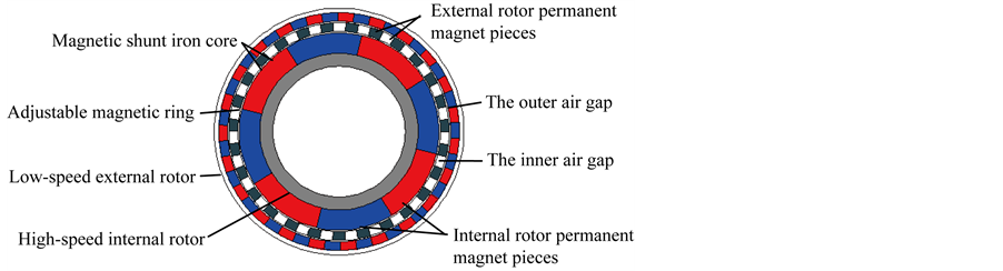
Figure 1. The structure of modulation permanent magnet gear.

Figure 2. An assembly structure of magnetic field modulation permanent magnet gear.
where:  is the speed of inner rotor permanent magnetic loop,
  is the speed of adjustable magnetic ring.
In the structure the modulation magnetic ring is fixed, the internal and external permanent magnet ring rotates so as to achieve torque transmission. Therefore, in the formula (4) , the transmission ratio of permanent magnet gear equipment is:
 (5)
(5)
where: the negative “−” represents that the rotation direction of internal and external permanent magnet rotors is opposite. nout is the number of pole pairs of external permanent magnet ring, nin is the number of pole pairs of internal permanent magnet ring. According to the transmission ratio formula (5), we can know that the transmission ratio of equipment only related to the number of pole pairs of inside and outside permanent magnet ring, but not to the number of pole plates of adjustable magnetic ring.
3. The Model of Modulation Permanent Magnetic Transmission
3.1. Material Properties
Permanent magnet material is NdFeB, which is the linear demagnetization curve (NdFe30). The main parameters and constant parameters are shown in Table 1 [14] . In addition, the yoke part of internal high-speed rotor and external low-speed rotor are structural steel. Its modulus of elasticity is E = 206 Gpa, Poisson ratio is μ = 0.28, density is DENS = 7850 kg/m3.
3.2. Permanent Magnet Gear Finite Element Model
The main structural parameters of finite element model of the gear transmission are selected from the optimized parameter data by research team designing shown as Table 2.
According to Table 2 and the structure parameters of permanent magnet gear and formula (5), we can get the transmission ratio is 5.75. In order to simplify the model without affecting the accuracy of model, we omitted some subordinate structural parameters, such as structure smoothing and rounding. The interference checking on it is completed. Then the model is been imported into ANSYS. The established finite element model is shown in Figure 3, in which the microstructure of the adjustable magnetic ring can be seen in Figure 4 (the microstructure of contact region II).
3.3. Set the Contact Options
Due to using the fixed adjustable magnetic ring, the internal and external permanent magnet ring rotate to transmit the torsion. The inner yoke of high speed inner rotor and inner ring permanent magnet piece are overall connected as a part as well as the external yoke of low speed external rotor and external ring permanent magnet piece. Because of the action of magnetic field force, the structure between the adjustable magnetic ring and the inner ring permanent magnet piece as well as the adjustable magnetic ring and external ring permanent magnet piece becomes a non-contact structure. So the contact type of the contact region I and IV is chosen as “bonded” and contact region II and III is chosen as “frictionless”.
Then outline shape of this structure is simple and it fits the adaptive mesh techniques. We choose tetrahedron as mesh type and mesh size is from “Sizing―Relevance Center―Fine”. The final geometry mesh model is shown as Figure 5. The micro-structure of the contact region II in four contact regions is shown as 5, in which we can observe the micro-structure of adjustable magnetic ring.

Table 1. The parameters of permanent magnet materials.
Table 2. The structure parameters of modulated permanent magnet gear.
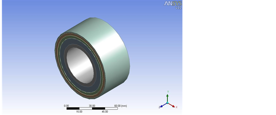
Figure 3. The finite element model of modulated permanent magnet gear.
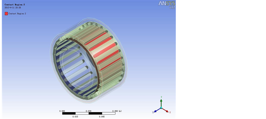
Figure 4. The micro-structure of contact region II.
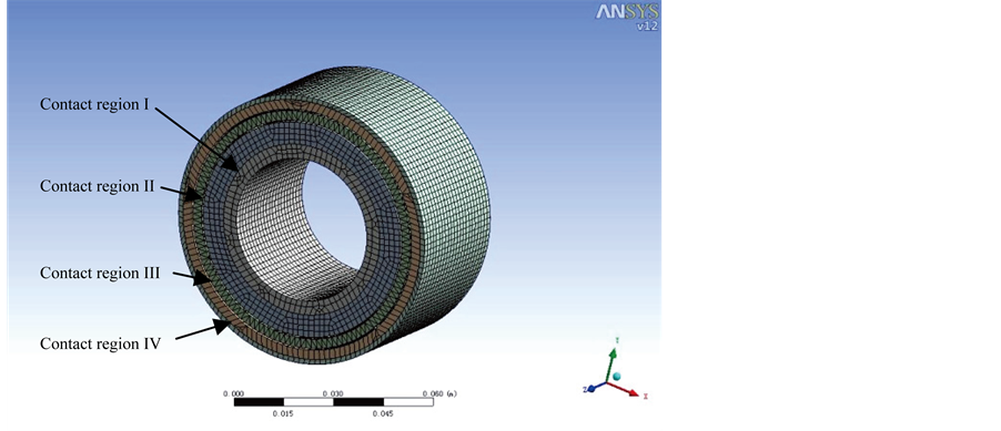
Figure 5. Geometry mesh model.
3.4. Loads and Constraints
The two end planes of the adjustable magnetic ring are restricted rigidly. In the overall frame of axes, the freedom of adjustable magnetic ring is ensured as zero, that is Ux = 0, Uy = 0, Uz = 0. The definite function torsion is acted on the high speed inner rotor, which is the inner yoke surface. It is shown in Figure 6.
4. Analysis of the Results
According to the related parameters, we can obtain the modal responses of the structure. Because the object of actual analysis is an infinite dimension, so its modality has infinite order, but the frequency of the load which acted on the gears is generally lower. The lower order modality plays a great role in the gear vibration, but higher order modality has a little effect on the gear vibration. Based on these reasons, in this paper we choose the initial six modality of vibration to analyze. The value of modal frequency is shown in Table 3.
Figure 7 is the first-order modal displacement response nephogram. According to it, we can know the minimum of the displacement response amplitude is 0.012971 mm, the maximum is 0.024501 mm. The first-order modality is the fundamental frequency modality of the structure, which has a great effect on the actual vibration of the structure. After analyzing and comparing of the initial six order modal displacement response amplitude, we can get that the maximum of the displacement response amplitude is the maximum displacement of the first-order modality (0.024501 mm), and the maximum displacement response amplitude is smaller than the fit clearance of inner and external ring of the permanent magnet gear transmission. Therefore when it operates the vibration of rotors is lowest and almost without noise. The structure fits the design requirements and technology demands of permanent magnet gear transmission. It can ensure the system running smoothly under the sinusoidal excitation and vibrating lower.
5. Conclusion
The harmonic response analysis can be used to determine the steady state response of a linear structure which is
Table 3. The frequency of the initial six modalities.
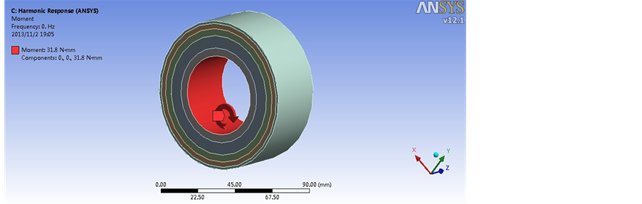
Figure 6. Applied torque.
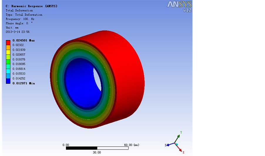
Figure 7. The nephogram of displacement response.
under a changed load by the harmonic rules. In this paper, the harmonic response of a modulation NdFeB permanent magnetic transmission equipment is analyzed and its response change regularity. The maximum displacement response amplitude of the first-order modality is maximum in the entire frequency. It is 0.024501 mm and the maximum displacement response amplitude is smaller than the fit clearance of inner and external ring of the permanent magnet gear transmission. In design, according to the response change regularity, designer can better analyze the stress which corresponds to the peak frequency and predicts the operating stability and continuous dynamic of the system. Thus, we can judge the system whether it will be non-effectiveness which is caused by resonance, fatigue or other forced vibration in operation. So in practical design or application, we need to try to control the first-order modal displacement response amplitude as much as possible so that the equipment and operation system can be ensured to have better reliability and stability.
Acknowledgements
This project is supported by National Natural Science Foundation of China (No. 51305472), Natural Science Foundation of Chongqing CSTC, China (CSTC2013yykfB0184) and the Postgraduate Education Innovation Foundation of Chongqing Jiaotong University under Grant 20120108.
References
- Wang, H.-S., Hou, Y.-P. and Cheng, S.-K. (2008) Development and Prospect of Non-Contact Permanent Magnetic Gear Transmission. MEMS, 02, 71-73.
- Zhang, J.-T. and Xia, D. (2005) Research on the Transmission Characteristic of a Magnetic Gear. Machinery Design & Manufacture, 05, 69-70.
- Yang, C.J. and Gu, H.W. (2008) Current Situation of the Permanent Magnetic Drive Technology and Its Prospect. Journal of Mechanical Transmission, 32, 1-5.
- Liu, X.H. (2008) Design and Research on a Novel Field Modulated Magnetic Gear. Shanghai University, Shanghai.
- Nagrial, M.H., Rizk, J. and Hellany, A. (2007) Design and Development of Magnetic Torque Couplers and Magnetic Gears. International Conference on Electrical Engineering, 11-12 April 2007, 1-5.
- Wang, J.L. and Liu, Q.F. (2010) The Principle and Application of Magnetic Gear Transmission. Journal of Mechanical Transmission, 05, 29-32.
- Mezani, S., Atallah, K. and Howe, D. (2006) A High-Performance Axial-Field Magnetic Gear. Journal of Applied Physics, 99, 08R303-08R303-3. http://dx.doi.org/10.1063/1.2158966
- Madawala, U.K. and Boys, J.T. (2005) Magnetic Field Analysis of an Ironless Brushless DC Machine. IEEE Transactions on Magnetics, 41, 2384-2390.
- Rasmussen, P.O., Andersen, T.O., Jorgensen, F.T. and Nidsen, O. (2005) Development of a High Performance Magnetic Gear. IEEE Transactions on Industry Applications, 41, 764-770.
- Bao, G.Q., Liu, X.H. and Mao, K.F. (2011) Charcteristics of Field Modulated Magnetic Gear in Wind Turbine System. Journal of Agricultural Machinery, 42, 116-120.
- Chen, Y.X. and Chen, L. (2012) Proficient in ANSYS Workbench Engineering Application Case. Publishing House of Electronics Industry, Beijing.
- Ning, W.F. (2012) Design Research on the Magnetic Field Modulated Concentric Gear. Lanzhou University of Technology, Lanzhou.
- Liu, J.C., Cao, J.Y. and Liu, Y. (2012) Analysis on the Transmission Characteristics of Permanent Magnetic Gears. Journal of Mechanical Transmission, 36, 9-13.
- Ge, Y.J., Xin, Q. and Nie, C.Y. (2012) Research on the Relationship of the Field Modulated Permanent Magnetic Gear Structural Parameters and Its Torque. Journal of Mechanical Transmission, 36, 5-8.