Energy and Power Engineering
Vol.6 No.1(2014), Article ID:42281,9 pages DOI:10.4236/epe.2014.61001
Performance of PSS to Damp Power Oscillations Caused by an HVDC Link in AC-DC Power System
1Department of Electrical Engineering, L2GEGI Laboratory, Ibn Khaldoun University, Tiaret, Algeria
2Department of Electrical Engineering, ICEPS Laboratory, Djillali Liabes University, Sidi Bel Abbes, Algeria
Email: benasla.mokhtar@yahoo.fr
Received December 10, 2013; revised January 10, 2014; accepted January 17, 2014
ABSTRACT
HVDC (High Voltage Direct Current) systems are increasingly being applied to improve power system operation and controllability. However, inappropriate setting of HVDC controller may have a detriment effect on the system performance. Generally, PSS (Power System Stabilizer) is known as a simple concept, easy to perform, and computationally effective to enhance damping of power system oscillations through excitation control of synchronous generator. This paper examines the effectiveness of the PSS to enhance the dynamic performance of AC-DC power systems and to compensate the negative damping of HVDC system. The dynamic performance is evaluated by examining the system response to various disturbances. In order to ensure the reliability of the simulation test results as well as the performance of the PSS, detailed HVDC modeling is adopted using SimPowerSystems toolbox in the MATLAB, and some important conclusions are drawn.
Keywords:HVDC; PSS; AC-DC Power Systems; Power System Stability
1. Introduction
The development of power systems follows the requirements to transmit power from generation to the consumers. With an increased demand for energy and the construction of new generation plants, the size and complexity of power systems have grown. With an increasing size of the interconnected systems, the technical and economical advantages diminish. This is related to problems regarding load flow, power oscillations and voltage quality. If power is to be transmitted through the interconnected system over longer distances, transmission needs to be supported [1]. HVDC (High Voltage Direct Current) provides the necessary features to avoid technical problems in the power systems, and it increases the transmission capacity and system stability very efficiently. HVDC can also be applied as a hybrid AC-DC solution in synchronous AC systems either as Back-to-Back for grid power flow control (elimination of congestion and loop flows) or as long-distance point-to-point transmission [2]. However, it has caused some problems in the applications [3,4]. For example, in 1977, the Square Butter HVDC system in USA suffered from the subsynchronous oscillation (SSO). The following studies showed that this dynamic instable phenomenon occurred at the side of the HVDC rectifier, and was mostly attributed to the negative damping torque caused by the inappropriate control of a HVDC link [5]. Since then, many analog simulators and computer based simulation programs have been developed to study the SSO caused by HVDC links [5].
So, it is necessary to study how to decouple the interactions and solve the coordinate problems of the controllers. Both the excitation control of generators and the HVDC are important to improve the stability of power systems and restrain the low frequency oscillation.
Conventional power systems are known to be subject to low frequency oscillations and due to the complexity and increasing dimensions associated with modern power systems. Several modes of oscillations have appeared in the dynamic response of the power system. If these oscillations persist, they can present limitation on power system performance.
Power system stabilizers (PSSs) are used as an effective way to enhance the damping of these oscillations [6].
The use of PSS in power system has been both economical and successful in improving the power system stability, and is expected to be installed on many generators connected to the system [7].
With the growing use of the HVDC technology in China power grid, unfortunately only a few of the generators in the China System are provided with power system stabilizers (PSS). The combination of this condition and the radial structure is likely the cause of poorly damped oscillations in central China [8]. In this paper a detailed study has been carried out in Sim Power Systems toolbox in the MATLAB environment to examine the effectiveness of the PSS to enhance the dynamic performance of AC-DC power systems and to compensate the negative damping of HVDC system.
2. Model Description
2.1. Test Power System
Figure 1 shows a model configuration of electric power systems with DC transmission. The model consists of single synchronous generator-infinite bus system and one DC link which is connected onto the bus of synchronous generator. The simple configuration of Figure 1 is based on a practical power system in Japan [9]. The mechanical power supplied by turbine is considered invariant for the duration of transient simulation runs.
2.2. HVDC Link
The HVDC considered in this paper (Figure 2) is of conventional type based on the CIGRE benchmark system [10,11]. The rectifier and the inverter are 12-pulse converters using two 6-pulse thyristor bridges connected in series. The transformer tap changers are not simulated
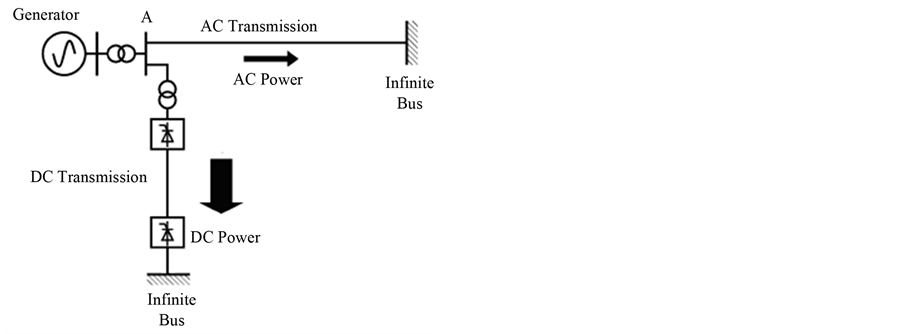
Figure 1. Electric power system with DC transmission.
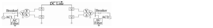
Figure 2. HVDC system.
and fixed taps are assumed. Reactive power required by the converters is provided by a set of capacitor banks plus 11th, 13th and high pass filters on each side. A series reactor is also included between the two HVDC stations to make the DC current smooth.
By controlling the firing angle for the rectifier αRec, the power through the HVDC is controlled.
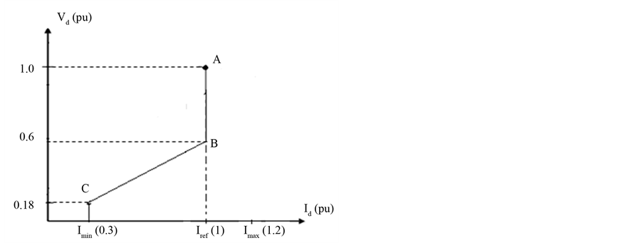
The current controller is shown in Figure 3. The limited current Iord reference is generated using the Voltage Dependent Current Limit (VDCL) unit. These units provide current reference values during steady and transient state conditions respectively. In order to maintain the operation of the AC system, VDCL limits the current in the DC line, if the DC voltage decreases, e.g. due to an AC system disturbance [10]. When normal operation has returned and the DC voltage recovered, current returns to its steady-state level Iref (1 pu).
3. Automatic Voltage Regulator (AVR)
The principal function of the excitation system is to furnish dc power (direct current and voltage) to the generator field, creating the magnetic field. The excitation system also provides control and protective equipment that regulates the generator electrical output.
One desirable characteristic of an excitation system is its ability to produce high levels of excitation voltage (ceiling) very rapidly, following a change in terminal voltage.
The automatic voltage regulator (AVR) provides for control of the terminal voltage of the generator by changing the generator field voltage to make the system more transient stable during disturbances.
There are a variety of designs for the AVR, including various means of ensuring stable response to transient changes in terminal voltage.
Figure 4 shows The IEEE AVR Type I [12]. Where Vt is the generator terminal voltage or a remote-bus regulated voltage and Se is the ceiling function.
The parameters of this AVR are shown in Appendix.
The contribution of the AVR on the transient stability is shown by the following simulations:
At time t = 1 s a three-phase to ground fault of 130 ms duration occurs at the AC transmission line near bus A as shown in Figure 1.
Figure 5 shows the transient responses for this fault condition. Comparison of results between both cases with AVR and without AVR for the similar nature and

Figure 3. Current controller.
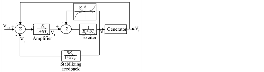
Figure 4. Automatic voltage regulator IEEE type 1.
duration of faults indicate:
It can be observed that, the system becomes unstable when the AVR is not in operation (without AVR). This is due to the poor damping of the oscillations. However, When the AVR is applied; the system becomes more oscillatory but remains stable.
The mighty action of the AVR to improve the transient stability has an important negative contribution unfortunately on the small-signal stability of the system (Figure 5(c)). However the current of excitation cannot immediately change because of the time constants of the regulator.
Figure 6 shows the adverse effect of the AVR on system oscillations. This type of oscillation is called localmode oscillation and its behavior is mainly limited to the local area in the vicinity of the power plant, and it seldom influences the rest of the system. It has been known that the local oscillation is likely to occur when power is transmitted over long-distance transmission lines from a power plant at a remote location [7].
This category of oscillations can exist simultaneously with another mode of oscillations as the control mode oscillations, this type of oscillations are associated with the controls of generating units and other equipment. Poorly tuned controls of excitation systems, prime movers, static var compensators, and HVDC converters are the usual causes of instability of control modes [13].
The performance of power systems decrease with the size and complexity of the networks. Should power be transmitted through the interconnected system over longer distances, transmission needs to be supported. The choice between transmission alternatives is made on the basis of cost and controllability. The original justification for HVDC systems was its lower cost for long electrical distances, (i.e. the favorable case for the local-mode oscillations).
It is well documented that inappropriate setting of HVDC controller could cause dynamic instability of an AC-DC system [5].
Figure 7 shows the negative effect of the HVDC on the system considered in Figure 1. The main reason of the instability caused by the HVDC control system is due to the existence of the negative damping.
These oscillations may sustain and grow to cause system separation if no adequate damping is available.
However, the capability of an HVDC link to rapidly modulate the power flow, in response to control signals such as frequency deviation and rate of change of AC power, has been utilized for some time to improve the dynamic stability of AC-DC systems [14].
The ability to enhance power system stability based on HVDC power modulation depends on several factors including the location of the HVDC link converters, the feedback signal used as input to the control, as well as the internal characteristics of the AC system.
However, The HVDC with classical DC power control even with supplementary damping signal does not contribute to system synchronizing torque and may increase the risk of instability. A good example is the black-outs of the AC-DC system of the western USA in summer ‘96 [15].
HVDC systems were also found to interact adversely with torsional vibrations (the subsynchronous torsional interaction problem), especially when augmented with supplemental modulation controls to damp power swings [13]. Furthermore, the excessive DC modulated power are usually not desired due to the increased reactive power requirements in the inverter side AC system and its effect on voltage level, as well as the possibility of adverse influence on DC recovery and operation performance during the initial stages of system post-fault recovery [4].
4. Power System Stabilizer (PSS)
There are several ways to damp the low-frequency oscillations. Among them, the use of Power System Stabilizer (PSS) is the most effective and robust [6].
A power system stabilizer (PSS) is frequently, but not always, included in an excitation system. It is designed to modulate the AVR input in such a manner as to contribute damping to oscillations. The input to the PSS may be generator rotor speed (∆ω), electrical power (∆P), or other signals [13].
The output signal of the PSS is injected into the summing junction of the exciter block (Figure 8) in the generator to damp out low frequency oscillations of the

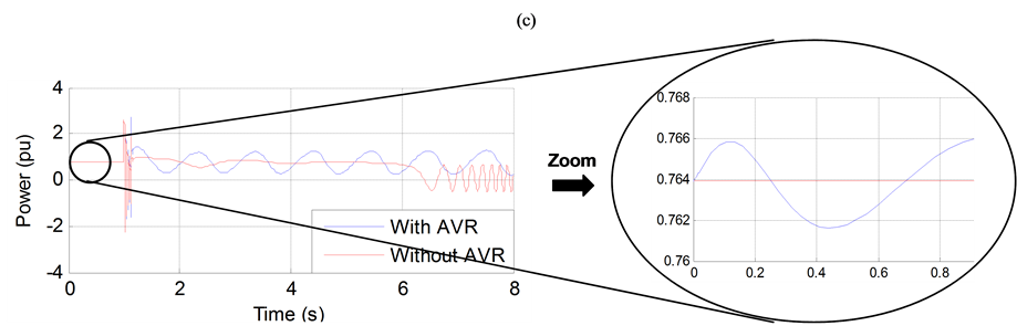
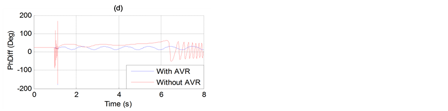
Figure 5. (a) Generator speed. (b) Generator terminal voltage. (c) Generator active power output. (d) Transmission angle (PhDiff) between two ends.

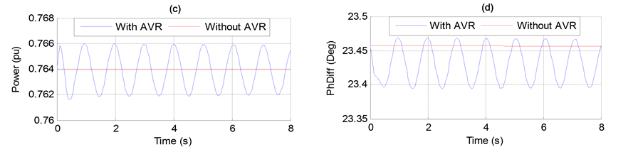
Figure 6. (a) Generator speed. (b) Generator terminal voltage. (c) Generator active power output. (d) Transmission angle (PhDiff) between two ends.

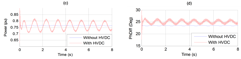
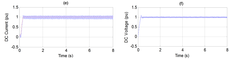

Figure 7. (a) Generator speed. (b) Generator terminal voltage. (c) Generator active power output. (d) Transmission angle (PhDiff) between two ends. (e) DC Current. (f) DC Voltage. (g) DC power transfer (Pdc). (h) Rectifier and inverter firing angle order.
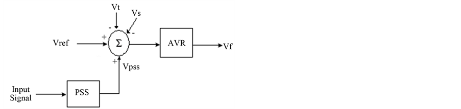
Figure 8. AVR with PSS.
power system. It is the most economical way to mitigate this kind of low frequency oscillations.
Furthermore, PSS design by method of phase compensation is based on knowledge of the physical aspect of power systems, and is more robust and relatively easier than other methods. The input signal of the PSS used in this paper is the electrical power signal. Its block diagram is shown in Figure 9.
The parameters of this PSS are shown in Appendix.
In a multi-machine power system, it is important to determine the best location for the application of power system stabilizers [16]. Several techniques have been proposed in the literature to determine the best location for applying power system stabilizers. Participation factor method is one of the methods in detecting the contribution of various generators in each mode and for suitable location for applying the PSSs. Some authors have proposed sensitivity of PSS effect (SPE) as a measure for determining the suitable location of PSSs [16], so that the dominant generator with the greatest influence on both the power system stability, and the low-frequency oscillation becomes the candidate for PSS installation.
In a AC-DC power system the low-frequency oscillation occurred at the side of the HVDC rectifier [5]. So the generator at the rectifier side is the best location for the application of power system stabilizers.
An appropriate parameter design is very important in order for a PSS to operate effectively. In general, these parameters are set with the single machine infinite bus model. So before deployment in the AC-DC power system, it is worth checking the performance of the PSS in the system without HVDC.
The results of Figure 10 show the effectiveness of the PSS device when added to conventional voltage regulators AVR.
It is clear from these figures that PSS improves the stability performance of the example power system without HVDC, and the low frequency oscillations are significantly damped in comparison to the results without PSS.
The effect of PSS to improve the performance transient stability is shown by simulation a three phase to ground fault (at 1 s) near bus A (Figure 1, without HVDC) of duration 130 ms and 180 s in Figures 11 and 12, respectively.
It can be clearly seen that the PSS enhances the stability performance of the power system. Figure 12(a) gives the variation of generator speed. As can be seen in the figure, the system without PSS falls out of synchronism. However, when the PSS is applied, the system remains stable. Therefore, power system stabilizers (PSSs) are employed to enhance the dynamic and transient performance of power systems.
Once the performance of PSS is evaluated without HVDC, the relevant question is: it is possible to get an effective damping of oscillation modes with the same PSS (with the same parameter setting) if the system is equipped with an HVDC link (Figure 1).
Figure 13 gives a better answer to this question.

Figure 9. Power system stabilizer.
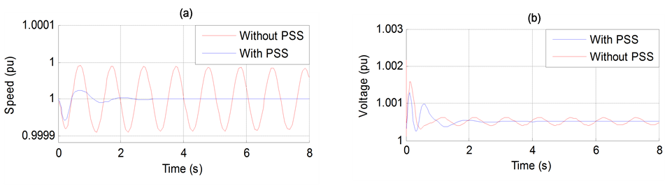

Figure 10. (a) Generator speed. (b) Generator terminal voltage. (c) Generator active power output. (d) Transmission angle (PhDiff) between two ends.
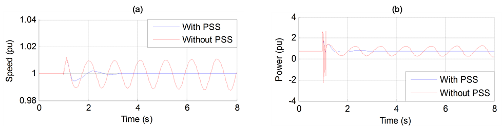
Figure 11. (a) Generator speed. (b) Generator active power output.

Figure 12. (a) Generator speed. (b) Generator active power output.
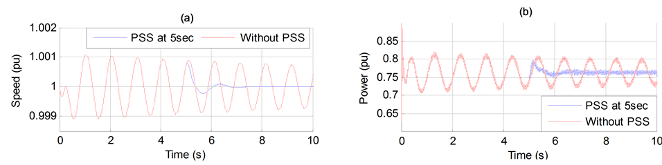
Figure 13. (a) Generator speed. (b) Generator active power output.
It can be seen from this figure that the installation of the PSS (at 5 sec) provides faster response and can enhance the system dynamic performance well and lines can transmit the power stably.
A three-phase to ground fault occurs (at 3s) near bus A (Figure 1) of 130ms duration in order to test the system damping with a short-circuit fault. The simulation results are shown in Figure 14. It is clear from these figures that PSS improves the stability performance of the example power system, and the oscillations are significantly damped in comparison to the results without PSS.
So, the HVDC can be used now to improve the transient stability by modulation of the transmitted active power with an acceptable level of reliability.
5. Conclusions
The steady state and transient simulations show that the HVDC system can cause dynamic instability of an AC-DC power system due to the negative interaction between AC and DC systems and the problem of poor damping. The effectiveness of the application of PSS to compensate the negative damping of HVDC system has been examined by detail simulation. The results show that the PSS improves the stability performance of the example AC-DC power system, and the oscillations are significantly damped.
The research will bring important and significant reference for further operation and stability control of HVDC and AC system. Further research still remained on the topics such as the coordinated control strategy between PSS and HVDC damping modulation for the damping of all the critical modes of the system, best location of the PSS and also the tuning of PSS parameters in multi-machine AC-DC power systems and so on.
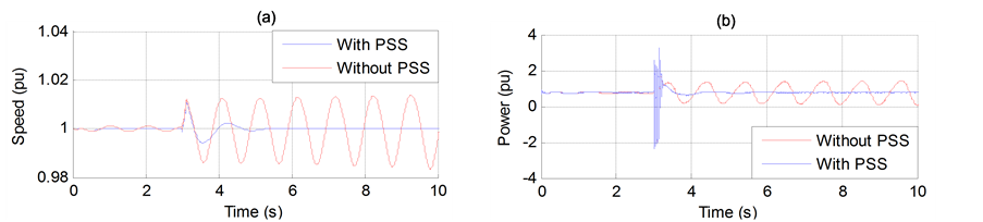

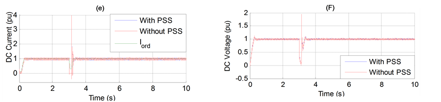
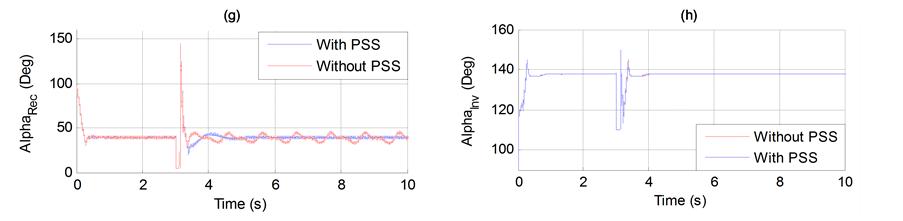
Figure 14. (a) Generator speed. (b) Generator active power output. (c) Generator terminal voltage. (d) Transmission angle (PhDiff) between two ends. (e) DC Current. (f) DC Voltage. (g) Rectifier firing angle order and (h) Inverter firing angle order.
Therefore, the control of HVDC has the potential for future application to power systems.
REFERENCES
- G. Beck, D. Povh, D. Retzmann and E. Teltsch, “Global Blackouts—Lessons Learned,” Power Transmission Division, Siemens AG, 2011.
- W. Breuer, D. Retzmann and K. Uecker, “Highly Efficient Solutions for Smart and Bulk Power Transmission of Green Energy,” Power Transmission Division, Siemens AG, 2011.
- D.-J. Kim, H.-K. Nam and Y.-H. Moon, “A Practical Approach to HVDC System Control for Damping Subsynchronous Oscillation Using the Novel Eigenvalue Analysis Program,” IEEE Transactions on Power Systems, Vol. 22, No. 4, 2007, pp. 1926-1934. http://dx.doi.org/10.1109/TPWRS.2007.907974
- X.-M. Mao, Y. Zhang, L. Guan and X. C. Wu, “Researches on Coordinated Control Strategy for Inter-Area Oscillations in AC/DC Hybrid Grid with Multi-Infeed HVDC,” IEEE/PES Transmission and Distribution Conference & Exhibition: Asia and Pacific, Dalian, 2005, pp. 1-6.
- T. Yu, K. Chan and Z. Ren, “Damping Analysis of Primary and Auxiliary Control of HVDC Systems,” IEEE/ Power Engineering Society General Meeting, Montreal, 2006.
- G. Liu, Z. Xu, Y. Huang and W. Pan, “Analysis of Inter-Area Oscillations in the South China Interconnected Power System,” Electric Power Systems Research, Vol. 70, No. 1, 2004, pp. 38-45.
- A. R. Fereidouni, B. Vahidi, T. Hoseini and M. Tahmasbi, “Improvement of Low Frequency Oscillation Damping by Allocation and Design of Power System Stabilizers in the Multi-Machine Power System,” International Journal of Electrical Power & Energy Systems, Vol. 52, 2013, pp. 207-220.
- K. Högberg, M. Ericsson, A. Kumar, K. Lindén and W. Weibing, “Stability Improvement for Central China System.” library.abb.com/GLOBAL/.../ICPS01Stability.pdf.
- Y. Susuki, T. Hikihara and H. Chiang, “Discontinuous Dynamics of Electric Power System with DC Transmission: A Study on DAE System,” IEEE Transactions on Circuits and Systems, Vol. 55, No. 2, 2008, pp. 697-707.
- V. K. Sood, “HVDC and FACTS Controllers Applications of Static Converters in Power Systems,” Kluwer Academic Publishers, 2004.
- M. Benasla, T. Allaoui, H, Chaib and N. Cherif, “BackUp Protection to Enhance Operation of HVDC System,” The International Conference on Electronics & Oil: From Theory to Applications, Algeria, 2013.
- F. Milano, “Power System Modelling and Scripting,” Springer-Verlag, London, 2010. http://dx.doi.org/10.1007/978-3-642-13669-6
- R. G. Farmer, “Power System Dynamics and Stability,” The Electric Power Engineering Handbook Series, CRC Press LLC, 2001.
- Transmission and Distribution Committee of the IEEE Power Engineering Society, “IEEE Guide for Planning DC Links Terminating at AC Locations Having Low Short-Circuit Capacities,” IEEE Std 1204-1997.
- E. Hammad, “Stability and Control of HVDC and AC Transmissions in Parallel,” IEEE Transactions on Power Delivery, Vol. 14, No. 4, 1999, pp. 1545-1554. http://dx.doi.org/10.1109/61.796252
- Karimpoura, R. Asgharianb and O. P. Malik, “Determination of PSS Location Based on Singular Value Decomposition,” International Journal of Electrical Power & Energy Systems, Vol. 27, No. 8, 2005, pp. 535-541.
Appendix. Parameters of the Power System Used as an Application Example
Generator:
Sn = 2100 MVA, Vn = 13.8 kV, f = 50 Hz, Xd =1.305Xd′ = 0.296 pu, Xd″ = 0.252 pu, Xq = 0.474 pu, Xq″ = 0.243 pu, Xl = 0.18 pu, Tdo′ = 1.01 s, Tdo″ = 0.053 s, Tqo″ = 0.1 s, Ra = 0.0028544 pu, H = 3.7 sExcitation system (AVR):
Ka = 300, Ta = 0.001 s, Ke = 1, Te = 0, Kf = 0.001Tf = 0.1 s.
Power system stabilizer (PSS):
Tw = 1 s, T1 = 0.06 s, T2 = 1 s, T3 = 0 s, T4 = 0 sVs_max = 0.15 pu, Vs_min = −0.15 pu, KPSS = 2.5.
Generator transformer:
2100 MVA, 13.8 kV/500 kV Converters:
Snubber resistance Rs = 5000 Ohms Snubber capacitance Cs = 0.05 µF Ron = 0.01 Ohms, Lon = 0 Forward voltage Vf = 1 V Rectifier: αmin = 5˚, αmax = 145˚.
Inverter: αmin = 110˚, αmax = 150˚.
Converter transformers:
Rectifier Transformer, 500/211.42*2 kV, 1200 MVA;
Inverter Transformer, 211.42*2/500 kV, 1200 MVA.
VDCL characteristic: