Energy and Power Engineering
Vol.5 No.10(2013), Article ID:41185,14 pages DOI:10.4236/epe.2013.510064
Carbon Dioxide Capture and Utilization for Gas Engine
Power and Industrial Systems R&D Center, Toshiba Corporation, Fuchu, Japan
Email: taka.ogawa@toshiba.co.jp
Copyright © 2013 Takashi Ogawa. This is an open access article distributed under the Creative Commons Attribution License, which permits unrestricted use, distribution, and reproduction in any medium, provided the original work is properly cited. In accordance of the Creative Commons Attribution License all Copyrights © 2013 are reserved for SCIRP and the owner of the intellectual property Takashi Ogawa. All Copyright © 2013 are guarded by law and by SCIRP as a guardian.
Received November 2, 2013; revised December 2, 2013; accepted December 9, 2013
Keywords: Carbon Dioxide Capture; Carbon Dioxide Utilization; Carbonate Formation; Gas Engine
ABSTRACT
Sodium glycinate absorption and ethylene carbonate synthesis from a mixture gas of ethylene oxide and carbon dioxide are evaluated as carbon dioxide capture and utilization system for gas engine flue gas. The energy requirement for CO2 capture is estimated at 3.3 GJ/tonne CO2. The ethylene carbonate synthesis utilizes more than 90% of the captured CO2 and supply 2.5 GJ/tonne CO2 of thermal energy, which is 76% of the energy requirement for CO2 capture. The thermal integration of the sodium glycinate absorption and the ethylene carbonate synthesis reduces the energy requirement for CO2 capture from 3.3 GJ/tonne CO2 to 0.8 GJ/tonne CO2. The energy requirement for the CO2 capture is supplied using the steam saturated at 0.78 MPa from the gas engine without its electric power reduction.
1. Introduction
Over the past decade, the global warming resulting from anthropogenic carbon dioxide (CO2) has become one of the most important environmental matters. A quarter of the CO2 emissions all over the world are exhausted from thermal plants. Post-combustion carbon dioxide capture is the technique that can be rapidly and safely employed for substantially reducing carbon dioxide emissions from existing and near future power plants [1]. The captured CO2 is compressed, transported, and stored in depleted oil and gas fields [2].
A gas engine has been used as a combined heat and power system. The flow rate of carbon dioxide in its flue gas is short to carbon capture and storage, especially for transporting and storing captured carbon dioxide. Therefore, plant fertilization at a greenhouse is used to utilize the captured CO2 from a gas engine [3]. However, the plant fertilization needs the large area and is not capable of supplying the heat of CO2 capture.
North reported ethylene carbonate synthesis from dilute CO2 and dilute ethylene oxide uses a gas-phase continuous flow reactor near conditions of ambient temperature and pressure. The synthesis is highly exothermic reaction and the rate of the reaction is high [4]. The ethylene carbonate synthesis from pure CO2 was not estimated using a gas-phase reactor. Weiland reported sodium glycinate can remove CO2 from the flue gas of a coal-fired thermal plant [5]. It was not estimated in the case of the flue gas of a gas engine, whose CO2 concentration is much lower than that of a coal-fired thermal plant.
In this paper, we evaluated sodium glycinate absorption as CO2 capture and ethylene carbonate synthesis as the captured CO2 utilization and heat recovery for a gas engine.
2. Carbon Dioxide Capture and Utilizatio System
2.1. Gas Engine
Table 1 shows the specifications of the KV-18-V gas engine made by Kawasaki Heavy Industries, Ltd [6]. The KV-18-V gas engine has achieved a thermal efficiency of 49% on the basis of lower heating value and provide 7.8 MW of electric power, 2.3 MW of thermal power as steam saturated at 0.78 MPa, and 3.3 MW of thermal power as hot water at 88˚C. The fuel is city gas 13A [7] and the flow rate is 1412 Nm3/h. The flue gas composition and flow rate are estimated under the assumptions; 1) air consists of oxygen (20.95%) and nitrogen (79.05%) [8], 2) the air-to-fuel ratio is 2.2 [9]. Those result in that the flue gas composition is a mixture of CO2 (4.72%), H2O (8.77%), O2 (10.92%), and N2 (75.59%) and the
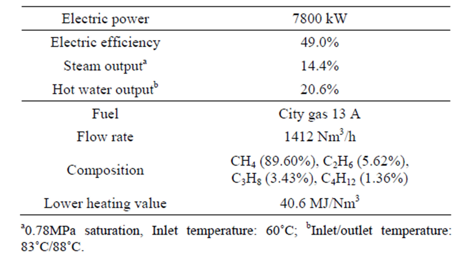
Table 1. Specifications of KV-18-V gas engine.
flow rate of the flue gas is 34,857 Nm3/h.
2.2. Carbon Dioxide Capture System
Figure 1 shows a carbon dioxide capture system. The system consists of an absorber, a rich-lean heat exchanger, a stripper, and a lean cooler. The flue gas enters the bottom of the absorber and an absorbing solvent enters the top of the absorber. The absorbing solvent selectively absorbs CO2 from the flue gas. The CO2 rich solvent from the bottom of the absorber passes through the rich-lean heat exchanger to preheat. The preheated CO2 rich solvent enters at the top of the stripper. Then it is heated by the steam from a reboiler and desorbs CO2. The desorbed CO2 is separated from the steam at the top of the stripper. The CO2 lean solvent from the bottom of the stripper is cooled using the rich-lean heat exchanger and the lean cooler. The cold CO2 lean solvent is recirculated to the top of the absorber.
Table 2 shows the design conditions of the CO2 capture system. The absorbing solvent is 45 wt% Sodium Glycinate. The absorber inlet temperatures of the flue gas and the cold lean solvent are 40˚C. A temperature of approach of 4˚C is chosen for the rich-lean heat exchanger. The absorber and stripper have 18 m and 9 m height beds using Sulzer Mellapak M250.X structured packing, respectively. They are sized for 50% of flood. The operation pressure of the stripper is 200 kPa. The carbon dioxide capture system is simulated using the ProTreat® software (Optimized Gas Treating, Inc.).
2.3. Ethylene Carbonate Synthesis System
Figure 2 shows an ethylene carbonate synthesis system. The ethylene carbonate synthesis system consists of a heat exchanger and a Gibbs reactor, for which the reaction equilibrium is calculated by minimizing the Gibbs free energy at specified temperature and pressure.
An equimolar mixture gas of the captured CO2 and ethylene oxide (EtO) enters the heat exchanger at 40˚C and is preheated. The preheated mixture enters the Gibbs reactor and forms ethylene carbonate (EtCO3) from CO2
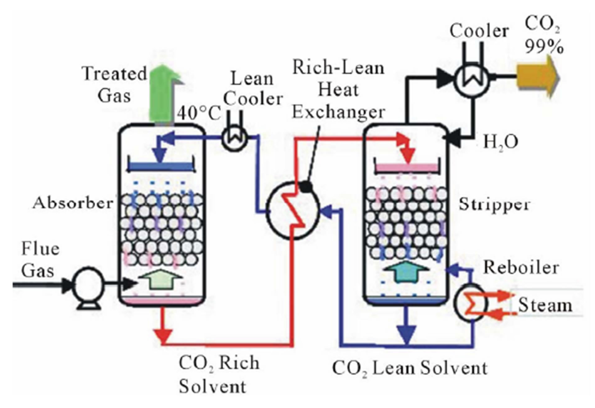
Figure 1. Carbon dioxide capture system.
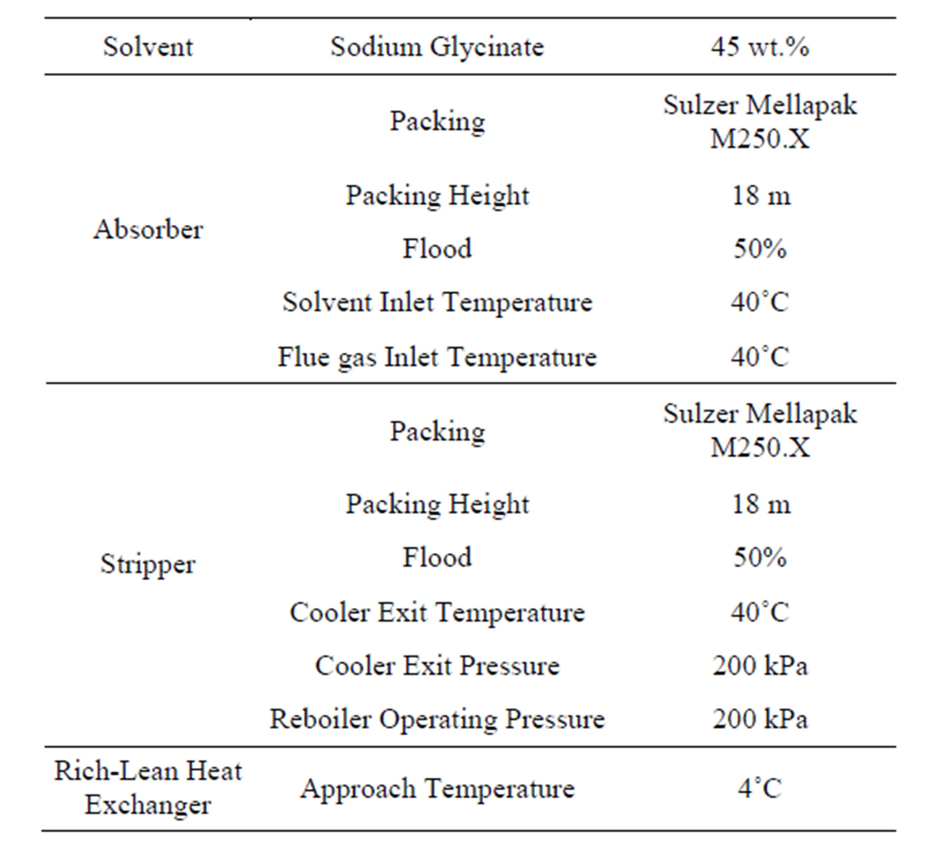
Table 2. Design conditions of CO2 capture system.
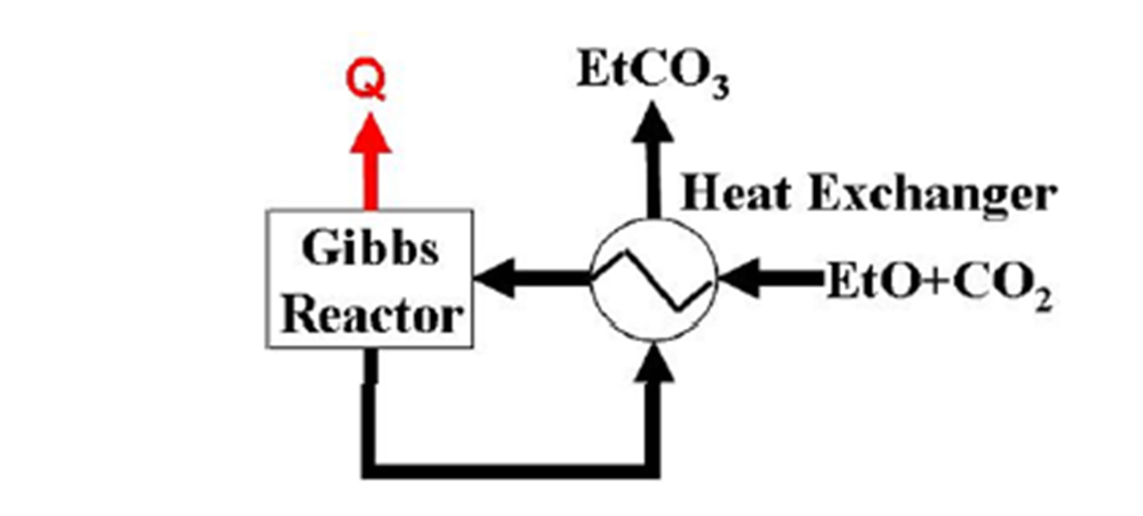
Figure 2. Ethylene carbonate synthesis system.
and ethylene oxide exothermically. The synthesized ethylene carbonate is cooled in the heat exchanger. A temperature of approach of 10˚C is chosen for the heat exchanger. The ethylene carbonate synthesis system is simulated using the VMGSim® software (Virtual Material Group Inc.) with Advanced Peng-Robinson property package. The temperature of ethylene oxide at the heat exchanger exit is higher than 40˚C, which is higher than the melting point of ethylene carbonate (34˚C - 37˚C).
3. Results and Discussion
3.1. Carbon Dioxide Capture
Figure 3 shows a plot of CO2 recovery ratio as functions of the flow rate of the CO2 lean solvent and the reboiler duty. The CO2 recovery ratios at the different reboiler duty have peaks at the flow rate of the CO2 lean solvent of 60 tonne/h (t/h).
Figure 4 shows a plot of the energy requirement for CO2 capture (CO2 recovery energy) as a function of the CO2 recovery ratio at 60 t/h of the flow rate of the CO2 lean solvent. The CO2 recovery energy increases linearly with the CO2 recovery ratio.
We aimed for 0.098 kgCO2/kWh of carbon dioxide emission factor, which is equal to that of a coal-fired thermal plant with 90% of CO2 recovery on the basis of gross power [10]. This results in 76.5% of CO2 recovery from the flue gas of the KV-18V gas engine and indicates 3.3 GJ/tonne CO2 (GJ/tCO2) of the CO2 recovery energy. The KV-18V gas engine can supply 3.2 t/h of the steam saturated at 0.78 MPa, whose energy is equal to the 3.3 GJ/tCO2 of the CO2 recovery energy.
3.2. Ethylene Carbonate Synthesis
Figure 5 shows a plot of degrees of CO2 conversion by ethylene carbonate synthesis against reaction temperatures at 101.3 kPa. The degree of conversion decreases stepwise at temperature of 133˚C and above. The vapor pressures of ethylene carbonate are lower than the partial pressures of that at the equilibrium state of the reaction which produces ethylene carbonate at temperature of 133˚C and below. It results in the liquefaction of ethylene carbonate and more than 90% of the conversion.
Figure 6 shows a plot of the generated heat per the captured CO2 against the reaction temperatures at 101.3 kPa. The reaction heat of the synthesis is almost the same among the reaction temperatures and the total amount of heat generated by the synthesis increases with the degree of conversion. That results in the similar trend between the degree of conversion and the generated heat per the captured CO2. The synthesis generates 2.5 GJ/tCO2 of thermal energy at temperature of 133˚C and below.
Figure 7 shows a plot of maximum reaction temperatures of nonequilibrium state as a function of reaction pressures. The degree of conversion at the state of nonequilibrium is more than 90%. The maximum reaction temperature is higher than 120˚C of the operation temperature of the reboiler.
The ethylene carbonate synthesis can supply 76% of the CO2 recovery energy and utilize more than 90% of the captured CO2. The thermal integration of the sodium glycinate absorption carbon capture and the ethylene carbonate synthesis systems reduces the CO2 recovery energy from 3.3 GJ/tCO2 to 0.8 GJ/tCO2.
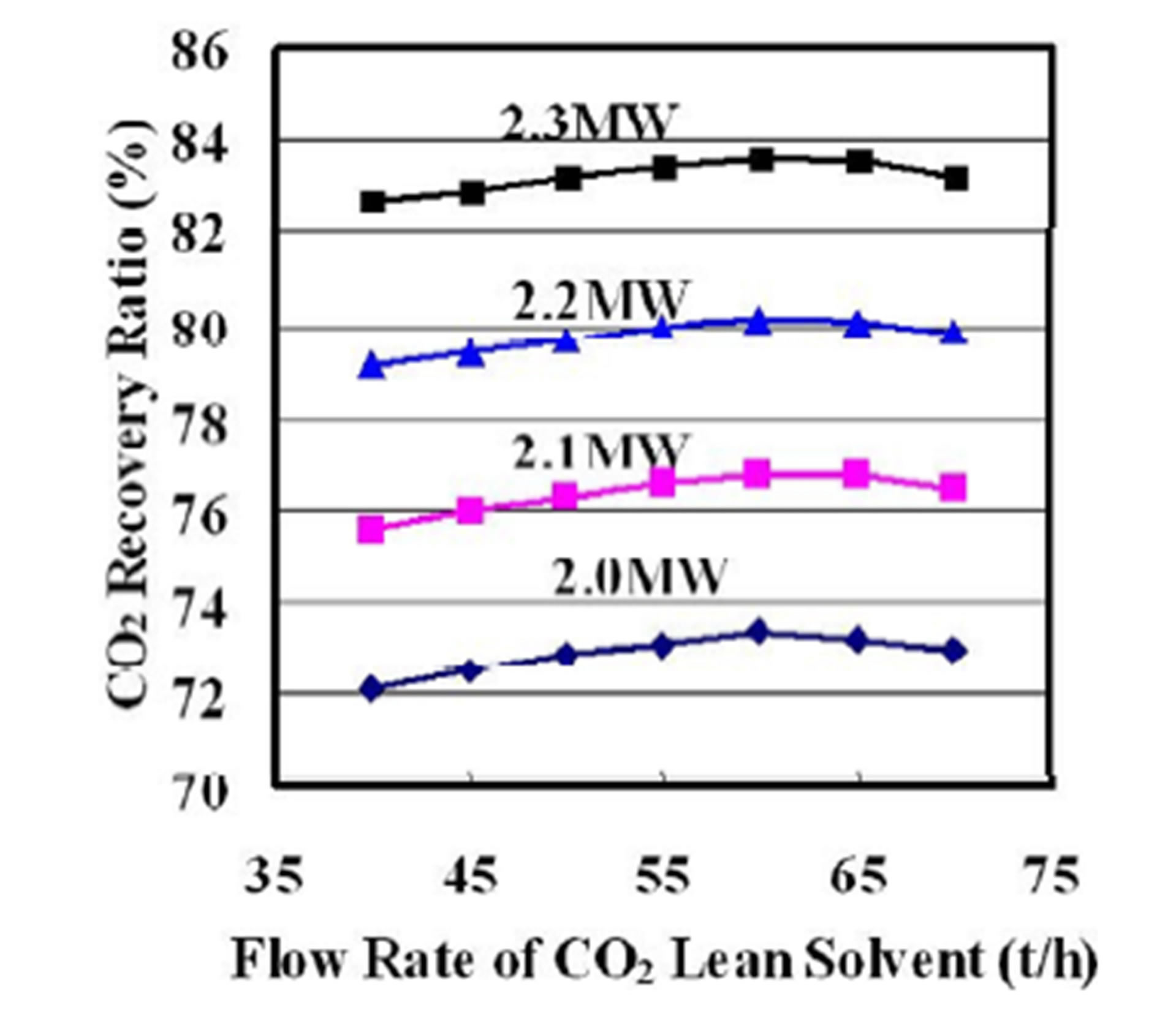
Figure 3. CO2 recovery ratio as functions of flow rate of CO2 lean solvent and reboiler duty.
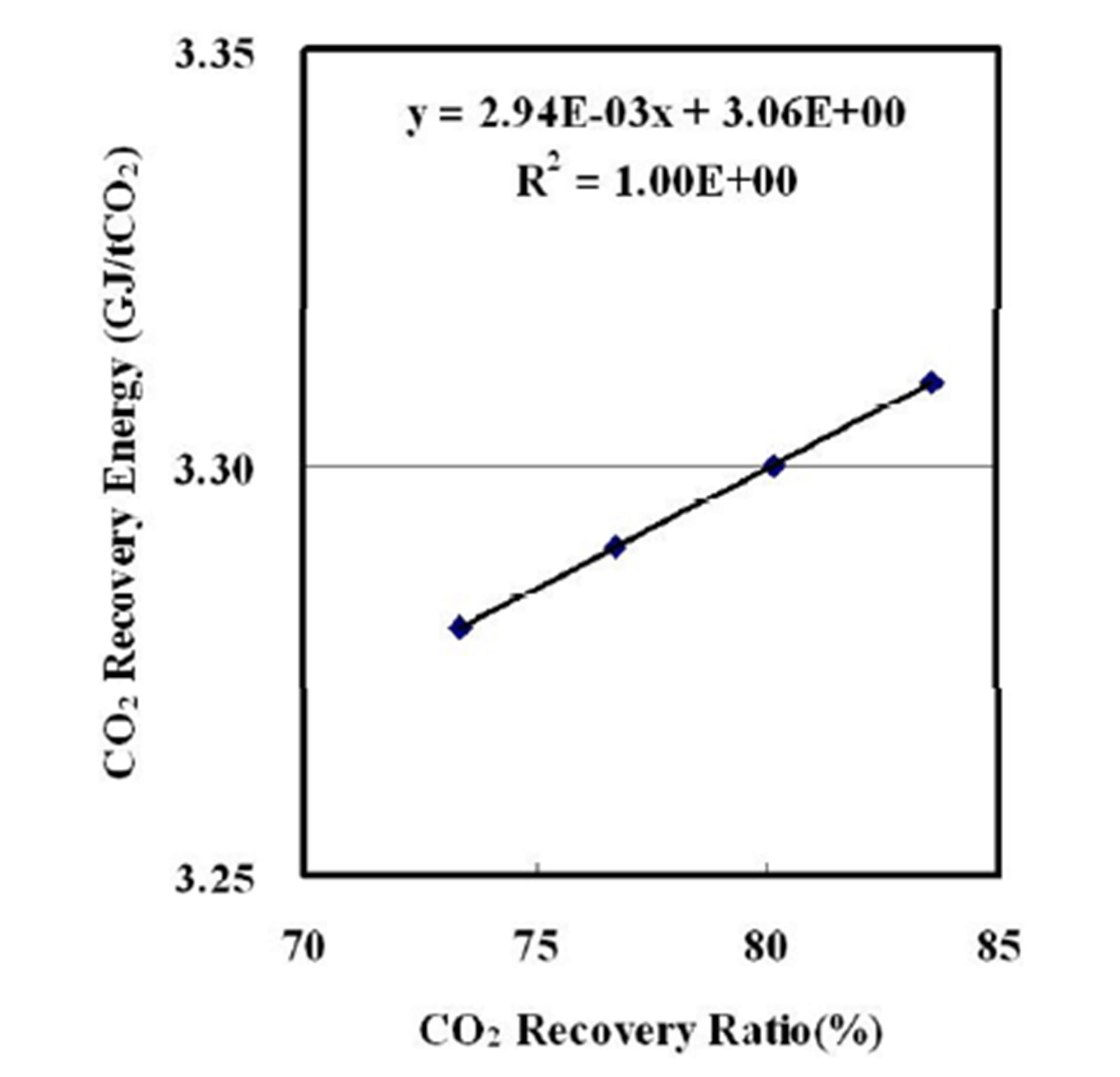
Figure 4. CO2 recovery energy a function of CO2 recovery ratio.
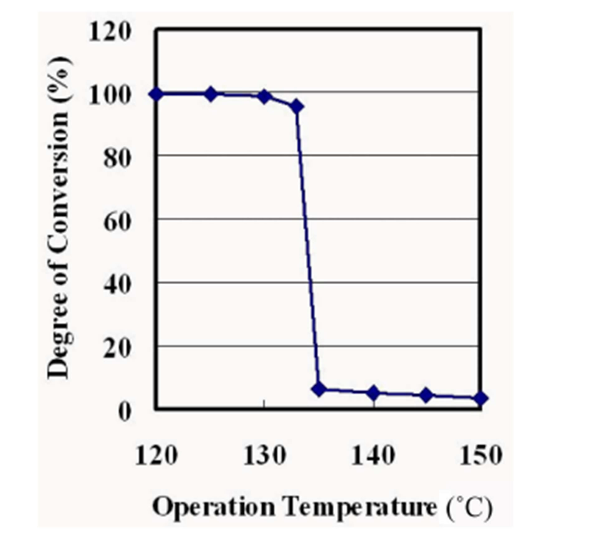
Figure 5. Degree of conversion as a function of operation temperature at 101.3 kPa.
4. Conclusion
The ethylene carbonate synthesis using the carbon dioxide recovered from the gas engine flue gas can supply 76% of the energy requirement for CO2 capture and utilize more than 90% of the captured CO2. The thermal integration of the sodium glycinate absorption and the
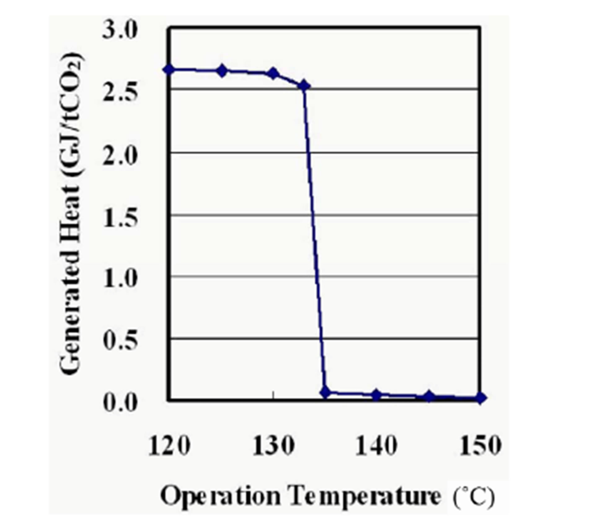
Figure 6. Generated heat as a function of operation temperature at 101.3 kPa.
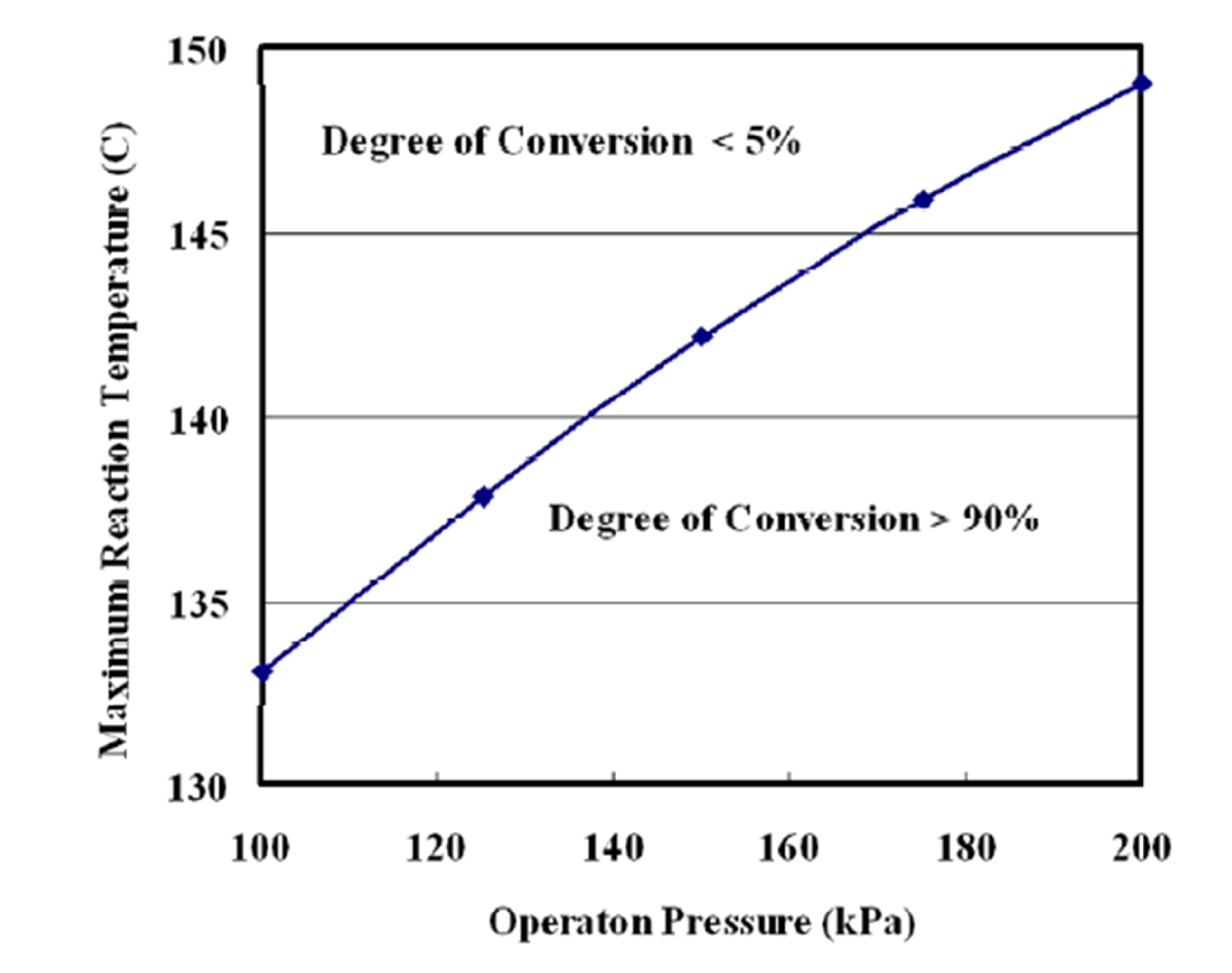
Figure 7. Maximum reaction temperature as a function of operation pressure.
ethylene carbonate synthesis reduces the energy requirement for CO2 capture from 3.3 GJ/tCO2 to 0.8 GJ/tCO2. The energy requirement for the CO2 capture can be supplied by 0.78 MPa saturation steam from the gas engine without its electric power reduction.
REFERENCES
- T. Ogawa, Y. Ohashi, S. Yamanaka and K. Miyaike, “Development of Carbon Dioxide Removal System from the Flue Gas of Coal Fired Power Plant,” Energy Procedia, Vol. 1, No. 1, 2009, pp. 721-724. http://dx.doi.org/10.1016/j.egypro.2009.01.095
- International Energy Agency, “Carbon Capture and Storage.” http://www.iea.org/topics/ccs/
- T. Hallerman, “GE Pushes Dual Plant Fertilization—CO2 Utilization Technology,” GHG News, 2012. http://ghgnews.com/index.cfm/ge-pushes-dual-plant-fertilization-co2-utilization-technology/
- M. North, P. Villuendas and C. Young, “A Gas-Phase Reactor for Ethylene Carbonate Synthesis from Waste Carbon Dioxide,” Chemistry A European Journal, Vol. 15, No. 43, 2009, pp. 11454-11457. http://dx.doi.org/10.1002/chem.200902436
- R. H. Weiland and N. A. Hatcher, “Post-Combustion CO2 Capture with Amino-Acid Salts,” SOGAT 2011—7th International Sour Oil & Gas Advanced Technology, Abu Dhabi, 2011. http://www.ogtrt.com/files/publications/Manuscript_CO2_Capture_with_Amino_Acid_Salts.pdf
- Nihhon Kougyou Syuppan Kuriin Enerugii Hensyuubu, “Tennen Gasu Kohzyenereeshon Kiki Deeta,” Nihhon Kougyou Syuppan, 2012.
- Tokyo Gas, “City Gas 13A—Heating Value, Composition,” (in Japanese). http://home.tokyo-gas.co.jp/userguide/netsuryou.html
- “Sea-Level Composition of Air.” http://www.physlink.com/reference/aircomposition.cfm
- Wartsila, “Wartsila 50SG Engine Technology.” http://www.wartsila.com/file/Wartsila/1278515598410a1267106724867-50SG-Engine-Technology-2012.pdf
- H. Hondo, Y. Uchiyama and Y. Morizumi, “Evaluation of Power Generation Technologies based on Life Cycle CO2 Emissions—Re-Estimation Using the Latest Data and Effects of the Difference of Conditions),” CRIEPI Research Report, 2000. http://criepi.denken.or.jp/jp/kenkikaku/report/detail/Y99009. html