Energy and Power Engineering
Vol. 5 No. 1 (2013) , Article ID: 26374 , 7 pages DOI:10.4236/epe.2013.51001
Investigation and Mitigation of Transformer Inrush Current during Black Start of an Independent Power Producer Plant
1Department of Electrical Engineering, University of Nebraska-Lincoln, Lincoln, USA
2Electric Power Division, Caterpillar, Inc., Peoria, USA
Email: skahrobaee@huskers.unl.edu, Algrain_Marcelo_C@cat.com, sasgarpoor1@unl.edu
Received October 30, 2012; revised December 5, 2012; accepted December 16, 2012
Keywords: Black Start; Distributed Generation; Inrush Current Mitigation; Independent Power Producer; Transformer Energizing
ABSTRACT
The energizing of large power transformers has long been considered a critical event in the operation of an electric power system. When a transformer is energized by the utility, a typical inrush current could be as high as ten times its rated current. This could cause many problems from mechanical stress on transformer windings to harmonics injection, and system protection malfunction. There have been numerous researches focusing on calculation and mitigation of the transformer inrush current. With the development of smart grid, distributed generation from independent power producers (IPPs) is growing rapidly. This paper investigates the inrush current due to black start of an IPP system with several parallel transformers, through a simulation model in DIgSILENT Power Factory software. The study demonstrates that a single genset is capable of energizing a group of transformers since the overall inrush current is slightly above the inrush of the transformer directly connected to the generator. In addition, a simple method is proposed to mitigate the inrush current of the transformers using an auxiliary transformer.
1. Introduction
In an event when the circuit breaker is closed between a transformer and a power source, a transient current (which could be as high as ten times the transformer rated current) follows for a short period before reaching a steady state. This transient current, known as magnetizing inrush current of a transformer, is caused by the transformer’s saturated core.
The excitation characteristic of the transformer core is expressed by a nonlinear relationship between the flux and magnetizing current. In the steady state, transformers are designed to operate below the knee point of their saturation curve. However, when transformers are energized, flux can rise to a high value in the saturation region such that the magnetizing current increases drastically.
Transformer inrush current has long been considered a critical event in the operation of electric power systems [1]. Due to its high magnitude, inrush current may cause mal-trip of protection relays. In addition, it contains significant dc and harmonic components which can affect the sensitive protection functions by artificially changing actual user settings during transformer energization [2,3]. Moreover, inrush current introduces power quality issues [4,5], and imposes mechanical stress on the windings of transformer [6].
Many researchers have worked on calculation and mitigation of transformer inrush currents [7-21]. Authors in [7], proposed an analytical formula to estimate the maximum inrush current. Some others have used a simulated model to study the behavior of the inrush current [8]. In fact, there are various factors affecting the magnitude and duration of the inrush current [3,5]:
• The value of the residual flux in the transformer core;
• The nonlinear magnetizing characteristics of the transformer core;
• The phase of the supplying source voltage at the instant of energizing transformer;
• The impedance and short circuit power of the supplying source.
In fact, the techniques for inrush current mitigation are generally developed based on these factors. While the first two factors are internal and depend on the transformer design and the core material, the other factors are related to the supplying grid characteristics. The solutions based on changing the design of the transformer such as changing the core material or adding an auxiliary winding on the core [9], may be costly and not suitable for all the operation conditions [10]. Using series compensators as inrush current reduction methods, described in [10,11], is complex and expensive to implement. A number of other techniques have been proposed to reduce the core flux prior to circuit energization [12-15]. This approach appears to be simple, based on waveform measurements at the transformer connection point, but inrush currents may not be reduced when the transformer is energized without any history [14]. A more complex method was proposed by [15] which used a low frequency voltage source as transformer demagnetizer. Recently, several studies have been conducted to mitigate inrush currents based on controlling the switching instant of the breaker. It has been shown that the inrush current can be reduced by using a series resistance at the neutral point of a transformer and sequential switching of each phase of the transformer at the time of energization [16- 18]. In a case that a delta-star transformer is energized from the delta side, series resistance can only be inserted in the line and not in the delta winding of the transformer. Authors in [19] argue that controlled switching in this case can only limit the inrush current in one line. There are also some practical issues in using controlled energization such as deviation in actual breaker switching times, and difficulties in correct measurement of residual flux [20].
As the power grid is moving toward accommodating more distributed generation, the need to study the effect of inrush current during the start of these units is evident. An installation of distributed generation from an IPP may be comprised of several parallel generation units. Since each generator is connected through a transformer, simultaneous switching of all the units can induce a significant inrush current in the system. In this paper, a distributed generation system is modeled and the possibility of energizing a set of parallel transformers through a single generator is investigated. Next, a new approach using an auxiliary transformer is proposed to further mitigate the inrush current of a main transformer in a distributed generation facility. In order to evaluate the proposed method, the worst case scenario is simulated where the power of the magnetizing source is not limited. The results demonstrate the effectiveness of the proposed method in inrush current mitigation.
2. Problem Statement and the Approach
In the event in which a transformer is energized by the utility line, a typical inrush current would be about 10 times its rated current. If energized by a less capable source, such as a generator set, the current inrush would be somewhat less than when energized by a utility line, but still very large because of the large short circuit current capability of a synchronous generator. In either case, the severe power transient induced by switching on transformers can be very disruptive to the electrical system, particularly when it is being powered up.
For example, consider the case of black starting of a distributed generation system of an IPP installation. In this case, a set of up to 16 transformers and generators is being energized. This part of the IPP system is schematically shown in Figure 1. If the utility line is live, switching on transformers T1 through T16 would not induce a significant inrush current if the transformers were to be energized in a stagger mode allowing sufficient time for the inrush current on each transfer to decay sufficiently (typically 2 to 3 seconds) before switching on the next transformer. However, typically due to cost constraints, in most cases the connection between the transformer and the utility line would be made using a fuse protected switch which would not allow for staggering transformer switch-on, and therefore, all transformers would be energized simultaneously. Energizing multiple transformers at once would then induce a much stronger inrush current onto the utility line, but with a reasonable stiff power source it would be well within the utility source capabilities.
On the other hand, if a stiff power source was not available, there is a degree of uncertainty as to how many generator sets would be able to handle the large inrush current from all transformers switched on at once. In case that multiple generators were needed for energization, their output would need to be synchronized prior to connection to the main electrical bus. Some IPP plants have the capability of using dead-field paralleling of multiple generators to energize the electrical bus under a black start condition. The presumption is that by gradually raising the generator excitation voltage as multiple units come up to speed, the generators would boot-strap themselves into synchronization and energize all transformers simultaneously. In theory, a large inrush would be avoided because generator voltage would be ramped up from null to nominal over a couple of seconds. In practice, however, dead-field paralleling can be rough on equipment because of the potentially high circulating stator currents that occur when paralleling unloaded generators, and in the IPP case the situation is aggravated because the generators are not unloaded as they would be energizing multiple transformers. In this scenario, the generators would be further stressed by the use of dead-field paralleling and the risk of failing to synchronize would be higher.
To avoid these issues, this paper investigates the possibility of handling the inrush from multiple transformers, with a configuration similar to Figure 1, using a single generator as an energizing source. In addition, an auxiliary transformer is used to further mitigate the inrush current when a large capacity source is energizing the main transformer.
3. Modeling
The model of the simulated system (Figure 1) is built using DIgSILENT software. The system comprises of 16 generator-transformers connected to a single bus. This bus is also connected to an external grid that represents the equivalent model of the rest of the network. However, during a black start the external grid is disconnected; and it will not contribute to the inrush current of the transformers. All transformers are identical and so are the generators. The transformers are 13.2/0.48 kV, with a Delta/Wye connection, and their specifications are provided in Table 1. Nonlinear magnetizing characteristics of the transformer are modeled using two different magnetizing reactances before and after the saturation point. The diesel generators have a power rating of 2.5 MW, and their other electrical characteristics are listed in Table 2.
In addition to the restrictions mentioned in the introduction section, the inrush current of the transformer is also limited by the instantaneous current capability of the generator as shown in Figure 2.
The output current of the generator lies below this curve at different time cycles as verified during the simulation.
Representative models for AVR, prime mover unitand governor are also included in the simulated model. These models enable the generator to stabilize after being subjected to a high inrush current, and reach to the steady state condition after the transient time is passed.
4. Inrush Current Study
This study examines the inrush current during energizing different number of transformers connected to a busbar while energized by a single generator (G1 in Figure 1).
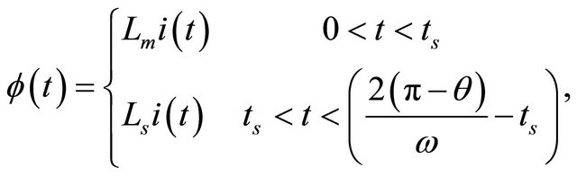
Figure 3 shows a flux-current characteristic with two slope representation of a transformer’s magnetic flux before and after saturation point denoted by Lm and Ls, respectively. With a sinusoidal phase voltage of v(t) = Vmsin(ωt + θ) applied to the transformer, magnetic flux can be calculated by integration as:
 (1)
(1)
where Vm, ω, and θ are the magnitude, angular frequency, and the initial phase angle of the applied voltage, respectively. ϕ0 is the residual magnetic flux of the transformer core. The transformer saturation occurs when ϕ(t) = ϕs, where ϕs is the knee magnetic flux.
Therefore, the saturation time, ts, can be calculated as:
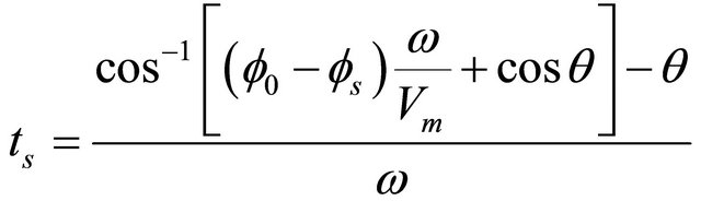 (2)
(2)
Considering that:
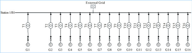
Figure 1. Schematic diagram of IPP generation system with 16 gensets.
Table 1. Main parameters of transformers.

Table 2. Main parameters of diesel generators.

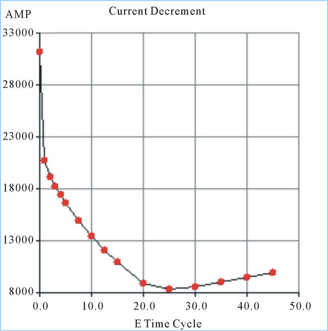
Figure 2. Current decrement data of the modeled generator.

Figure 3. Two slope modeling of flux-current characteristics of a transformer.
 (3)
(3)
Equation (4) provides an analytical estimation for the maximum inrush current [21].
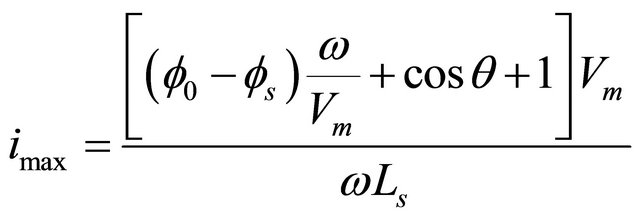 (4)
(4)
This equation determines how the residual flux, switching angle, and the saturation inductance affect the inrush current of a transformer.
Figure 4 shows the three phase inrush current from energizing of one transformer (T1 in Figure 1). The switch closes at 0.5 second and the initial peak current is as high as 16 kA in this study. The current also includes some DC values which decay over time. The effective value of the inrush current is about 11 kA.
In a case where all 16 transformers are energized by a single generator, the inrush currents are shown in Figure 5. The transformers are magnetized at 0.5 and the initial peak current is about 20 kA in this study.
It is observed that although the number of transformers has been multiplied by a factor of 16, the inrush currents only increase by about 27%. This is mainly due to both the current decrement curve of the generator and the configuration of the simulated network. Unlike grid side energization where transformers would be connected in parallel and the inrush of each transformer adds up in a cumulative manner, here, transformer T1 is connected in series with G1 and therefore, the total magnetizing current is dominated by the inrush of T1. In other words, transformer T1 becomes the bottleneck of the overall current inrush and the total current inrush is no longer cumulative.
A summary of results for energizing different number of transformers is shown in Table 3. From the table, it is observed that the total inrush currents for four, eight, and sixteen transformers are 23%, 26%, and 27% larger than for a single transformer, respectively. If we choose to switch transformers at voltage zero-crossing instant, the calculated inrush currents will be approximately 10% higher.
Hence, the results in Table 3 confirm that a single generator set would be capable of energizing comparably rated transformers provided that the first transformer is connected in series to the generator and the remaining transformers are connected in parallel to the first transformer. Unlike the inrush current, the steady state magnetizing current of all transformers add up one of top of the other. Given that the no load steady state transformer current is typically less than 3% of the rated current, a single generator would be able to power over 30 transformers at no load condition covering transformer losses.
5. Inrush Current Mitigation
Although transformer inrush currents of an IPP generation system studied in the previous section do not add up linearly with higher number of gensets, they still could be considerably high especially with a high capacity generator. A new approach is presented in this paper to mitigate the magnitude of a transformer inrush current using a smaller auxiliary transformer. The principle behind this approach is that a smaller transformer inherently has a lower inrush current and its impedance can reduce the inrush current of the main transformer when they are connected in series during the enegization time. In the proposed method, the auxiliary transformer is temporarily switched-on into the circuit to energize a larger main transformer, and to limit the magnitude of the overall inrush current. Once the power-up transient is over, the auxiliary transformer is bypassed and only the main transformer remains connected to the circuit.
In order to consider the worst case scenario in the study, the capacity of the magnetizing generator was increased so that it does not restrict the inrush current required by the transformer. Figure 6 depicts the inrush current of a transformer without any limiter in this case. The inrush current is approximately 37 kA which is about 10 times higher than the transformer’s rated current.
The configuration for energization of the 3 MVA transformer using a 300 KVA auxiliary transformer is shown in Figure 7.
In Figure 7, the secondary sides of the two transformers are connected during energization. Transformer T1 is not initially connected to the generator, and it is energized through its 13.2 kV connection. Once the main transformer T1 is fully energized, the auxiliary transformer Ta is switched-off and transformer T1 is switched-on to the generator simultaneously.
The characteristics of the auxiliary transformer are presented in Table 4.
The main and auxiliary transformers may be energized separately or at the same time. Figure 8 shows the inrush currents drawn from G1 where Ta is connected first and T1 is energized 0.5 seconds later.
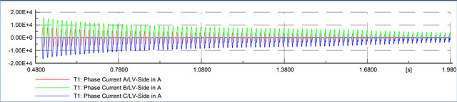
Figure 4. Three phase inrush current of transformer T1 energized by G1.
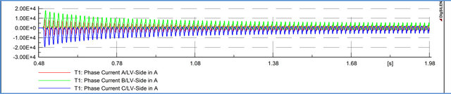
Figure 5. Three phase inrush current of all 16 transformers energized by G1.
Table 3. Magnitudes of inrush and steady state magnetizing currents for different number of transformers.
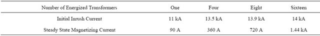

Figure 6. Three phase inrush current of a transformer without limit.
The inrush current is about 5 kA for the main transformer and 3.8 kA for the auxiliary transformer. By comparing this case with the previous one without auxiliary transformer (Figure 6), it is observed that the inrush current has reduced by 86%. In addition, the duration of the inrush current per energization of transformer has been considerably decreased.
If we choose to energize both the auxiliary and main transformers simultaneously, the inrush currents are as shown in Figure 9.
The inrush current in this case is 6 kA which is 1 kA higher than the case with sequential energization, but still it is considerably less than the inrush current without using this method. In short, the inrush current mitigation process on the single line diagram of Figure 7 can be explained as follows:
1) Connect the generator side switch of Ta, while both Ta and T1 are connected to bus B1. This configuration will energize both transformers.
2) Keep the connection until the inrush current decays with time.
3) Disconnect Ta and connect the primary side of T1 to G1. This is possible because the voltages at both G1 terminal and T1 have the same phase angle.
6. Conclusion
This study models the black starting of a distributed generation system of an IPP installation. In the first part of this paper, it is demonstrated that the total inrush current associated with energizing a large group of transformers,
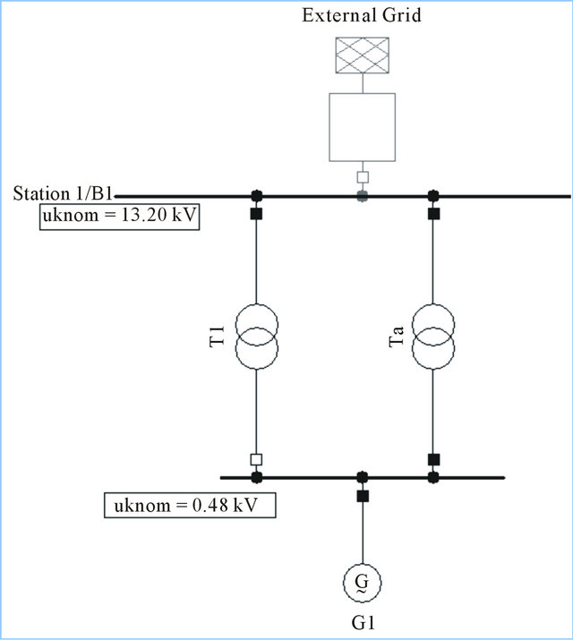
Figure 7. Single line diagram of the main and auxiliary transformers connections.
Table 4. Main parameters of the auxiliary transformer.

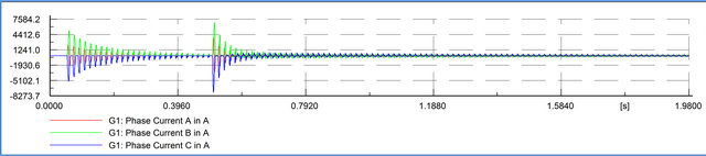
Figure 8. Three phase inrush current from a sequential energization of the auxiliary and main transformers.
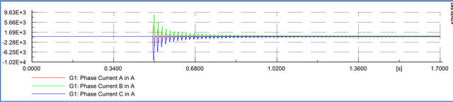
Figure 9. Three phase inrush current from a simultaneous energization of the auxiliary and main transformers.
when fed by a single generator/transformer combination, is only increased by less than 30% over the inrush of a single transformer. Therefore, it is not necessary to parallel multiple gensets to energize an electrical bus under black start conditions, and the use of deadfield paralleling in such cases would be unnecessary. In the second part of this paper, a new approach is proposed to further mitigate main transformer’s inrush currents in a distributed generation system using a smaller auxiliary transformer. This proposed approach is simple to implement and does not require any measurement-based controls. The results indicate that using this method, the inrush current can be reduced by more than 80%.
REFERENCES
- L. F. Blume, G. Camilli, S. B. Farnham and H. A. Peterson, “Transformer Magnetizing Inrush Currents and Influence on System Operation,” AIEE Transactions, Vol. 63, No. 6, 1944, pp. 366-375.
- B. Kasztenny, “Impact of Transformer Inrush Currents on Sensitive Protection Functions,” IEEE Transmission and Distribution Conference and Exhibition, 21-24 May 2006, pp. 820-823.
- L. C. Wu, C. W. Liu, S. E. Chien and C. S. Chen, “The Effect of Inrush Current on Transformer Protection,” 38th North American Power Symposium, Taipei, 17-19 September 2006, pp. 449-456.
- M. Nagpal, T. Martinich, A. Moshref, K. Morison and P. Kundur, “Assessing and Limiting Impact of Transformer Inrush Current on Power Quality,” IEEE Transactions on Power Delivery, Vol. 21, No. 2, 2006, pp. 890-896. doi:10.1109/TPWRD.2005.858782
- R. A. Turner and K. S. Smith, “Transformer Inrush Current,” IEEE Industry Applications Magazine, Vol. 16, No. 5, 2010, pp. 14-19. doi:10.1109/MIAS.2010.937440
- M. Steurer and K. Fröhlich, “The Impact of Inrush Currents on the Mechanical Stress of High Voltage Power Transformer Coils,” IEEE Transactions on Power Delivery, Vol. 17, No. 1, 2002, pp. 155-160. doi:10.1109/61.974203
- Y. Wang, S. G. Abdulsalam and W. Xu, “Analytical Formula to Estimate the Maximum Inrush Current,” IEEE Transactions on Power Delivery, Vol. 23, No. 2, 2008, pp. 1266-1268. doi:10.1109/61.974203
- J. G. Slootweg and R. A. C. de Groot, “Calculation of Transformer Inrush Currents Occurring during the Energizing of the Public Grid after a Major Black Out,” IEEE Conferences of Russia Power Technology, Arnhem, 27-30 June 2005, pp. 1-7.
- V. Molcrette, J. L. Kotny, J. P. Swan and J. F. Brundny, “Reduction of Inrush Current in Single-Phase Transformer Using Virtual Air Gap Technique,” IEEE Transactions on Magnetics, Vol. 34, No. 4, 1998, pp. 1192-1194. doi:10.1109/20.706479
- J. L. Shyu, “A Novel Control Strategy to Reduce Transformer Inrush Currents by Series Compensator,” International Conference on Power Electronics and Drive Systems, Vol. 2, 2005, pp. 1283-1288. doi:10.1109/PEDS.2005.1619885
- P. Arboleya, D. Diaz, C. Gonzalez-Moran, J. Coto and J. Gomez-Aleixandre, “An Inrush Current Limiter as a Solution of Injection Transformer Oversizing in Dynamic Voltage Restores,” International Conference on Electrical Machines and Systems, Gijon, 15-18 November 2009, pp. 1-6. doi:10.1109/ICEMS.2009.5382735
- D. P. Balachandran, R. S. Kumar and V. P. Shimnamol, “A New Technique for Mitigation of Transformer Inrush Current,” 19th International Conference on Electricity Distribution, Vienna, May 2007.
- D. P. Balachandran, R. S. Kumar and V. P. Shimnamol, “Transformer Inrush Current Reduction by Power Frequency Low Voltage Signal Injection to the Tertiary Winding,” IEEE Lausanne on Power Technology, Trivandrum, 1-5 July 2007, pp. 1953-1958. doi:10.1109/PCT.2007.4538616
- L. C. Wu and C. W. Liu, “The Inrush Current Eliminator of Transformer,” Proceedings of the 2011 2nd International Congress on CACS, Vol. 144, 2012, pp. 411-419.
- B. Kovan, F. de Leon, D. Czarkowski, Z. Zabar and L. Birenbaum, “Mitigation of Inrush Currents in Network Transformers by Reducing the Residual Flux with an Ultra-Low-Frequency Power Source,” IEEE Transactions on Power Delivery, Vol. 26, No. 3, 2011, pp. 1563-1570. doi:10.1109/TPWRD.2010.2102778
- W. Xu, S. G. Abdulsalam, Y. Cui and X. Liu, “A Sequential Phase Energization Technique for Transformer Inrush Current Reduction—Part II: Theoretical Analysis and Design Guide,” IEEE Transactions on Power Delivery, Vol. 20, No. 2, 2005, pp. 950-957. doi:10.1109/TPWRD.2004.843465
- F. Ali Asghar and K. P. Basu, “Reduction of Three-Phase Transformer Magnetizing Inrush Current by Use of Point on Wave Switching,” Student Conference on Research and Development, Cyberjaya, 16-18 November 2009, pp. 368-370.
- K. P. Basu and S. Morris, “Reduction of Magnetizing Inrush Current in Traction Transformer,” Third International Conference on Electric Utility Deregulation and Restructuring and Power Technologies, Cyberjaya, 6-9 April 2008, pp. 2302-2305. doi:10.1109/DRPT.2008.4523795
- K. P. Basu, A. Asghar and S. Morris, “Effect of Sequential Phase Energization on the Inrush Current of a Delta Connected Transformer,” International Conference on Power Electronics, Drives and Energy Systems, Cyberjaya, 12-15 December 2006, pp. 1-4.
- J. H. Brunke and K. J. Frohlich, “Elimination of Transformer Inrush Currents by Controlled Switching Part II: Application and Performance Considerations,” IEEE Transactions on Power Delivery, Vol. 16, No. 2, 2001, pp. 281- 285. doi:10.1109/61.915496
- Y. Wang, S. G. Abdulsalam and W. Xu, “Analytical Formula to Estimate the Maximum Inrush Current,” IEEE Transactions on Power Delivery, Vol. 23, No. 2, 2008, pp. 1266-1268. doi:10.1109/TPWRD.2008.919153