Communications and Network
Vol.1 No.2(2009), Article ID:913,6 pages DOI:10.4236/cn.2009.12009
A Novel Topology for the Zonal Network with Wireless Coverage
1Research Center for Next-Generation Internet Tech & Apps, Fujian University of Technology, Fuzhou, China
2College of Business Administration, Texas Tech University, Lubbock, TX, USA
E-mail: fuminzou@ngi.fj.cn, zhangxi.lin@ttu.edu
Received August 5, 2009; accepted September 4, 2009
Keywords: Banyan-Tree Topology, Zonal Network, Wireless Coverage, Transportation
Abstract
In this paper, we propose a banyan-tree topology for the wireless coverage along the road or railway, which is characterized as a zonal network. Theoretical analysis and numerical studies show that the proposed banyan-tree topology is appropriate for the zonal network with the Wireless Mesh Network (WMN) technology, which is feasible to deploy and has the enhanced robust, improved bandwidth with this topology.
1. Introduction
While the population of Internet users in China has reached 338 millions by June 2009 [1], 26.8 billion passengers on road [2] and 1.46 billion on railway [3] spend billions of unproductive hours during their traveling, showing that it is not only the demand to promote the transportation service quality, but also a great potential market for the Internet services on the fleeting car [4]. As well as the Car-Ground Internetworking (CGI), the Zonal Wireless Coverage (ZWC) is another essential infrastructure for the onboard Internet applications.
For the ZWC, WiFi is an appropriate technology that is technically and economically feasible, and has attracted substantial attention in the wireless and transportation communities [5–8]. However, deploying hundreds even thousands of APs along the road or railway is a main challenge to this promising technology because of the limited coverage. So far, several topologies have been put into trial implementation for the ZWC with WiFi. Among them, the star topology was found almost infeasible since too many cables are require, and the bus topology is also infeasible because the multi-hop Wireless Mesh Network (WMN) is too weak [9,10].
This paper proposes a novel topology for the deployment of WiFi in the ZWC context. It is claimed that the WMN is feasible to implement the ZWC with fewer cables to deploy and its robust can be promoted to some extent by splitting the multi-hop WMN to multiple sectors [5]. However, if a mesh node failed, its subsequent nodes in the same chain will become invalid too. As an improvement of the splitting scheme, our approach lets the packets to be forwarded via a most reliable path in the zonal network, in which all the nodes are connected one by one with wireless link, while a number of portals are deployed to the wired network. To avoid the circle and get the most reliable path, we designed a Dynamical Minimal Spanning Tree (DMST) algorithm, which will update the forwarding path periodically according to the dynamical changing fault probability. Hence, the packets can be forwarded via another path to its destination automatically once a mesh node failure.
To overcome the bandwidth problem which is reported in references [11,12], i.e., the bandwidth dramatically decreased as 1/n even  in multi-hop WMN, the multi-interface mesh node structure is introduced and it is found that the banyan-tree topology has an improved bandwidth in ZWC.
The outline of this paper is as follows. In Section 2, we present the banyan-tree topology. The algorithm DMST is designed in Section 3, and the network robust, bandwidth and etc are analyzed in Sections 4 and 5. Section 6 presents outcomes from the numeric study, and this paper is concluded by Section 7.
2. Banyan-Tree Topology
Definition 1: Let G=(V, E) be a connected graph with |V| = n+1 nodes, if
1) G has a Hamiltonian cycle ;
;
2) G at least has a node  connecting
  except
  and
and .
.
Then we call graph G as a banyan-tree topology.
Where  is called the root and its neighbors are called prop-nodes. Let
  be the order set of prop-nodes, if
  then it is a star topology, else if
  then it is a bus topology. Figure 1 is an example of banyan-tree topology.
Apparently, the banyan-tree topology contains a number of circles which should be avoided in data communication that requires the packets forwarded along a certain minimal spanning tree. Hence, let us draw a weighted graph G=(V,E,W) by assigning a cost to each edge, where W is the set of weights. Then the best forward path can be computed by a minimal spanning tree algorithm.
Let the danger coefficient of each edge be its cost, and give the related definitions as follows.
Definition 2: Let , if
, if  is a maximal path extended from
 , where
 , then
  is called a multi-hop chain.
Obviously, for every node 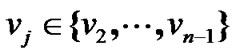 it has
 , where
 .
.
Definition 3: for every node , we denote
 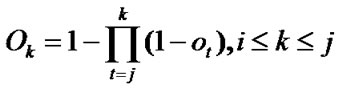 as its partially invalidated probability (PIP), where
  is the fault probability of each node in the chain.
Let us see the example of Figure 1. If  =1‰ for any
  then
then  2.997‰ according to the Definition 3. Hence this definition is reasonable because if any node of
  failures, the packets from
  cannot reach
  via this path.
Since a node  is associated to two multi-hop chains, it has two PIPs, say
 . Then its completely invalidated probability (CIP) in the banyan-tree topology is
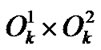 . But for the minimal spanning tree every node will belong to a certain multi-hop chain, hence we define the danger coefficient as follows.
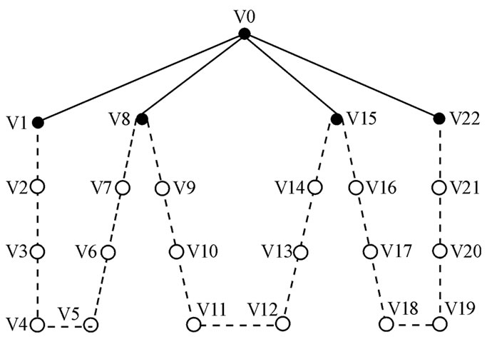
Figure 1. Example of banyan-tree topology.
Definition 4: Denote the pair of PIPs of  in its left and right multi-hop chain as
 , and denote its danger coefficient as
 .
.
To simplify, we assume that danger coefficients of both  and wired network are 0, and the danger coefficient of edge <
 ,
, > is equal to
 . These imply that our discussion is based on the condition when
  and the wired network are running normally, and the state of the wireless link is determined by the mesh node. With these assumptions, let the fault probability of each node be 1‰ except
 , then the spanning tree of Figure 1 with the minimal invalid risk can be shown in Figure 2.
3. Dynamical Minimal Spanning TreeAlgorithm
When a mesh node failures, packets should be automatically forwarded via the alternative path to its destination. Furthermore, when a node’s fault probability is varying in accordance with time, the ZWC should be able to dynamically find a more reliable path to forward the packets. Assume that the fault probability vector is  except
  at time
 , the algorithm DMST is designed as follow.
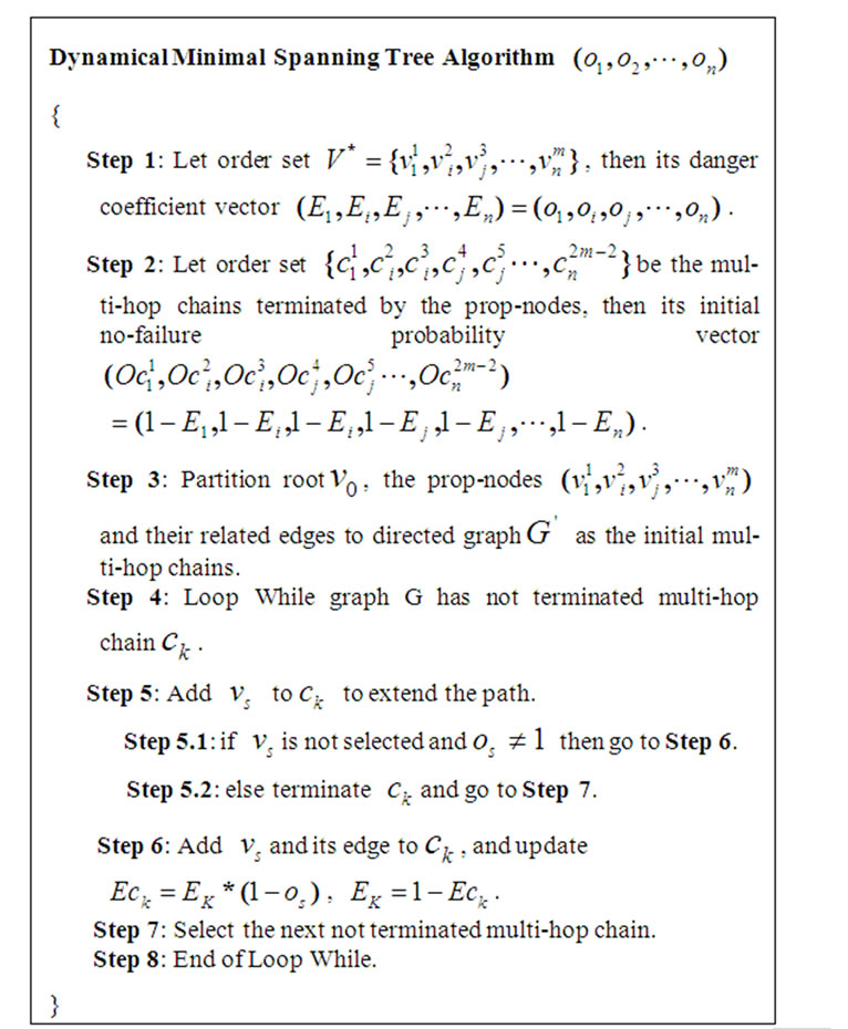
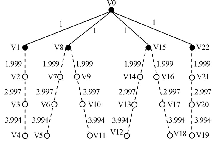
Figure 2. Spanning tree of the banyan-tree topology.
Graph  is the minimal spanning tree according to the time-dependent fault probability.
Proposition 1: The time complexity of Algorithm DMST is O(|V|+|E|).
Proof. Assume that graph G is a banyan-tree topology. Then ,
,  belongs to a multi-hop chain
  and
and , according to Definition 3 and 4. Hence the algorithm DMST only need do a breadth-first search (BFS) for graph G to get the spanning tree with minimal invalid risk.
The time complexity of BFS algorithm for graph G is O(|V|+|E|) [13]. Hence, the time complexity of algorithm DMST is O(|V|+|E|). Q. E. D.
4. Network Robust Analysis
Now we analyze the network robust of banyan-tree topology.
Proposition 2: The vertex connectivity of banyan-tree topology .
.
Proof. Assume that graph G is a banyan-tree topology. Then G has a Hamiltonian cycle  according to Definition 1. This means that
 , the number of connected components
 , hence
 . But when two nodes
  and
and  (
( ) failures,
 , hence
 .
.
Therefore, the vertex connectivity of banyan-tree topology . Q. E. D.
The network robust can be evaluated by the vertex connectivity for the traditional network. But for the ZWC with multi-hop WMN technology, the impact level of fault nodes must be assessed because a fault node always undertakes the task of packet relay for other nodes.
Definition 5: Denote the banyan-tree topology G=(V,E) and the order set of fault nodes ,
, . Assume that
  is the largest connected components which are connected with
  when the fault nodes are deleted, i.e.,
  , then
 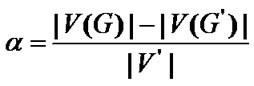 is the impact factor and
  is the number of invalidated nodes.
The non-fault nodes in the isolated components which are disconnected from  will become invalid, when the graph G becoming a disconnected graph affected by fault nodes. Hence defined as the ratio of the invalided nodes to fault nodes, the impact factor is appropriate to evaluate the network robust.
Proposition 3: Let the graph G=(V,E) be a banyan-tree topology, where , the order set of fault nodes
 , and the order set of prop-nodes
 . If
. If

 (1)
(1)
then the impact factor .
.
Where  are the nodes of the shortest path which connects prop-node
  to
to and except
 .
.
Proof. According to (1), given a banyan-tree topology G=(V,E), for any circle  of G,
of G,  either has only one node or several adjacent nodes failure . Hence the nodes in
  are still connected when the fault nodes are deleted. In this way,
 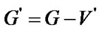 is a connected graph for the arbitrariness of
 .
.
Therefore we have 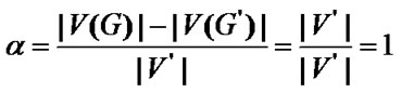 according to Definition 5. Q. E. D.
Let graph G=(V,E) be a banyan-tree topology, the Factor a Algorithm is designed as follows for any order set of fault nodes ,
, .
.
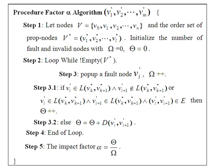
where  is the length of the shortest path
 , which connects fault node
  to
to except
5. Bandwidth and Latency Analysis
Because the node in multi-hop WMN is not only need to provide the access for wireless users, but to undertake the task of packet relay for the left and right neighbors, the bandwidth will be decreased dramatically while the multihop chain increasing. Hence a multi-interface mesh node structure is presented as Figure 3.
The mesh node has 1 wired interface and 3 wireless interfaces, which is in charge of the wireless access, ingress and egress packet relay individually. When it acts as a prop-node, the traffic in the multi-hop chain is converged to the root node  via the wired interface. To forward the packets among these interfaces, the mesh node is designed as a layer 2 device by utilizing a bridge module.
Assume that the access location is  for user X, and the packets are relayed to prop-node
  step by step along the multi-hop chain
  (let
(let  for simply illustration), then the packets will be transmitted and forwarded with n steps, where
 (2)
(2)
5.1. Latency Analysis
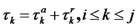
Apparently the packet relay includes two processes as packet transmission between the neighbor nodes and packet forward among the internal interfaces. Let us denote that the transmission latency is  and the forward latency is
 , then the total latency for user X is
 (3)
(3)
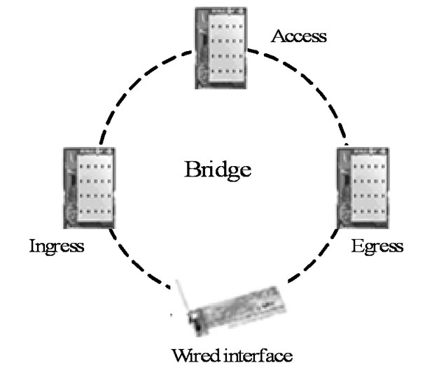
Figure 3. Mutlit-interface mesh node structure.
Because the mesh node should be in charge of the wireless access, ingress and egress packet forward, its media access control is more complex than the traditional network. Hence a concept of interval is introduced here to characterize the fluency of traffic, i.e., the waiting time for next transmission since user X has sent the current packet. Let us denote that the transmission interval is  and the forward interval is
 , then the total interval for user X is
 (4)
(4)
Assume that the vectors of transmission and forward time of nodes in  are
are  and
and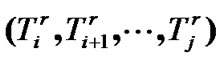 , then the latency of user X to transmit the packets to prop-node
 is
is
 (5)
(5)
because these tasks must be performed in serial.
As the contribution of multi-interface structure, the mesh nodes can perform the wireless access, ingress and egress transmission and packet forward in parallel. Hence the interval of user X to transmit the packets to prop-node  is
is
 (6)
(6)
5.2. Bandwidth Analysis
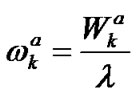
Obviously the bandwidth of user X is restricted by the access link and multi-hop chain. Let us denote that the access, convergence and final bandwidth of user X are
 ,
,  and
and , then it has
 (7)
(7)
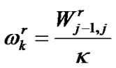
As the outcome of multi-interface mesh node structure, the multi-hop WMN has solved the bandwidth problem [14]. But as the backbone for all the users in the multi-hop chain, the node that is nearer to the prop-node should undertake more packets relay task. Assume that the vectors of access and convergence bandwidth are  and
and 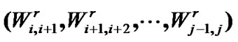 within
 , and the amount of user within
  and
and  is
is  and
and  individually, then it has
 (8)
(8)
 (9)
(9)
with a simplest and affair bandwidth assignment policy applied.
6. Numerical Study
In this section, we make an illustrative implementation proposal for a railway wireless coverage with 300Km distance. Assume that the coverage of each AP is 1Km and its fault probability is 0.1% independently, and it requires that
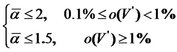 (10)
(10)
where  is the average impact factor and
  is the fault probability of set
 .
.
Obviously, this test bed needs to deploy about 300 APs along the railway. To estimate the number of prop-nodes, we developed a simulation system with c programming language in Linux operation system to implement the factor a algorithm. In this simulation system, we assume that all the nodes are deployed evenly and their fault probabilities are equal and independently. Let the number of APs, i.e. the number of nodes,  =301. When the number of prop-nodes
  and fault nodes
  are (4,6,7,11,16) and (1,2,3) respectively, we obtained the distribution of
  as shown in Figure 4.
Set the fault probability of every node as 0.1% and independently, then it has
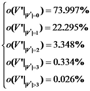 (11)
(11)
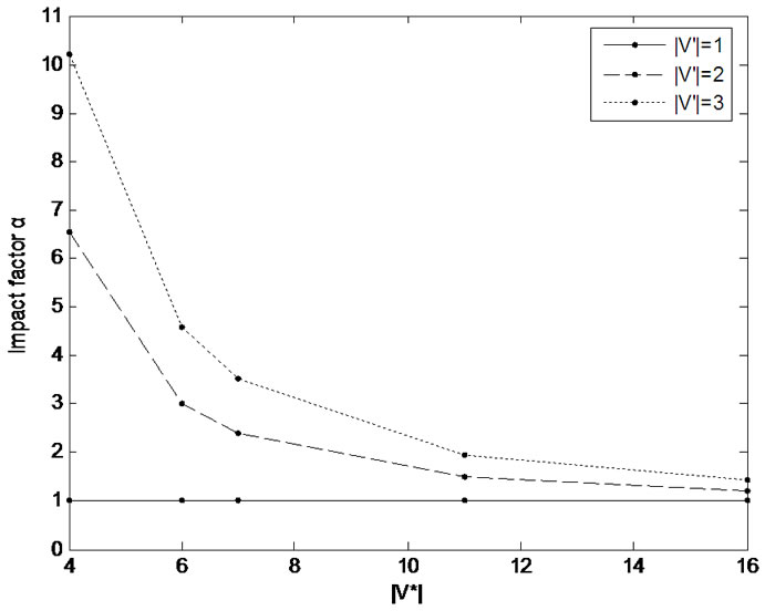
Figure 4. The distribution of average impact factor a.
According to (11), the Equation (10) can be converted to
 (12)
(12)
Based on the distribution of  with simulation, we can set
  to meet with the requirement of (10), i.e., deploy a prop-node every 30Km.
As the most density of train running schedule in China, there has no more than 3 trains in the 30Km sector. As a typically bandwidth of WiFi for access and convergence,  and
and  may be deployed as 20Mbps and 60 Mbps [14], then the bandwidth for each train as
  =20Mbps according to Equations 8,9, which is more than the solutions with satellite and 2G/3G network technologies nowadays.
7. Conclusions and Discussion
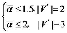
Banyan-tree topology provides an alternative networking scheme for the ZWC with WiFi while the star topology requires too many cables and the bus topology is too weak. Numeric studies show that it only requires deploying 11 prop-nodes to wired network for a railway wireless coverage with 300Km distance, and the average impact factor  when the fault probability
  and
and  when
when . At the same time, it can provide each train with 20Mbps bandwidth, which is more than the current solutions. Future work includes the capacity model for banyan-tree topology based ZWC and a dynamical fault probability detection scheme.
8. Acknowledgments
The work was supported financially by the Fujian Provincial Department of S&T through the project AEED (No. 2008-80) and Wi-Road (No. 2009-27).
9. References
[1] China Internet Network Information Center, the 24th Statistical Report on Internet Development [R], Beijing, China, July 2009.
[2] Ministry of Tranport of the People’s Republic of China, Statistical Communique on the 2008 Road and Waterway Development [R], Beijing, China, April 2009.
[3] Ministry of Railways of the People’s Republic of China, Statistical Communique on the 2008 Railway Development [R], Beijing, China, June 2009.
[4] X. H. Jiang, F. M. Zou, Z. X. Lin, and T. S. Wang, “A Survey on the Internet Application on Passenger Train [J],” Journal of the China Railway Society, Vol. 29, No. 5, pp. 103–110, 2007.
[5] Roamad, “Highway Wi-Fi networks: A RoamAD whitepaper with a case study on the Arizona I-19 highway WiFi corridor [R],” February 2006http://www.kordiasolutions.com/files/RoamAD_Case_Study_Arizona_Highway_Wi-Fi_Corridor.pdf.
[6] Y. F. Ko, M. L. Sim, and M. Nekovee, “Wi-Fi based broadband wireless access for users on the road [J],” BT Technology Journal, July 2006.
[7] U. S. Department of Transportation, Federal Railroad Administration, Study of High-Speed Wireless Data Transmissions for Railroad Operation [R], RR07-10, U.S.A, April 2007http://www.fra.dot.gov/downloads/Research/rr0710.pdf.
[8] S. Savary and A. De Cort, “WiFi services in fast speed trains: The thalys user experience [C],” Train Communications 2008, London, England, June 2008.
[9] G. I. Ohta, F. Kamada, N. Teramura, et al., “5 GHz WLAN verification for public mobile applications—Internet newspaper on train and advanced ambulance car [C],” In proceedings of the 1st IEEE Consumer Communications and Networking Conference, pp. 569–574, 2004.
[10] M. Hempel, H. Sharif, Z. Ting, et al., “A wireless test bed for mobile 802.11 and beyond [C],” International Wireless Communications and Mobile Computing Conference, Vancouver, Canada, pp. 1003–1008, 2006.
[11] A. Stefan and S. Wolfgang, “Performance measurements in wireless 802.11g Multi-Hop Networks [D],” the University of H¨ogskolani Halmstad, Sweden, May 2006.
[12] R. D. Chen, H. W. Li, F. H. Li, et al., “Performance optimization in wireless Mesh networks based on Mesh point priority mechanism [C],” In Proceedings of Asia-Pacific Advanced Network, Singapore, 2006.
[13] Knuth and E. Donald, “The art Of computer programming: Fundamental algorithms, 3rd Edtion [M],” Addison-Wesley, Boston, Vol. 1, 1997.
[14] F. M. Zou and X. H. Jiang, “Improve the capacity of wireless backbone in multi-hop mesh network [J],” Science Technology and Engineering, Vol. 8, No. 13, pp. 3678–3681, 2008,