World Journal of Mechanics
Vol.06 No.04(2016), Article ID:65545,9 pages
10.4236/wjm.2016.64009
Full Cycle Cold Flow Analysis of the Effect of Twin Swirl Combustion Chamber Design in a Diesel Engine
Doğan Güneş, Mehmet Serkan Horasan
Mechanical Engineering Department, Istanbul Bilgi University, Istanbul, Turkey
![]()
Copyright © 2016 by authors and Scientific Research Publishing Inc.
This work is licensed under the Creative Commons Attribution International License (CC BY).
http://creativecommons.org/licenses/by/4.0/


Received 16 February 2016; accepted 12 April 2016; published 15 April 2016
ABSTRACT
New designs and adaptation methods are experimented to ensure compliance to ever increasing emissions and efficiency requirements of modern diesel engines. Piston head structure which influences the mixing rate and timing of the fuel within in the combustion chamber is known to enable increase in combustion efficiency and thus lower emission rates. In this paper, computation analysis of flow within a diesel engine cylinder with a twin swirl combustion chamber design throughout a full cycle is presented. The results obtained indicate that the effect of the twin swirl combustion chamber on the cold flow conditions is noteworthy and further analysis together with experiments may reveal information that may prove to be useful in further new designs.
Keywords:
Cold Flow Analysis, Combustion Chamber Design, Internal Combustion Engine, Diesel Engine

1. Introduction
Research and development efforts on the emissions performance of diesel engines are recently the focus of automotive design. 25% to 30% efficiency superiority of the diesel engines together with higher power performance is counter attacked by the poor emissions performance of the diesel engine with high NOx, soot and particulate matter concentrations. Optimization of combustion quality through various injection positioning (Andersson, et al. [1] and Zolver et al. [2] ) and geometry and spray modeling (Andersson, et al. [1] , Wickman, et al. [3] , Joo, K. and Lee J. [4] , Meingast et al. [5] , and Zolver, et al. [2] ) have contributed to the modern diesel engine design and development.
In general the performance is enhanced by changing the in-cylinder parameters (Andersson, et al. [1] , Christensen, M., and Johansson, B. [6] , Christensen, et al. [7] , and Mc Landress et al. [8] ).
Catalytic conversion and add-blue techniques are also used and known to be expensive. In order to decrease emission characteristics and decrease the cost of the process, optimum combustion is a research area for further developments (Christensen, M. and Johansson, B. [6] , Wickman, et al. [3] , and Zolver, et al. [3] ).
It is known that the fluid dynamics within the cylinder affect the combustion phenomena together with the level of turbulence. Dynamics of fluid motion in carrying the fuel towards the chamber walls for uniform and homogenous mixture formation is presented by Zolver, et al. [3] .
In the present study, the flow characteristics of a new piston head design within a new combustion chamber are computationally investigated. The analysis is carried out for the cold flow, throughout the full cycle of the engine.
2. Combustion Chamber Design Strategies
Figure 1 illustrates the combustion process and the chamber geometry of a COMET type pre-combustion chamber engine. This family of diesel engines with an eight-shaped combustion chamber are outstanding examples of contemporary diesel engines. The basic development was made by Sir Harry Ricardo (Url-2, Ricardo, [9] ) after World War II and many applications are made based the principle of pre-chamber and swirl development designs aimed to obtain optimum combustion.
MAN-M-Process is a design concept originally envisioned by S. Meurer in the 50’s (Taylor, C., F., [10] ) as summarized by Mehdiyev, et al. [11] . In this methodology, 95% of the fuel is evaporated by spraying onto walls of the hemisphere shaped combustion chamber on top of the piston and the remaining 5% is subjected to a small ignition delay and sudden explosion combustion of the fuel is prevented. The process enables only a small portion of the fuel to self ignite, hence low cetane number fuels may also be used in this design.
Figure 2 illustrates a typical MAN-M-Process combustion chamber. Near homogenous characteristics of the combustion process is easily observed.
It is known that by smearing the fuel to the walls of a pre-turbulenced, double combustion chambered diesel engine at low pressures (<500 bar) it is possible to decrease the NOx emissions. However, the fuel consumption of these type of applications using MAN-M-Process (or the like) combustion chambers is higher than direct injection diesel engine applications.
A new design concept to decrease the fuel consumption and the emission outputs of 3000 rpm and lower heavy duty diesel engines with common rail and direct injection systems is required (Mehdiyev, et al. [11] ).
MR-1 concept design, illustrated in Figure 3, which is successfully applied to a modern diesel engine is an example of a MAN-M-Process application to a w shaped chamber (Mehdiyev, et al. [12] ).
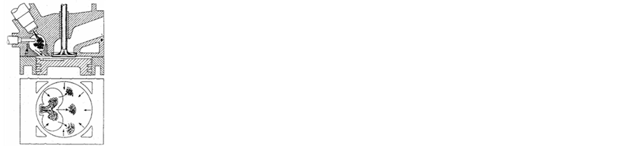

Figure 1. Fuel-air mixture formation and combustion process in a COMET type pre-combustion chamber engine.


Figure 2. Fuel-air mixture formation and combustion process in a MAN-M-Process type engine.
![]()
Figure 3. Optimum combustion, MR-1 combustion chamber [15] .
The basic difference of the MR-1 combustion chamber from the classical w shaped chambers is the smearing of the fuel to the chamber walls as in the MAN-M-Process or layered mixing.
Double whirl MR-2 combustion chamber design, also named as MR-Process is a combination of Ricardo-COMMET and M-Process concepts. Schematic illustration of the concept chamber is given in Figure 4.
R. Mehdiyev (Mehdiyev, et al. [12] ) has several patents related to the above MR-Process MR-1 and MR-2 combustion chamber designs. A new phase of MR-2 application is experimentally designed.
In the present study, work has been carried out to analyze Cold Flow characteristics (Martinas G. et al. [13] , Pathak Yogesh R, et al. [14] ) of the experimental design to enable insight into the results obtained and further research capabilities. Results obtained indicate that MR-2 type chamber design may increase the combustion quality of the Internal Combustion Engine.
3. Computational Fluid Mechanics Analysis
In the present study, geometric model of the engine and cylinder assembly, developed in CATIA environment is transferred and simplified for computational fluid mechanics analysis in ANSYS_FLUENT environment.
3.1. Geometric Modeling
The computer aided design of the piston and piston head of the MR-2 experimental combustion chamber design is shown in Figure 5. Piston diameter is 14 mm, stroke is 115 mm and the piston rod length is 209.6 mm.
Computational domain covers the exhaust and suction channels as shown in Figure 6. The boundaries are selected to be at the end of the manifolds. The valves are selected to move within the channel boundaries as illustrated by solid circles inside the channels.
Figure 7 and Figure 8 show, respectively, the exhaust channel and combustion chamber tetrahedral element meshed geometries as examples of meshing structure.
3.2. Physical Modeling
In the physical modeling phase, k-ε2-equation turbulence model is used together with a coupled energy equation solution. A diesel-air mixture model is adopted for a diesel fuel of 730 kg/m3 specific mass and a viscosity of 0.0024 kg/m-s. Wall film model is used for combustion chamber boundaries.
Discrete phase model is adapted for injection and mixture formation phases. 4 injection points are defined with 0.0123 kg/s injection starting at 714 Crank Angle and ending at 732 Crank Ankle (CA).
Dynamic mesh model uses 2500 rpm speed starting at 360 CA and ending at 720 CA with a step size of 0.5 degrees. Piston stroke is 115 mm with a connecting rod length of 209.6 mm. Piston stroke cutoff is set at 15 mm.
3.3. Mathematical Modeling
Solutions of pressure and velocity field is obtained by using the SIMPLE algorithm (Url-1 (Fluent, [15] ) where fluid properties like density and viscosity and turbulent viscosity are updated, discretized momentum equations are iteratively solved and pressure equations are solved using the newly obtained vector fields and pressure and mass distributions are updated based on the last iteration. The energy equation and the turbulence quantities are also solved for new scalar quantity field construction.
Source terms are evaluated based on the effect of phase differences and are updated. Iterations are followed and convergence is tested to obtain a solution in every step.
![]()
![]()
Figure 4. MR-2 combustion chamber schematic illustration and combustion characteristics (white areas (yellowish in colored form) indicate high temperature and thus flame propagation).
![]()
Figure 5. MR-2 piston 3D model.
![]()
![]()
Figure 6. Exhaust and suction channels and valve boundaries for computational purposes.
![]()
Figure 7. Suction channel mesh structure: 78,021 tetrahedral elements with 14,872 nodes.
![]()
Figure 8. Combustion chamber mesh structure: 85,055 tetrahedral elements with 18,049 nodes.
Geometric change attributions together with the convergence process for each iteration require large amounts of data storage, manipulation and process time.
4. Results
Data obtained in the present work requires extensive post processing work and analysis. Figure 9 shows resultant velocity field distribution at a section of the cylinder-piston assembly at 480 Crank Angle. Sections A-A, B-B and C-C are shown in the figure to present the velocity field vectors along these cross sections. A section of the inlet valve and suction is also shown in the figure. The inlet valve on the right upper side of the cylinder is fully penetrated at this crank angle and the exhaust valve that can be seen on the upper left side of the cylinder is closed.
Figure 10 shows the velocity vector field distribution along section A-A in Figure 9.
![]()
Figure 9. Resultant velocity field distribution at 480 crank angle.
![]()
Figure 10. Resultant velocity vector field distribution at 480 crank angle along section A-A in Figure 9. (Tangent to the inlet valve).
Figure 11 and Figure 12 show the velocity distributions along sections B-B and C-C in Figure 9.
At 680 Crank Angle (CA) both the inlet and exit valves are closed. Figure 13 shows the velocity field distribution along a section with A-A and B-B cross sections with A-A section at same height as in Figure 9 and B-B section passing through the combustion chamber mid-section as in Figure 12.
In Figure 13 the velocity vector field along section A-A in Figure 14 is presented. The decrease in velocity values from 90 - 100 m/s to 15 - 20 m/s is easily observed together with a swirl feature.
The swirl effect within the combustion chamber is shown in Figure 15 along cross section B-B in Figure 14.
In the present study a full cycle simulation of the flow field within the cylinder of a diesel engine is presented. In order to accurately assess the swirl and turbulence development in a novel twin swirl combustion chamber

Figure 11. Resultant Velocity vector field distribution at 480 crank angle along section B-B in Figure 9. (mid-section).

Figure 12. Resultant Velocity vector field distribution at 480 crank angle along section C-C in Figure 9. (combustion chamber mid-section).

Figure 13. Resultant Velocity vector field distribution at 680 crank angle at section A-A in Figure 13. (valve end diving point).

Figure 14. Resultant velocity field distribution at 680 crank angle.

Figure 15. Resultant Velocity vector field distribution at 680 crank angle along section B-B in Figure 13. (combustion chamber mid-section).
design, computations are carried out for an initial cycle to enable nearly periodic conditions for the flow. Results presented in this paper are snap-shots of the flow field at various characteristic cross sections.
5. Conclusions
Experimental results for the Twin Swirl “MR Process” are presented by Mehdiyev, et al. [16] in pursuit of conversion of diesel engines to operate with gaseous fuels. Present study is focused on Cold Flow characteristics of the above mentioned and present findings indicate the level of improvement in flow characteristics.
The level of turbulence and smearing of the fuel to the walls of the chamber are expected to increase efficiency and achievement of optimum combustion parameters.
The present work is expected to reveal information to the experimental study carried out in parallel to enable optimum injection parameters and angles.
Although the original efforts have taken long computation and pre-post processing hours, dependable solutions obtained in the present study is expected to contribute to computational efforts in the injection and combustion phases as initial conditions.
Acknowledgements
The authors would like to extend their sincere thanks to Prof. Rafig Mehdiyev for his contributions throughout the entire study and to the specific information related to their ongoing novel development work. Special thanks to Enis Ozcan (PhD) in his invaluable contributions in the course of the calculation efforts.
Cite this paper
Doğan Güneş,Mehmet Serkan Horasan, (2016) Full Cycle Cold Flow Analysis of the Effect of Twin Swirl Combustion Chamber Design in a Diesel Engine. World Journal of Mechanics,06,109-117. doi: 10.4236/wjm.2016.64009
References
- 1. Andersson, Ö., Somhorst, J., Lindgren, R., Blom, R. and Ljungqvist, M. (2009) Development of the Euro 5 Combustion System for Volvo Cars 2.4L Diesel Engine. SAE Technical Paper 2009-01-1450.
- 2. Zolver, M., Griard, C. and Henriot, S. (1997) 3D Modeling Applied to the Development of a DI Diesel Engine: Effect of Piston Bowl Shape. SAE Technical Paper 971599.
- 3. Wickman, D., Senecal, P. and Reitz, R. (2001) Diesel Engine Combustion Chamber Geometry Optimization Using Genetic Algorithms and Multi Dimensional Spray and Combustion Modeling, SAE Technical Paper 2001-01-0547.
- 4. Joo, K. and Lee, J. (2003) In-Cylinder Flow Field Analysis of a Single Cylinder DI Diesel Engine Using PIV and CFD. SAE Technical Paper 2003-01-1846.
- 5. Meingast, U., Staudt, M., Reichelt, L. and Renz, U. (2000) Analysis of Spray/Wall Interaction under Diesel Engine Conditions. SAE Technical Paper 2000-01-0272.
- 6. Christensen, M. and Johansson, B. (2002) The Effect of In-Cylinder Flow and Turbulence on HCCI Operation. SAE Technical Paper 2002-01-2864.
- 7. Christensen, M., Johansson, B. and Hultqvist, A. (2002) The Effect of Combustion Chamber Geometry on HCCI Operation. SAE Technical Paper 2002-01-0425.
- 8. McLandress, R., Emerson, R., McDowell, P. and Rutland, C. (1996) Intake and In-Cylinder Flow Modeling Characterization of Mixing and Comparison with Flow Bench Results. SAE Technical Paper 960635.
- 9. Url-2, Ricardo (2012)
http://g.eng.cam.ac.uk/125/achievements/ricardo - 10. Taylor, C.F. (1968, 1977, 1985) The Internal Combustion Engine in Theory and Practice. MIT Press, Cambridge, MA, Vol. 2.
- 11. Mehdiyev, R., Sorusbay, C., Özgür, L., Arslan, H. and veKutlar, A. (2006) Dizelmotorlarlnlngelistirilmesinin alternative biryolu, 3. OtomotivTeknolojileriKongresi, Bursa, 26-28 Haziran 2006.
- 12. Mehdiyev, R., Derbentli, T., Arslan, H., Özcan, E. and Potur, R.A. (2009) Development of a Turbo Diesel Engine by a New Combustion Process for Heavy Duty Vehicles and Tractors. 9th International Conference on Engine and Vehicle, SAE International, 13 September 2009.
- 13. Martinas, G., Cupsa, O.S., Stan, L.C. and Arsenie, A. (2015) Cold Flow Simulation of an Internal Combustion Engine with Vertical Valves Using Layering Approach. Modern Technologies in Industrial Engineering (ModTech2015) IOP Conf. Series: Materials Science and Engineering, 95, 012043.
- 14. PathakYogesh, R., DeoreKalias, D. and PatilVijayenda, M. (2014) In Cylinder Cold Flow CFD Simulation of IC Engine Using Hybrid Approach. International Journal of Research in Engineering and Technology, 3, NCAME-2014, June-2014, 16-21.
- 15. Url-1, Fluent (2010)
https://www.sharcnet.ca/Software/Fluent6/html/ug/main_pre.htm - 16. Mehdiyev, R., Ogun, K., Ozcan, E., Arslan, H., et al. (2011) The Twin Swirl “MR-Process” Combustion Mechanism and Conversion of Diesel Engines to Operate with Gaseous Fuels. SAE Technical Paper 2011-24-0066.