World Journal of Mechanics
Vol.3 No.7(2013), Article ID:37979,8 pages DOI:10.4236/wjm.2013.37031
Stress-Strain State in Elastic Body with Physical Cut
Department of Mathematical Modelling, Tula State University, Tula, Russia
Email: vadim@tsu.tula.ru
Copyright © 2013 Vadim Vadimovich Glagolev, Alexey Alexandrovich Markin. This is an open access article distributed under the Creative Commons Attribution License, which permits unrestricted use, distribution, and reproduction in any medium, provided the original work is properly cited.
Received August 2, 2013; revised September 3, 2013; accepted September 28, 2013
Keywords: Crack; Physical Cut; Characteristic Size
ABSTRACT
We consider the problem of distributing the stress-strain state (SSS) characteristics in the body arbitrarily loaded on the outer surface and weakened by a physical cut with a thickness of . It is assumed that
  parameter is the smallest possible size permitting the use of the hypothesis of continuity. The continuation of the physical cut divides the body into two parts interacting with one another by means of a contact with
  -layer. Due to constant average stresses and strains over the layer thickness, the problem reduces to the system of variational equations for the displacement fields in the adjacent bodies. The geometry of the bodies under consideration has no singular points and, as a consequence, has no singularity of stresses. The use of average characteristics makes it possible to disregard a form of the physical cut end. The obtained solution can be used for processing of experimental data in order to establish the continuity scale
 . The entered structure parameter for silicate glass is assessed using known mechanical characteristics.
1. Introduction
Strength calculations for structural parts and elements with various stress concentrators as part of the classical concepts of continuum mechanics (CM), as a rule, lead to unreal stress values in the neighbourhood of singular points in terms of strength characteristics. This is caused by the use of the hypothesis of continuity. While the cut curvature radius is large enough in comparison with the crystals of the matter, it has no effect on the stress distribution, but if the curvature is commensurate with the crystal sizes, the questions arise of whether it is reasonable to use the classical theory of elasticity.
Note that the crack in a solid body naturally generates a stress concentrator and, in this case, consideration of the medium structure permits to eliminate some contradictions in the model representation related to the singularity of the stress field in the singular points. However, the question is how to determine the average characteristics on the entered structural elements. In this case, two approaches can be distinguished. The first one [1-3] uses singular solutions of the theory of elasticity for the crack model in the form of a mathematical cut, and averaging over the entered generic element is carried out on their basis. The second one [4-7] attributes a homogeneity property of the stress-strain state (SSS) to the structural element in a particular direction (e.g., orthogonally to the supposed direction of fracture) and the coupled problem [6,7] on SSS determination, both in the structural element and in the medium adjacent to it, is solved, where CM classical solutions are deemed to be feasible. Thus, in the paper [8], a layer with characteristic thickness  is singled out assuming the strain homogeneity through its thickness in the crack development trajectory. However, the paper [8] does not include
  parameter estimations and statements of the relevant problems.
The model presenting the crack as a physical cut with a thickness of  is proposed in the papers [4-8] for SSS determination in the bodies with cracks. In addition, the model also includes a material layer on the extension of the cut. Material adjacent to the layer can be regarded within the framework of the classical CM concepts, using the layer boundary stresses as boundary conditions. The stress state of the layer is described by average and boundary stresses connected by equilibrium conditions [6,7]. The use of the average characteristics allows not considering the geometry of the physical cut transition to the material layer. Defining relations within the layer are considered for average stresses and strains. The singularity of the physical cut model can be excluded by introducing a definite form of its end, i.e. a part of a circle or an ellipse. However, this case raises the question of the corresponding curvature radiuses. The book [9] determines an experimental dependence of КIC on the sharpness (curvature radius of the notch base) of the stress concentrator. The obtained dependence shows that КIC quickly falls with a decrease in the notch base radius until it reaches some threshold value. The further decrease in the curvature radius has no effect on КIC characteristic. It demonstrates the presence of some typical size which would make the fracture beginning independent of the cut end geometry. In our situation, the physical cut thickness is associated with this typical size, so there’s no point in discussing a form of its end. The introduction of average characteristics over the layer thickness makes it possible to dismiss the questions related both to infinite stresses on the physical cut extension in the continuous medium and to a form of the physical cut end, so the corresponding boundaries are shown in Figure 1 with a wavy line. The boundary stresses associated with average equilibrium conditions [6] are also considered for the layer. The layer/medium conjunctions are established by the layer boundary stresses on the surface which has no singular points and, as a consequence, has no singularity. The article [7] includes solutions for infinite linear-elastic medium with the physical cut. The paper [6] for perfectly elastoplastic behavior of the layer material solves the analogue of the Dugdale problem [10]. This article provides general statement of the problem of damaged finite body straining.
2. Problem Statement
Let us consider loading of the finite body with the physical cut with a length of а and a thickness of  according to the diagram in Figure 1. The X-axis of the Cartesian system is to be associated with the direction of the cut, and the reference point is to be associated with its middle. Following the model presentation [4-7], let us consider the material layer overlying the extension of the physical cut. The corresponding areas are numbered 3

Figure 1. Loading scheme.
and 4 in Figure 1. Let us consider that distributed external load  is imposed on parts of the body surface, and load
  is imposed on the ends of the physical cut.
Let us use the following designations for the layer boundary stresses: 

 . We assume that the stress vectors on the layer adjoint boundaries are equal and opposite to the stress vectors of the body adjoint boundaries:
 (1)
(1)
We have a rigid coupling between the boundaries:
 . (2)
. (2)
And continuous displacements along the layer boundaries. “b” index is related to the body areas adjacent to the layer.
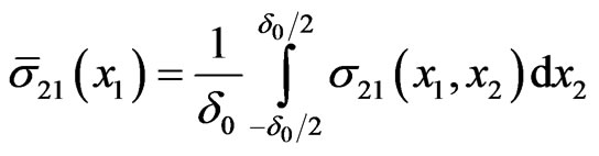
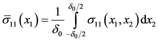
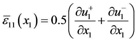
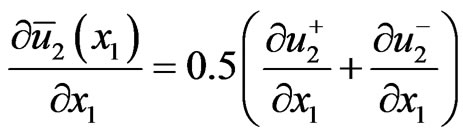
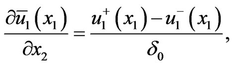
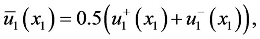
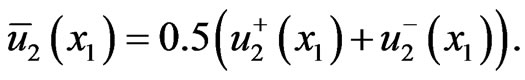
Let us define average stresses, strains and displacements in the layer using their boundary values as follows:
 , (3)
, (3)
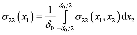 , (4)
, (4)
 , (5)
, (5)
 , (6)
, (6)
 , (7)
, (7)
 , (8)
, (8)
 (9)
(9)
 (10)
(10)
 (11)
(11)
We derive the expression of average shear strain along the layer from the expressions (8) and (9):
 (12)
(12)
Let us consider equilibrium condition for the body dispose out of the cut, using:
 , (13)
where  is work of external surface loads;
 ,
,  ,
,  ,
,  are work of internal stresses in the relevant areas of the body.
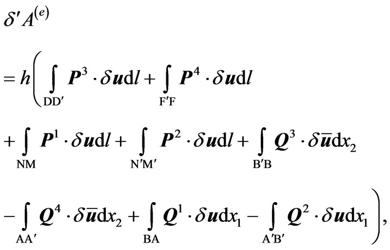 (14)
(14)
where  is vector of mean displacements on the cut end; h is body thickness in the direction orthogonal to the plane
 .
.
On the basis of the formulae (10), (11), the expression (14) may be written as:
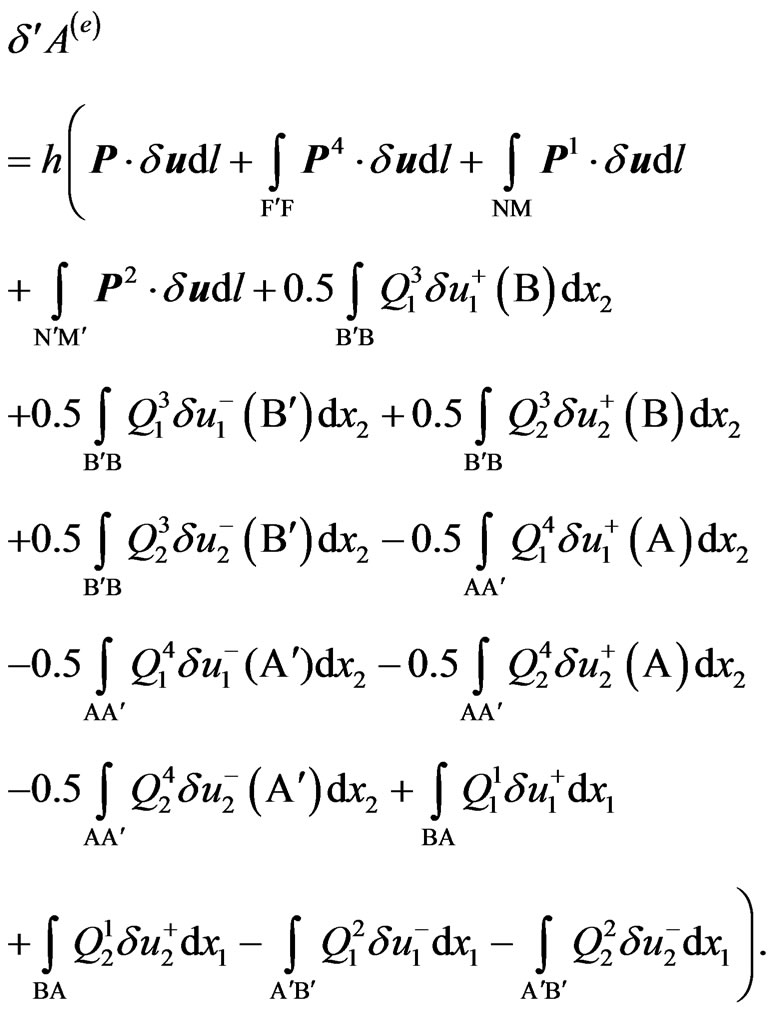 (15)
(15)
Let us consider the work of internal stresses in area 3:
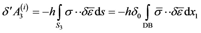 (16)
(16)
where  are tensors of the layer average stresses and strains;
  is layer area BD’DB’
Using expressions (6), (7), (12) and the symmetry of the average stress and strain tensor ( ,
, ), the work (16) may be presented as:
 (17)
(17)
The work of the internal stresses in area 4 may be obtained in a similar way:
 (18)
(18)
Using the system (13) - (18), we obtain:
 (19)
(19)
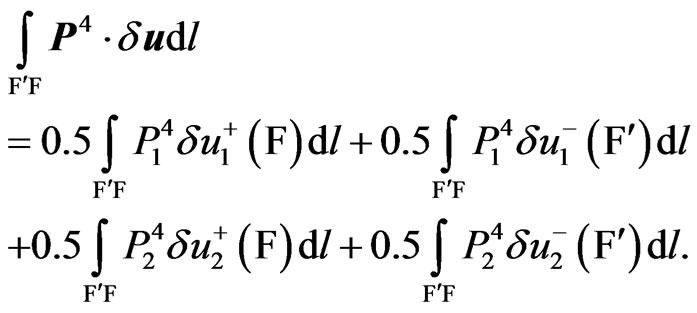
The work of the distributed external load  may be presented as:
Using (10), (11), we can derive from the last equation
 (20)
(20)
On the analogy with (20), the distributed external load  may be presented as:
 (21)
(21)
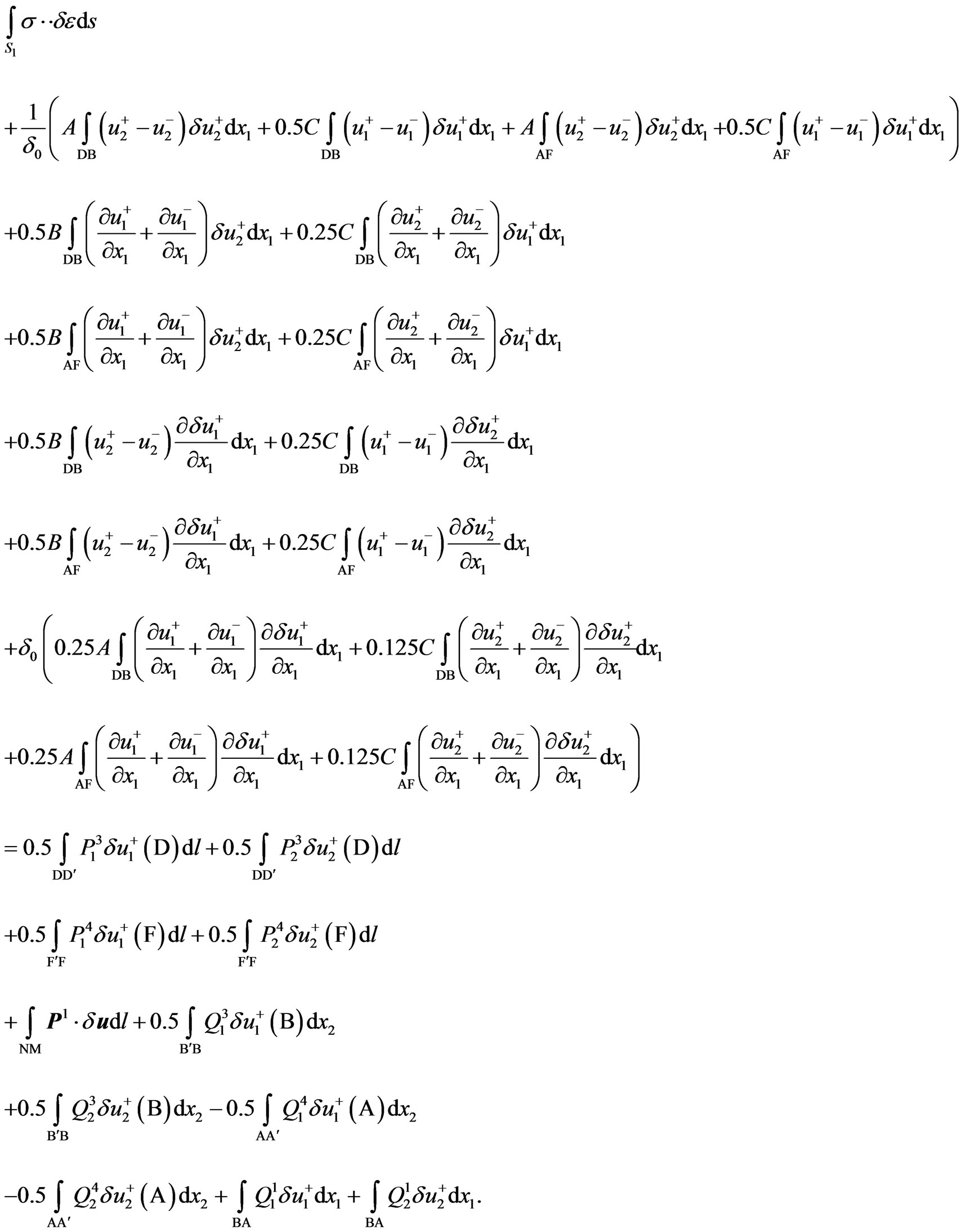
With regard to (20) and (21), the expression (19) falls into two variational equations of equilibrium. For body1:
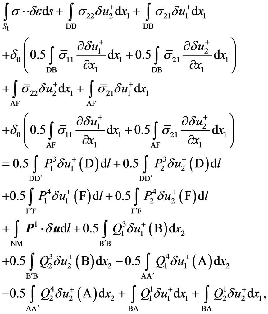 (22)
(22)
and for body 2:
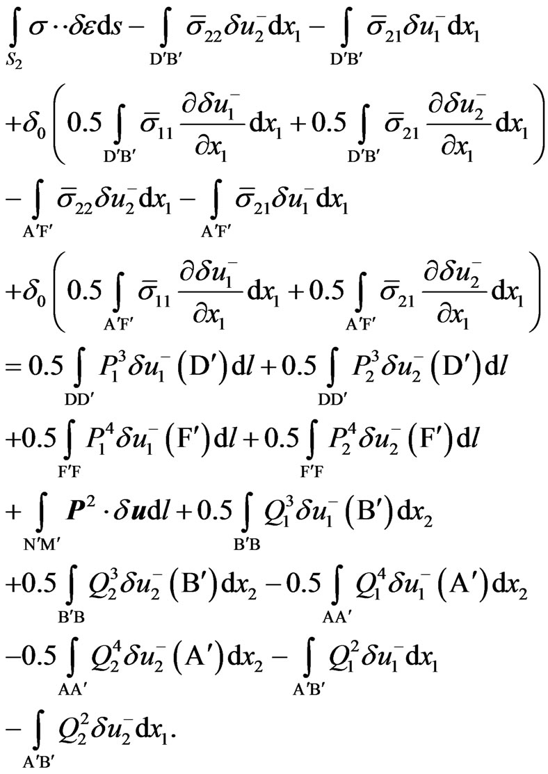 (23)
(23)
For the layer material, the relations between the average stresses and strains may be presented in the form of Hooke’s law for the case of plane strain:
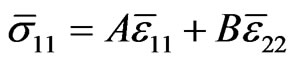 (24)
(24)
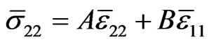 , (25)
 , (26)
where
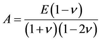 ,
, 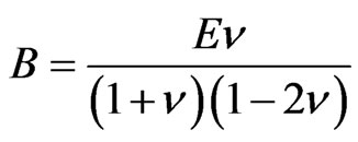 ,
, 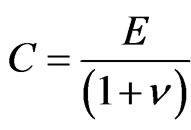 , E is Young’s modulus,
  is Poisson’s ratio.
Relations (24)-(26) with regard to the expressions (6), (7), (12) may be substituted in (22).
Let us group the summands in the expression in relation to :
:
 (27)
(27)
Relation (23) may be written in a similar way:
 (28)
(28)
Specific virtual work of stresses in the bodies 1 and 2 located outside the layer is determined in accordance with Hooke’s law (24)-(26) through the displacement field as follows:
 (29)
(29)
The system of variational Equations (27) and (28) with regard to the expression (29) allows us to determine the displacement field in the bodies 1 and 2 including displacement  along the boundaries of the layer. The finite element method seems to be the most obvious way of solution this problem.
3. Determination of the Characteristic Size
The main problem of the proposed statement is the determination of . Alternatively, the entered parameter may be found using the scheme of loading with concentrated load as shown in Figure 2 for brittle materials.
Due to the problem symmetry, it is sufficient to consider one half of the body 1. In this case, we have the following conditions for the layer boundaries:
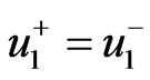 , (30)
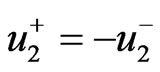 . (31)
With regard to the conditions (30) and (31), the variational relation (27) for the right half of the body 1 may be written as:
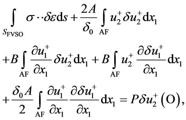 (32)
(32)
Under the following boundary conditions:
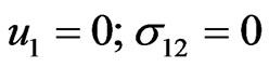 on SO (symmetry conditions) (33)
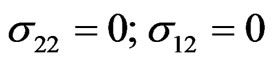 on VS (free-surface conditions) (34)
 on FV (free-surface conditions) (35)
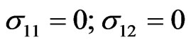
 on OA (free-surface conditions) (36)
When solving the system (32)-(36) under given  and
and , we can find the SSS distribution both over the body limited by FVSO contour, and over the adjacent layer.
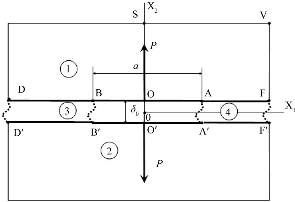
Figure 2. Scheme of loading with concentrated load.
To define a value , we can use the linear relationship in the elastic field between power P and SSS characteristics in the local area. We can adopt strain
  or stress
  in the end zone
 , as well as displacements of the force points
  as these characteristics. Let us assume that local rigidity is found in the experiment
 where
where  is experimentally determinable force value,
  is relevant displacement of point О.
By solving the Equation (27), we find the value of the set local rigidity depending on the layer thickness - . Given that
 , we can find
 .
.
We failed to find the initial experimental data to determine the rigidity  in the available literature. Therefore, we offer an indirect method for determination on the basis of the known values of fracture toughness
  and critical stress
 .
.
It is known that stress intensity coefficient for the diagram in Figure 2 is defined by the formula [11]:
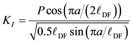 where
where  is sample length.
Thus, critical force may be found by the formula:
 . (37)
For silicate glass: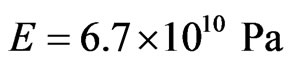 ,
, 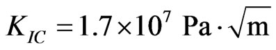 [11]. Let us consider a sample (see Figure 2) with the following dimensions:
 ,
,  ,
, . Using the formula (37), we determine:
 . Figure 2
shows the dependence of breaking stress in the cut top on parameter  for critical force found in the Equation (32) obtained by means of the finite element method. We used the quadratic approximation of the displacement field on the element, the element size in the neighbourhood of point O was equal
 .
.
Glass breaking strength, following the paper [12], varies from 1.5 × 10⁷ Pa for severely damaged glass to 1500 × 107 Pa for undamaged glass. Furthermore, the latter value is close to the lower limit of the theoretical strength of glass, which varies within . It is known that the glass tensile strength is 15 - 20 times less than the compression strength. The review [12] includes the bend loading of acid-etched glass rod to stress
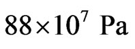 . Further, we assume that tensile strength of the defect-free glass is
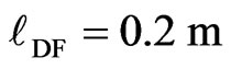
 . In this case, using Figure 3, we obtain a structure parameter
 . Note that the obtained value corresponds to a linear size of the Neuber particle, which is equal to about half a millimeter as shown in the paper [3]. The article [4] contains the following relationship for brittle materials:
 , which gives a somewhat higher result:
 .
.
4. Conclusion
Based on the results of the interactive layer thickness experiments for specific elastic materials, using the system of Equations (27) and (28), we can find the distribution of SSS characteristics in the finite body with a crack in the form of the physical cut. The proposed model allows performing calculations for arbitrary external load. This approach allows us to avoid the singularity of stresses and strains in the crack end in contrast to the classical representation of the crack in the form of the mathematical cut.
5. Acknowledgements
This work was supported by the Russian Foundation for
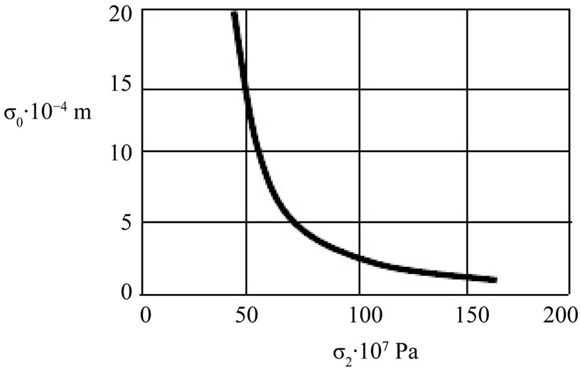
Figure 3. Dependence of breaking stress in the cut top on parameter δ0 for critical force.
Basic Research (Grant Nos. 13-08-00134 and 13-01- 97501).
REFERENCES
- F. A. McClintock, “Ductile Instability in Shear,” ASME Journal of Applied Mechanics, Vol. 25, 1958, pp. 582- 588.
- F. A. McClintock, “On the Plasticity of the Growth of Fatigue Cracks,” In: Fracture of Solids, John Wiley & Sons Inc., New York, 1963.
- H. Neuber, “Kerbspannungslehre: Grundlagen für Genaue Spannungsrechnung,” J. Springer, Madison, 1937.
- M. V. Gavrilkina, V. V. Glagolev and A. A. Markin, “Solution of One Problem of Fracture Mechanics,” Journal of Applied Mechanics and Technical Physics, Vol. 48, No. 4, 2007, pp. 571-576. http://dx.doi.org/10.1007/s10808-007-0072-1
- V. V. Glagolev and A. A. Markin, “On a Method for the Establishment of between the Critical Values of the Characteristics of Steady-State Material Separation Process,” Strength of Materials, Vol. 38, No. 2, 2006, pp. 141-149. http://dx.doi.org/10.1007/s11223-006-0026-5
- V. V. Glagolev and A. A. Markin, “Propagation of Thin Plastic Zones in the Vicinity of a Normally Separating Crack,” Journal of Applied Mechanics and Technical Physics, Vol. 50, No. 5, 2009, pp. 901-910. http://dx.doi.org/10.1007/s10808-009-0122-y
- V. V. Glagolev and A. A. Markin, “Finding the Elastic Strain Limit at the Tip Region of a Physical Cut with Arbitrarily Loaded Faces,” Journal of Applied Mechanics and Technical Physics, Vol. 53, No. 5, 2012, pp. 784-792. http://dx.doi.org/10.1134/S0021894412050185
- F. A. McClintock, “Fracture: An Advanced Treatise,” Academic Press, Waltham, 1971.
- J. F. Knott, “Fundamentals of Fracture Mechanics,” Butterworths, London, 1973
- D. S. Dugdale, “Yielding of Steel Sheets Containing Slits,” Journal of the Mechanics and Physics of Solids, Vol. 8, No. 2, 1960, pp. 100-104.
- G. P. Cherepanov, “Mechanics of Brittle Fracture,” McGraw-Hill, New York, 1979.
- C. J. Philips, “Fracture: An Advanced Treatise,” Academic Press, Waltham, 1972.