World Journal of Condensed Matter Physics
Vol.2 No.4(2012), Article ID:24398,4 pages DOI:10.4236/wjcmp.2012.24028
TM Waves Propagation at Magnetoplasma-MTMs Interface
![]()
1Physics Department, Al-Aqsa University, Gaza, Palestine; 2Electrical Engineering Department, Islamic University of Gaza, Gaza, Palestine; 3Physics Department, Islamic University of Gaza, Gaza, Palestine; 4Technical University Munich, Instutite for Measurement Systems and Sensor Technology, München, Germany.
Email: hkhozondar@iugaza.edu
Received July 5th, 2012; revised August 6th, 2012; accepted August 14th, 2012
Keywords: Magnetoplasma; Metamaterials; Submilimeter Waves; Isolator; Nonreciprocal Components
ABSTRACT
A new structure for isolator is proposed in this work. The proposed structure consists of metamaterial-magnetoplasma semiconductors parallel plate structure. The utility of magnetoplasma semiconductors is promising in developing nonreciprocal components in the submillimeter-wave and millimeter-wave bands for satellite communications. Metamaterials (MTMs) is used to enhance the behavior of the isolator.
1. Introduction
Isolators are needed in advanced satellite communications application in submillimeter wave energy bands with wavelength ranges between 1000 - 100 μm (300 GHz - 3 THz). Isolators use the TMo mode only, the effective refractive index of which is different for forward and backward propagation, if the magnetization is properly adjusted [1]. The design and fabrication of isolators in the millimetric and submillimetric regions using properties of magnetoplasmons in semiconductors have been reported [2]. Metamaterials (MTMs) known as lefthanded substances are substances with simultaneous negative permittivity and permeability. The permittivity and the permeability are the only parameters of the substance that appear in the dispersion equation; therefore, they are the basic characteristic magnitudes which control the propagation of electromagnetic waves in matter. Authors [3,4] used MTMs in fabrication of isolators in combination of ferrite martials, garnet. However, there is a draw back for garnet that it has narrow bands at frequencies above 40 GHz due to the maximum saturation magnetization. This motivated several authors to investigate analytically and experimentally surface wave behavior along single gyroelectric or isotropic semiconductor interface [5-8] for purpose of isolator application. In this work, authors studied the possibility of enhancing the isolator behavior by studying the surface wave at the interface between semiconductor and MTMs. Further, the authors studied the behavior of the isolator at the vicinity of extraordinary wave resonance (EWR) which is an electromagnetic wave, partly transverse and partly longitudinal, which propagates perpendicular to applied magnetic field B. Next section introduces the basic theory of the proposed model. Numerical analysis is introduced in Section 3. The conclusion is given in Section 4.
2. Basic Theory
2.1. The Model
The geometry of the proposed configuration is displayed schematically in Figure 1. The direction of an external magnetic field is perpendicular to the direction of wave propagation in the waveguide. The structure comprises a semiconductor gallium arsenide (GaAs) substrate and a cover made of MTM.
The semiconductor is considered to be GaAs. The Drude-Zener model is applied to describe the interaction between the magnetically biased semiconductor and the field. In this work, the plasma or the ionic medium is characterized by the scalar permeability μ0 and the fol-
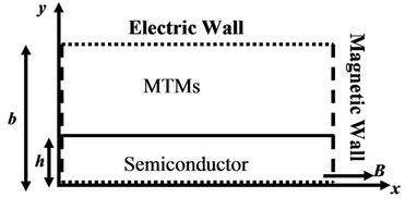
Figure 1. Inhomogeneous magnetoplasma semiconductor parallel plate waveguide.
lowing relative permittivity tensor [9]:
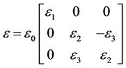 (1)
(1)
where
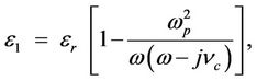
 ,
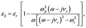
,  ,
,  ɛr is the relative permittivity, ω is the angular frequency, ωp is the electron plasma frequency, ωc is the cyclotron frequency, νc is the collision frequency, Ne is the density of nearly free electrons in the semiconductor, me* is the effective electron mass, μe is the electron mobility and B is the applied magnetic flux density. In the Drude-Zener model the cyclotron frequency must be greater than the collision frequency. In the lossless case, νc = 0 the tensor entries reduces to
 (2)
(2)
 (3)
(3)
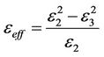
Equations (2) and (3) show that there is a singularity at ω = ωc. The Gyroelectric ratio, ε3/ε2, is defined as follows
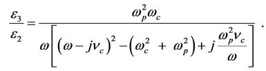 (4)
(4)
Metamaterials (MTMs) has both negative permittivity εm and negative permeability µm. Both εm and µm are function of frequency as follows [10]
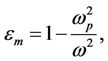 (5)
(5)
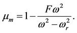 (6)
(6)
In this work, we consider both εm and µm linear and lossless. The values of the parameters ωr, ωp, and F are chosen such that εm < 0 and µm <0.
2.2. Fields and Field Equations
In this study we only considered transverse magnetic fields (TM). The TM fields are assumed to have the following forms:
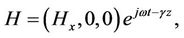 (7)
(7)
where γ = α + jβ is the complex propagation constant. Applying Equations (7) and (8) into Maxwell’s equations we get the field equation for each medium. We can get the dispersion Equation (9) by applying the boundary conditions at y = 0, i.e. Ez and Hx must be continuous.
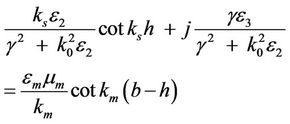 (8)
(8)
where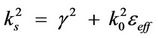 , k0 is the wave number is free space,
 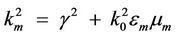 , b is the total thickness of the waveguide, h is the thickness of the semiconductor layer as indicated in Figure 1, and
 (9)
(9)
In Equation (9), squaring γ gives linear term of the propagation constant β and second order term of β. The linear term of β made it possible to have an isolator from the proposed configuration.
3. Numerical Analysis
Equation (5) is numerically plotted in Figure 2 which
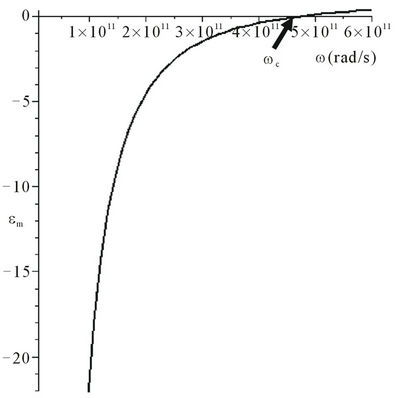
Figure 2. MTMs permittivity (εm) is plotted as function of frequency (ω).
shows the permittivity εm of MTMs as function of frequency (ω). We notice that εm is negative for ω < ωp = 150 π = 471.2 GHz. The permeability µm of MTMs, Equation (6) is plotted as function of frequency (ω) in Figure 3, we notice that µm is negative for 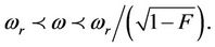
The real and imaginary parts of the effective permittivity as function of frequency are shown in Figure 4. In
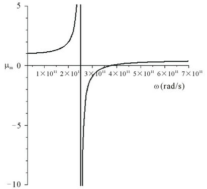
Figure 3. Dependence of MTMs permeability (µm) on frequency (ω).
Figure 4. The real and imaginary parts of the effective permittivity are plotted versus frequency.
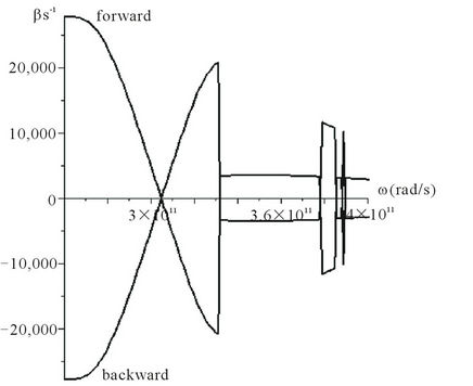
Figure 5. Variation of forward and backward propagation with frequency (ω).
the calculation we choose the value of collision frequency , the value of cyclotron frequency
 . The values are chosen such that the Drude-Zener condition is satisfied. That is ωc > νc. Figure 4 shows the extraordinary wave resonance (EWR) occurs at
 . This is the region of our interest.
The dispersion Equation (9) is solved numerically. The forward and backward wave propagation is plotted as function of frequency as exhibited in Figure 5. In the calculation, b = 80 µm and h = 1/8 b.
It can be seen from Figure 5 that in the vicinity of the EWR the forward and backward propagation exhibits nonreciprocal effect. The maximum difference between both directions of propagation (forward and backward) occurs at frequency ω = 257 GHz.
4. Conclusion
We proposed a two layer system for an isolator. The proposed structure consists of semiconductor substrate and MTMs cover. The proposed structure exhibits a nonreciprocal device at the vicinity of EWR. The maximum phase difference occurs at 257 GHz.
REFERENCES
- H. Hemme, H. Dotsch and P. Hertel, “Integrated Optical Isolator Based on Nonreciprocal-Mode Cut-Off,” Applied Optics, Vol. 29, No. 18, 1990, pp. 2741-2744. doi:10.1364/AO.29.002741
- D. M. Bolle and S. H. Talisa, “Fundamental Consideration in Millimeter and Near-Millimeter Component Design Employing Magnetoplasmons,” IEEE Transactions on Microwave Theory and Techniques, Vol. 29, No. 9, 1981, pp. 916-923. doi:10.1109/TMTT.1981.1130474
- H. El-Khozondar, R. El-Khozondar and M. Shabat, “Coupling Efficiency of Magnetooptical Integrated Isolator,” International Journal of Modern Physics B, Vol. 23, No. 22, 2009, pp. 4675-4683. doi:10.1142/S0217979209053655
- R. El-Khozondar, H. El-Khozondar and M. Shabat, “Applications of Metamaterials in Optical Waveguide Isolator,” Proceedings of the Metamaterials III Conference of SPIE, Strasbourg, 7-10 April 2008, pp. 1-8.
- K. W. Chiu and J. J. Quinn, “Magnetoplasma Surface Waves in Polar Semiconductor: Retardation Effects,” Physical Review Letters, Vol. 29, No. 9, 1972, pp. 600-603. doi:10.1103/PhysRevLett.29.600
- J. J. Brion and R. F. Wallis, “Theory of Surface Magnetoplasomons in Semiconductor,” Physical Review Letters, Vol. 28, No. 22, 1972, pp. 1455-1458.
- M. S. Kushwaha and P. Halevi, “Splitting of Surface Polaritons Dispersion Curves Due to Resonance with Magnetoplasma Transition Layer,” Solid State Communications, Vol. 64, No. 11, 1987, pp. 1405-1408. doi:10.1016/0038-1098(87)90402-9
- V. H. Mok and L. E. Davis, “Nonreciprocal GaAs PhaseShifters and Isolators for Millimetric and Sub-Millimetric Wavelengths,” Proceedings of MTT-S International Microwave Symposium 3 of the IEEE, Philadelphia, 8-13 June 2003, pp. 2249-2252.
- A. A. Bulgakov and O. V. Shramkova, “Investigation of Reflection Coefficient on Semiconductor Superlattice Placed into Magnetic Field,” Semiconductors, Vol. 34, No. 6, 2000, pp. 712-716. doi:10.1134/1.1188056
- I. V. Shadrivov, A. A. Sukhorukov, Y. S. Kivshar, A. A. Zharov, A. D. Boardman and P. Egan, “Nonlinear Surface Waves in Left-Handed Materials,” Physical Review E, Vol. 69, No. 1, 2004, Article ID: 016617. doi:10.1103/PhysRevE.69.016617