International Journal of Astronomy and Astrophysics
Vol.3 No.1(2013), Article ID:29400,7 pages DOI:10.4236/ijaa.2013.31001
Wave Optics and Image Formation in Gravitational Lensing
Department of Physics, Graduate School of Science, Nagoya University, Nagoya, Japan
Email: nambu@gravity.phys.nagoya-u.ac.jp
Received January 23, 2013; revised February 24, 2013; accepted March 2, 2013
Keywords: Wave Optics; Image Formation; Gravitational Lens
ABSTRACT
We investigate image formations in gravitational lensing systems using wave optics. Applying the Fresnel-Kirchhoff diffraction formula to waves scattered by a gravitational potential of a lens object, we demonstrate how images of source objects are obtained directly from wave functions without using a lens equation for gravitational lensing. As an example of image formation in gravitational lensing, images of a point source by a point mass gravitational lens are presented. These images reduce to those obtained by a ray tracing method in the geometric optics limit.
1. Introduction
Gravitational lensing is one of predictions of Einstein’s general theory of relativity and many samples of images caused by gravitational lensing have been obtained observationally [1]. Light rays obey null geodesics in curved spacetime and they are deflected by gravitational potential of lens objects. In weak gravitational field with thin lens approximation, a path of a light ray obeys so called lens equation for gravitational lensing and many analysis concerning the gravitational lensing effects are carried out based on this equation. Especially, we can obtain images of source objects by solving the lens equation using a ray tracing method. As a path of light ray is derived as the high frequency limit of electromagnetic wave, wave effects of gravitational lensing become important when the wavelength is not so much smaller than the size of lens objects and in such a situation, we must take into account of wave effects. For example, when we consider gravitational wave is scattered by gravitational lens objects, the wave effect gives significant impact on the amplification factor of intensity for waves [2-4]. Another example that wave effects must be taken into account is direct detection of black holes via imaging their shadows [5,6]. The apparent angular size of black hole shadows are so small that their detectability depends crucially on the angular resolution of telescopes, that is determined by diffraction limit of image formation system. Thus, for successful detection of black hole shadows, it is important to investigate wave effects on images of black holes.
Although interference and diffraction of waves by gravitational lensing has been discussed in connection with amplification of gravitational waves, a little was discussed about how images by gravitational lensing are obtained based on wave optics. For electromagnetic wave, E. Herlt and H. Stephani [7] discussed the position of images by a spherical gravitational lens evaluating the Poynting flux of scattered wave at an observer. They claimed that there is a disagreement between wave optics and geometrical optics concerning the position of double images of a point source. But they have not presented complete understanding of image formation. In wave optics, image formations are understood as a diffraction effect by image forming devices such as a convex lens. The process of image formations can be expressed as a Fourier transformation of incident waves by imaging devices. In this paper, we consider image formation in gravitational lensing using wave optics and aim to understand how images by gravitational lensing are obtained in terms of waves. For this purpose, we adopt the diffraction theory of image formation in wave optics [8], which explains image formation in optical systems in terms of diffraction of waves. This paper is organized as follows. In Section 2, we review gravitational lensing using the Fresnel-Kirchhoff diffraction formula. In Section 3, we introduce a convex lens as an image formation device and apply it to the gravitational lensing system. Section 4 is devoted to summary. We use units in which  in this paper.
2. Wave Optics in Gravitational Lensing
We review the basic formalism of gravitational lensing based on wave optics [1]. In this paper, we do not consider polarization of waves and treat scalar waves as a model for electromagnetic waves. Let us consider waves propagating under the influence of the gravitational potential of a lens object. The background metric is assumed to be
 (1)
(1)
where  is the gravitational potential of the lens object with the condition
 . The scalar wave propagation in this curved spacetime is described by the following wave equation:
 (2)
(2)
and for a monochromatic wave with the angular frequency ,
,
 (3)
(3)
where  is the flat space Laplacian.
We show the configuration of the gravitational lensing system considering here (Figure 1). The wave is emitted by a point source, scattered by the gravitational potential of the lens object and reaches the observer. We assume the wave scattering occurs in a small spatial region around the lens object and outside of this region, the wave propagates in a flat space. With the assumptions of the eikonal and the thin lens approximation, the Fresnel-Kirchhoff diffraction formula provides the following amplitude of the wave at the observer [1,3]
 (4)
(4)
where  is the effective path length (eikonal) along a path from the source position
  to the observer position
  via a point
  on the lens plane
 (5)
(5)
and we assume that  and
and . A constant
  represents the intensity of a point source. The two dimensional gravitational potential is introduced by
 (6)
(6)
Then the wave amplitude at the observer can be written as [1,2]
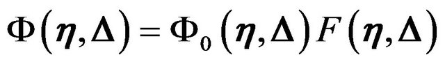 (7)
(7)
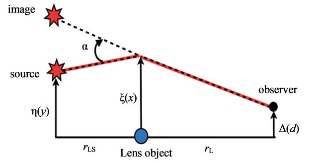
Figure 1. The gravitational lens geometry of the source, the lens and the observer.  is the deflection angle.
  is the distance from the observer to the lens object and
  is the distance from the observer to the source.
 .
.
where  is the wave amplitude at the observer in the absence of the gravitational potential
 :
:
 (8)
(8)
 is the path length along a straight path from
  to
to . The amplification factor
  is given by the following form of a diffraction integral
 (9)
(9)
 (10)
(10)
where  is the Fermat potential along a path from the source position
  to the observer position
  via a point
  on the lens plane. The first term in
  is the difference of the geometric time delay between a straight path from the source to the observer and a deflected path. The second term is the time delay due to the gravitational potential of the lens object. Now we introduce the following dimensionless variables:
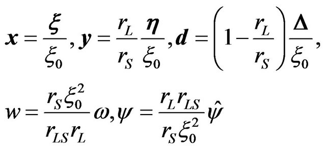 (11)
(11)
where we choose  as
as
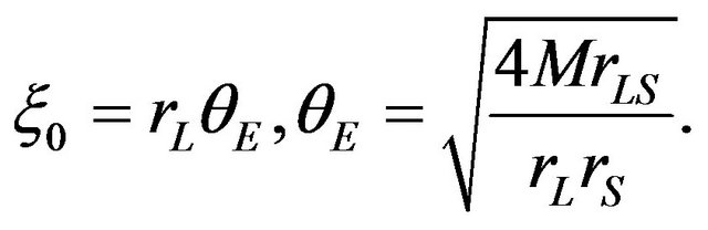 (12)
(12)
 is the mass of the gravitational source,
  and
and  represent the Einstein radius and the Einstein angle, respectively. Using these dimensionless variables,
 (13)
(13)
 (14)
(14)
In the geometrical optics limit , the diffraction integral (13) can be evaluated around the stationary points of the phase function in the integrand. The stationary points are determined by the solution of the following equation:
 (15)
(15)
This is the lens equation for gravitational lensing and determines the location of the image  for given source position
 . As the specific model of gravitational lensing, we consider a point mass as a gravitational source. In this case, the two dimensional gravitational potential is
 (16)
(16)
and the deflection angle is given by
 (17)
(17)
For , the solution of the lens Equation (15) is
 (18)
(18)
and represents the Einstein ring with the apparent angular radius  defined by (12). We show an example of images obtained as solutions of the lens Equation (15) (Figure 2). To produce these images, we have assumed an extended source with Gaussian distribution of intensity.
The wave property is obtained by evaluating the diffraction integral (13). For a point mass lens potential (16), the integral can be obtained exactly
 (19)
(19)
On the observer plane, an interference pattern appears (Figure 3). For , the asymptotic formula for the cofluent geometric function yields
 (20)
(20)
Using this formula, near , the distance between adjacent fringes of the interference pattern is
 (21)
(21)
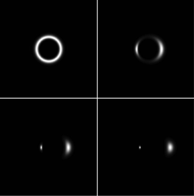
Figure 2. Images of gravitational lensing by a point mass. The source is assumed to have the intensity with Gaussian distribution. From the top left to the bottom right panels, the source positions are .
.
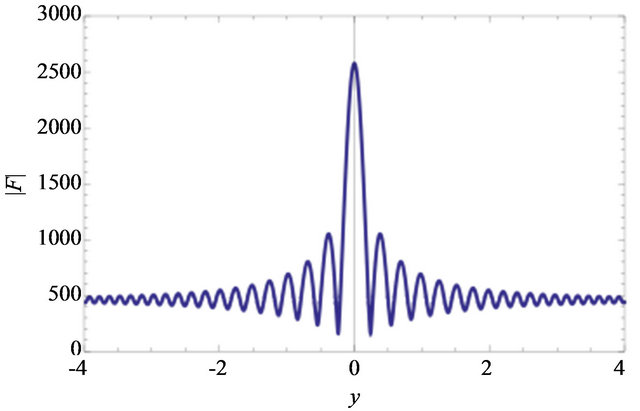
Figure 3. Amplification factor for .
.
This fringe pattern is interpreted as interference between double images of a point source by the gravitational lensing. The question we raise in this paper is how the interference pattern on the observer plane is related to the images of gravitational lensing in the geometrical optics limit. The wave amplitude on the observer plane does not make the image of the source and we have to transform the wave function to extract images. To answer this question, we introduce a “telescope” in the gravitational lensing system and simulate observation of a star (a point source) using the telescope. With this setup, it is possible to understand how images of a source are formed in the framework of wave optics.
3. Image Formation in Wave Optics
To establish relation between the interference pattern of the wave and the images of the source in the gravitational lensing system, we first consider an image formation system composed of a single convex lens and review how images of source objects appear in the framework of wave optics [8].
3.1. Image Formation by a Convex Lens
Let us  is the incident wave from a point source in front of a thin convex lens and
  is the transmitted wave by the lens (Figure 4). They are connected by the following relation
 (22)
(22)
where  is called a lens transformation function. The action of a convex lens is to modify the phase of the incident wave. For a point source placed at
  (front focal point), the incident wave and the transmitted wave are

where we have used  assuming
 . Thus, a convex lens converts spherical wave fronts to plane wave fronts.
Using this action of a convex lens for the incident wave and the transmitted wave, we can demonstrate the image formation by a convex lens in the framework of wave optics. Let us consider the configuration of the lens system shown in Figure 4. We assume the distribution of the source field on the object plane  as
as . Using the Fresnel-Kirchhoff diffraction formula, the amplitude of the wave in front of the lens is given by
where  is the path length from a point on the object plane to a point on the lens plane and we have assumed
 . The amplitude of the wave just behind the lens is given by the relation (22)
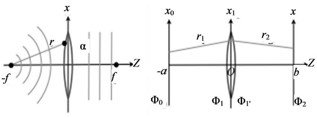
Figure 4. Left panel: wave front modification by a convex lens. Right panel: one lens image formation system.

where  is the aperture function of the lens defined by
  for
for  and
and  for
for .
.  represents a radius of the lens. With the assumption
 , the amplitude of the wave on the
  plane behind the lens is
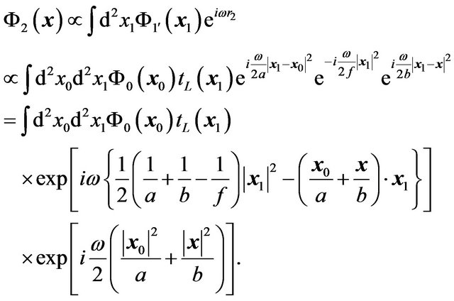 (23)
(23)
For a value of  satisfying the following relation (the lens equation for a convex thin lens),
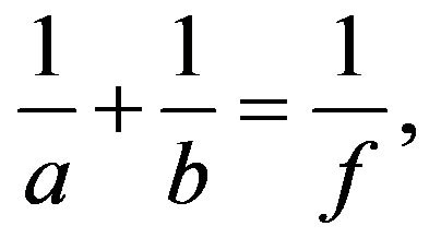 (24)
(24)
the wave amplitude becomes
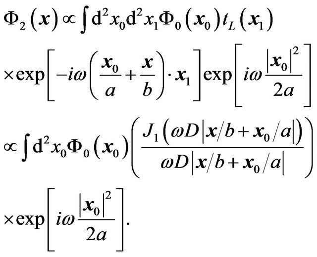 (25)
(25)
For 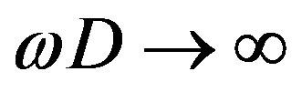 limit, the Bessel function in (25) becomes the delta function and we obtains the following wave amplitude on
 :
:
 (26)
(26)
Thus, a magnified image of the source field appears on the  plane. This reproduces the result of image formation in geometric optics; we have shown that an inverted images with magnification
  of a source object appears on
  satisfying the lens Equation (24).
If we do not take  limit, due to the diffraction effect, an image of a point source has finite size on the image plane called the Airy disk [8]. Its size is given by
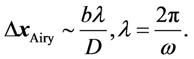 (27)
(27)
This value determines the resolving power of image formation system. For two point sources at  , their separation on the image plane is
 . To resolve them, their separation must be larger than the size of the Airy disk:
 (28)
(28)
The lefthand side of this inequality is the angular separation of the sources and  determines the resolving power of the image formation system.
3.2. Image Formation in Gravitational Lens System
As we have observed that a convex lens can be a device for image formation in wave optics, we combine it with a gravitational lensing system and obtain images by gravitational lensing. We consider a configuration of the gravitational lens system shown in Figure 5 and examine how the images of the source object appear using wave optics. As the source object, we assume a point source of wave. The amplitude of the wave just in front of a convex lens is
 (29)
(29)
This equation is the same as (7). After passing through the convex lens, the wave amplitude on the image plane  is given by
 (30)
(30)
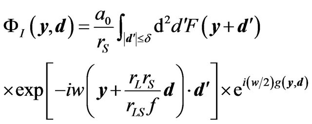
where  denotes the aperture of the convex lens. Using dimensionless variables, the wave amplitude on the image plane is
 (31)
(31)
If we choose the location of the image plane $z_2$ to satisfy the following “lens equation” for a convex lens,
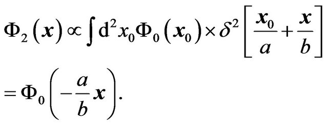
then the wave amplitude on the image plane becomes
 (32)
(32)
where . Thus the wave amplitude on the image plane is the Fourier transform of the amplification factor
  that gives the interference fringe pattern. Under the geometrical optics limit
 ,
,  integral in the amplification factor (13) can be approximated by the WKB form

where  is the solution of the lens equation
 (33)
(33)
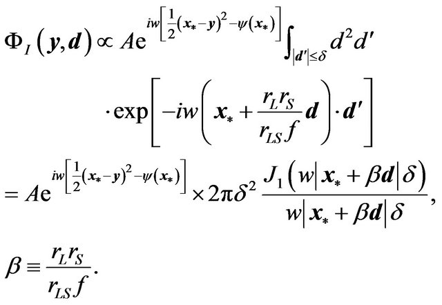
We have assumed that the aperture of the convex lens is sufficiently smaller than the size of the gravitational lensing system and  holds. Then, the wave amplitude on the image plane is
 (34)
(34)
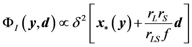
For  limit (large lens aperture limit or high frequency limit), we obtains
 (35)
(35)
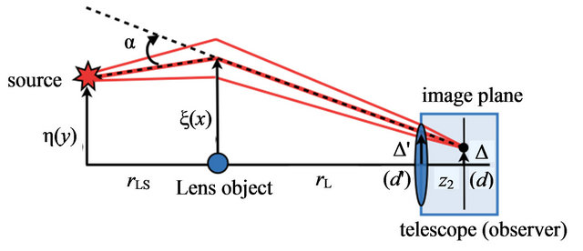
Figure 5. Configuration of a gravitational lens with a convex lens system. Orange lines represent paths that contribute to diffraction integrals.
and the image of the point source appears at the following location on the image plane determined by the lens Equation (33):
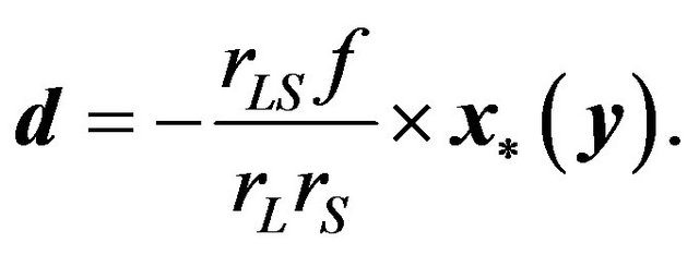 (36)
(36)
Equations (35) and (36) reproduce the same result of image formation in the geometrical optics (ray tracing) in terms of the wave optics. This is what we aim to clarify in this paper. If the lens Equation (33) has multiple solutions , the wave amplitude on the image plane becomes
 (37)
(37)
where  are constants.
As an example of image formation in a gravitational lensing system using wave optics, we present the wave optical images of a point source by the gravitational lensing of a point mass (Figure 6). They are obtained by Fourier transformation of the amplification factor  (Equation (32)) and the lens equation for gravitational lensing (15) has not been used. This procedure corresponds to image formation by a convex lens. These images correspond to images obtained by geometric optics (Figure 2). We can observe wave effect in these images.
In each image, we can observe concentric interference pattern which is caused by finite size of the lens aperture and this is not intrinsic feature of the gravitational lensing system. We can also observe radial non-concentric
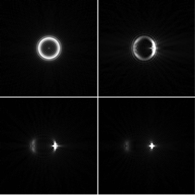
Figure 6. Wave optical images of a point source by the gravitational lensing of a point mass. Parameters are  (radius of the convex lens),
 .
.
patterns. They are caused by interference between double images and represent the intrinsic feature of the gravitational lensing system. For  case that corresponds to the Einstein ring in the geometrical optics limit, we can observe a bright spot at the center of the ring, which is the result of constructive interference and does not appear in geometric optics. For sufficiently large values of
 , the wave amplitude at the observer coincides with the result obtained by geometric optics. It is possible to estimate analytically the intensity distribution of the Einstein ring using the formula (20):
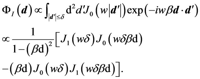 (38)
(38)
The intensity of the image  has a peak at
  (Figure 7) and this value exactly corresponds to the angular size of the Einstein ring
 (39)
(39)
4. Summary
We investigated image formation in gravitational lensing system based on wave optics. Instead of using the ray tracing method, we obtained images directly from wave functions at the observer without using the lens equation of gravitational lensing. For this purpose, we introduced a “telescope” with a single convex thin lens, which acts as a Fourier transformer for waves at the observer. The analysis in this paper relates the wave amplitude and images of the gravitational lensing directly. In the geometric optics limit of waves, images by lensing systems are
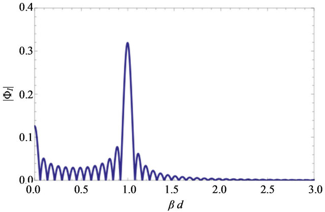
Figure 7.  for
for . The highest peak at
  corresponds to the Einstein ring. The peak at
  is the purely wave optical effect due to constructive interference of waves.
obtained by a lens equation that determines paths of each light rays. As light rays are trajectories of massless test particles (photon), expressing image in terms of wave is to express particle motion in terms of waves.
As an application and extension of analysis presented in this paper, we plan to investigate gravitational lensing by a black hole and obtain wave optical images of black holes. This subject is related to observation of black hole Shadows [5,6]. As the apparent angular sizes of black hole shadows are so small, the diffraction effect on images are crucial to resolve black hole shadows in observation using radio interferometer. For SgrA*, which is the black hole candidate at Galactic center, the apparent angular size of its shadow is estimated to be  arc seconds and this value is the largest among black hole candidates. For a sub-mm VLBI with a baseline length
 , using Equation (28), the condition to resolve the shadow becomes
  and this requirement shows the possibility to detect the black hole shadow of SgrA* using the present day technology of VLBI telescope. Thus, analysis of black hole shadows based on wave optics is an important task to evaluate detectability of shadows and determination of black hole parameters via imaging of black holes.
The topic of wave optical image formation in black hole spacetimes belongs to a classical problem of wave scattering in black hole spacetimes [9]. As is well known, waves incident to a rotating black hole are amplified by the superradiance [10] due to dragging of spacetimes. This effect enables waves to extract the rotation energy of black holes. On the other hand, it is known that particles can also extract the rotation energy of black holes via so called Penrose process. By investigating images of scattered waves by a rotating black hole, we expect to find out new aspect or interpretation of phenomena associated with superradiance in connection with the Penrose process.
5. Acknowledgements
This work was supported in part by the JSPS Grantin-Aid for Scientific Research (C) (23540297). The author thanks all member of “Black Hole Horizon Project Meeting” in which the preliminary version of this paper was presented.
REFERENCES
- P. Schneider, J. Ehlers and E. E. Falco, “Gravitational Lenses,” Springer-Verlag, New York, 1992. doi:10.1007/978-1-4612-2756-4
- T. T. Nakamura and S. Deguchi, “Wave Optics in Gravitational Lensing,” Progress of Theoretical Physics, Vol. 133, 1999, pp.137-153.
- C. Baraldo and A. Hosoya, “Gravitationally Induced Interference of Gravitational Waves by a Rotating Massive Object,” Physical Review D, Vol. 59, No. 8, 1999, Article ID: 083001.
- N. Matsunaga and K. Yamamoto, “The Finite Source Size Effect and Wave Optics in Gravitational Lensing,” JCAP, Vol. 01, 2006, p. 023.
- H. Falcke, F. Melia and E. Agol, “Viewing the Shadow of the Black Hole at the Galactic Center,” Astrophysical Journal, Vol. 528, 2000, pp. L13-L16.
- M. Miyoshi, K. Ishituska, S. Kameno and Z.-Q. Shen, “Direct Imaging of the Black Hole, SgrA*,” Progress of Theoretical Physics, Vol. 155, 2004, pp. 186-189.
- E. Herlt and H. Stephani, “Wave Optics of the Spherical Gravitational Lens Part I: Diffraction of a Plane Electromagnetic Wave by a Large Star,” International Journal of Theoretical Physics, Vol. 15, 1976, pp. 45-65.
- K. K. Sharma, “Optics: Principles and Applications,” Academic Press, Cambridge, 2006.
- J. A. H. Futterman, F. A. Handler, and R. A. Matzner, “Scattering from Black Holes,” Cambridge University Press, Cambridge, 1988. doi:10.1017/CBO9780511735615
- V. P. Frolov and I. D. Novikov, “Black Hole Physics,” Kluwer Academic Publishers, 1998. doi:10.1007/978-94-011-5139-9