Advances in Chemical Engineering and Science
Vol.3 No.4(2013), Article ID:37613,11 pages DOI:10.4236/aces.2013.34027
Interaction of Bubbles with Vortex Ring Launched into Bubble Plume
1EcoTopia Science Institute, Nagoya University, Nagoya, Japan
2Bridgestone Cycle, Ageo, Japan
Email: uchiyama@is.nagoya-u.ac.jp, sou.kusamichi@gmail.com
Copyright © 2013 Tomomi Uchiyama, Sou Kusamichi. This is an open access article distributed under the Creative Commons Attribution License, which permits unrestricted use, distribution, and reproduction in any medium, provided the original work is properly cited.
Received April 26, 2013; revised May 26, 2013; accepted June 16, 2013
Keywords: Vortex Ring; Bubble Plume; Bubble Entrainment; Vorticity; Visualization; PIV
ABSTRACT
This study is concerned with an experimental exploration for the interactions of bubbles with a vortex ring launched vertically upward into a bubble plume. A vortex ring launcher, composed of a cylinder and a piston, is mounted at the bottom of a water tank. Small hydrogen bubbles are released into still water from a cathode, which is wound around the cylinder outlet, by the electrolysis of water. The bubbles rise by the buoyant force and induce a bubble plume. The water in the cylinder is discharged into the bubble plume by the piston, resulting in a laminar vortex ring convecting along the central axis of the plume. Just after the launch of the vortex ring, the bubbles are spirally entrained into the vortex ring with the roll up of the shear layer. The void fraction within the vortex ring increases with the convection of the vortex ring until a certain displacement of the vortex ring, where the reduction occurs. The vortex ring convects with a constant velocity higher than that in still water. The entrained bubbles reduce the strength of the vortex ring.
1. Introduction
Gas bubbles released into a liquid induce the liquid flow as they rise due to the buoyant force. Such bubble-driven flow or bubble plume can attain the active contact and mixing between the gas and liquid phases. Therefore, it is utilized in engineering devices handling chemical reaction, bio-process, and coal liquefaction. It is also employed in environmental applications for ice prevention in lakes and purification of water. A number of researches have thus far been performed on bubble plumes. Various methods to predict the entrained liquid flow rate [1,2] and the plume characteristics [3,4] have been proposed. The relation between the meandering motion of rising bubble and the bubble flow rate has also been investigated [5]. The authors [6] carried out a numerical simulation for a plane bubble plume, and they analyzed the large-scale vortical structures as well as the bubble meandering motion. To heighten the performance and efficiency of the devices utilizing bubble plumes, it is effective to increase the interfacial area concentration of the plume. But there are few attempts at such increment.
In single-phase mixing layer, it is well known that the mixing and momentum transport of the fluid is dominated by the large-scale organized eddies. Rightley and Lasheras [7] performed an experimental study on a water mixing layer laden with small air bubbles, and elucidated that the bubble distribution is chiefly governed by the large-scale eddies. Druzhinin and Elghobashi [8] and Yang et al. [9] conducted numerical investigations on bubble-laden mixing layers, and reported that the bubbles concentrate preferentially around the center of largescale eddy. In single-phase jet, there are also organized large-scale eddies near the nozzle outlet. Milenkovic et al. [10,11] carried out experiments on a bubble-laden jet to study the bubble entrainment into the large-scale eddies generated by disturbances near the nozzle.
Vortex ring can transport mass and momentum through its convection with the self-induced velocity. The transport ability is so high that it has received much attention, and some attempts at applying a vortex ring to transport particles are reported. Domon et al. [12] performed an experimental study on the transport of solid particles in water. A vortex ring was loaded with small resin particles at the launch into still water, and the behavior of the particles convected with the vortex ring was observed. Yanagida et al. [13] proposed an olfactory display method for a virtual reality of the next generation. Scented particles, charged into a vortex ring, were efficiently delivered to a specific user’s nose by the convection of the vortex ring through the air. Yagami and Uchiyama [14] numerically simulated the convection of glass particles by a vortex ring in the air, and demonstrated that the particles are successfully transported when their Stokes number is small. Uchiyama [15] conducted a numerical simulation of a water jet laden with small air bubbles, and made clear that a vortex ring induced near the nozzle outlet by an axisymmetric disturbance involves the bubbles and convects with the bubbles. The abovementioned results suggest that a vortex ring is usefully employed for the control of bubble motion. Therefore, a vortex ring launched into a bubble plume may increase the interfacial area concentration. As a vortex ring convects with inducing the liquid flow, it may also enhance the mixing between the two phases. But there are few researches on a vortex ring laden with bubbles. Sridhar and Katz [16] investigated experimentally the motion of a bubble entrained into a vortex ring, and showed that the motion calculated by the measured lift and drag forces agrees well with the experimentally visualized result. Sridhar and Katz [17] also studied the effect of entrained bubbles on the strength and vortical structure of a vortex ring, and made clear that the deformation of the vortex ring occurs even when a few bubbles are entrained. These experimental studies did not examine the changes of dimension and convection velocity of vortex ring caused by the bubble. The number of bubbles was so small, and the bubble volume fraction within the vortex ring was not measured. Consequently, the interactions between a vortex ring and the entrained bubbles are not fully clarified.
The objective of this study is to explore experimentally the interactions of bubbles with a vortex ring launched vertically upward into an annular bubble plume. A vortex ring launcher, composed of a cylinder and a piston, is mounted at the bottom of a water tank. Small hydrogen bubbles are released into still water from a cathode, which is wound around the cylinder outlet, by the electrolysis of water. The bubbles rise by the buoyant force and induce a bubble plume. The water in the cylinder is discharged into the bubble plume by the piston, resulting in a vortex ring convecting vertically upward in the plume. In this study, a laminar vortex ring is launched into a bubble plume. The mean bubble diameter is 0.2 mm, and the bubble flow rate is 4.1 mm3/s. The behavior of the vortex ring and the bubble motion are investigated in a region, of which vertical height from the cylinder outlet is six times the inner diameter of the cylinder.
2. Experimental Set-Up and Method
2.1. Experimental Set-Up
Figure 1 outlines the experimental set-up. The experiment is conducted in a water tank made of transparent acrylic resin. The width and depth of the tank are 300 mm, while the height is 1000 mm. The top of the tank is open to the atmosphere. A vortex ring launcher, composed of a cylinder and a piston, is mounted at the bottom of the tank. The cylinder centerline is parallel to the vertical direction. A cathode is wound around the cylinder outlet, and an anode is placed on the tank wall. Applying a DC voltage between the electrodes, small hydrogen bubbles are released from the cathode. The bubbles rise by the buoyant force and induce the water flow around them, resulting in an annular bubble plume.
A vortex ring is launched vertically upward into the bubble plume by discharging the water in the cylinder with the piston. The push of the piston is performed with a slider connected to an AC servomotor. The velocity and stroke are controlled with a personal computer.
The vortex ring and the bubbles are visualized by a laser light sheet, of which power, wavelength and thickness are 100 mW, 532 nm and 1 mm, respectively. Their images in the vertical plane passing through the cylinder centerline are captured by a video camera. The spatial resolution, the frame rate and the shutter speed are 640 × 480 pixels, 200 fps and 1/200 s, respectively.
The water and bubble velocities are measured by using a PIV system. Nylon particles (mean diameter: 80 μm, specific weight: 1.02) are laden as the tracer for the water flow. Therefore, the bubbles should be removed from the visualized images when measuring the water velocity. In this experiment, the remove was properly performed by
Figure 1. Experimental set-up.
setting the camera aperture at an appropriate level, be cause the brightness of the bubble differs greatly from that of the tracer particle.
2.2. Launch of Vortex Ring
Figure 2 shows the close up for the vortex ring launcher mounted at the bottom of the water tank. The water depth is 300 mm. The piston stroke L0 is 100 mm, and the top dead center is 46 mm below the cylinder outlet. The inner diameter of cylinder D0 is 42.5 mm, while the outer one is 57.8 mm. The height of cylinder outlet from the tank bottom is 45 mm. The origin of the vertical (z) and radial (r) axes is set at the center of cylinder outlet.
Figure 3 presents the time variation for the piston motion, where the displacement zp and the velocity U0 (= dzp/dt) are plotted. The motion time T0 is 0.748s. The velocity profile is trapezoid, and the maximum velocity Um (=154 mm/s) is maintained for 0.64T0.
When a fluid is discharged from a cylinder into the still fluid by a piston, a laminar vortex ring or a turbulent one is launched depending on the condition for the discharge. Glezer [18] identified the conditions that lead to the generation of the laminar and turbulent vortex rings as shown in Figure 4. The identification is based on the cylinder inner diameter D0, the piston stroke L0 and the circulation of vortex ring Γ0. Γ0 is computed by the following equation:
Figure 2. Vortex ring launcher and water tank.
Figure 3. Displacement and velocity profiles of piston.
Figure 4. Condition for launch of vortex ring.
 (1)
(1)
where T0 and U0 are the motion time and velocity of the piston respectively.
The circulation Γ0 calculated from Equation (1) results in Γ0/ν = 7252. According to the identification of Glezer in Figure 4, it is found that a laminar vortex ring is launched into still water in this experiment.
2.3. Launch of Vortex Ring
Small hydrogen bubbles are released by the electrolysis of water. A copper wire of diameter 0.1 mm is employed for the cathode. It is wound around the cylinder of the vortex ring launcher, as illustrated in Figure 2. The height is 5 mm below the cylinder outlet.
The hydrogen bubbles released from the circular cathode are spherical, and their diameter is less than 0.5 mm. The voltage between the electrodes varies the amount of the bubbles released per unit time. This study sets the voltage at 60 V. The bubble volume release rate, measured by downward displacement of water, is 4.1 mm3/s, while the bubble mean diameter is 0.2 mm.
When the terminal velocity vt for a single bubble with diameter 0.2 mm rising in still water is estimated from the numerical calculation, it is 16.3 mm/s.
3. Experimental Results and Discussions
3.1. Behavior of Vortex Ring Launched into Still Water
First, the behavior of the vortex ring in still water is investigated to examine the characteristics of the vortex ring in this experimental set-up. A visualized image for the central vertical cross-section of the vortex ring is presented in Figure 5. It is acquired by adding water paint to the launched water in the cylinder. The mean diameter and volume fraction of the paint are about 50 μm and 0.006 respectively. A vortex pattern is clearly observed. A shear layer originates at the boundary between the water discharged from the cylinder and the still water in the tank, and the paint is entrained into the vortex core with the roll up of the shear layer. A laminar distribution of the paint is found behind the vortex ring. There are no active mixings. The visualized image indicates the characteristics of a laminar vortex ring. This is parallel to the Glezer’s identification [18] demonstrated in Figure 4.
On the visualized image of the central vertical crosssection of the vortex ring shown in Figure 5, the z coordinate of the center for vortex core is regarded as the displacement of vortex ring zv, while the distance between the centers of the vortex cores is defined as the diameter of vortex ring D.
The displacement of vortex ring zv changes with the

Figure 5. Visualized image of vortex ring launched into still water.
lapse of time as shown in Figure 6, where the piston maximum velocity Um and the cylinder inner diameter D0 are used for the nondimensional expressions. The time when the piston reaches the top dead center is set at t = 0. The change of zv is almost linear, indicating that the vortex ring rises with a constant velocity in still water. The rising velocity, dzv/dt, is 0.41 Um. The rise almost ceases at zv/D0 ≒ 5.8. Because the vortex ring is affected by the water surface at z/D0 = 6.
The change in the diameter D is plotted against the displacement zv in Figure 7. The diameter remains almost unaltered at zv/D0 ≦ 5.8. The marked increment at zv/D0 > 5.8 is attributable to the effect of the water surface.
This study measures the water velocity distribution on the vertical central cross-section of the vortex ring at four displacements of zv/D0 = 0.78, 2.77, 4.1, 5.01, as mentioned later. The measurement section includes the vortex core. The radial and vertical widths are 2.23D0 and 1.59D0 respectively. When the vorticity is calculated at each displacement, the circulation Γ can be estimated from the distribution. The nondimensional circulation Γ/ν is plotted by the open symbols in Figure 8. The circulation remains almost unaltered in the region investigated by this study. When the piston reaches the top dead
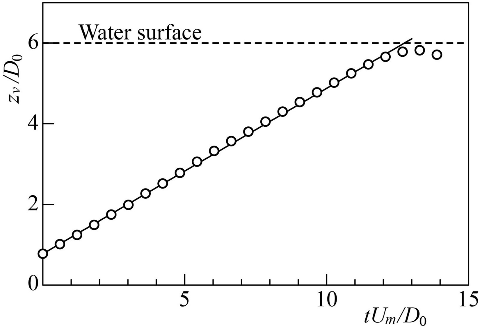
Figure 6. Time variation for displacement of vortex ring in still water.
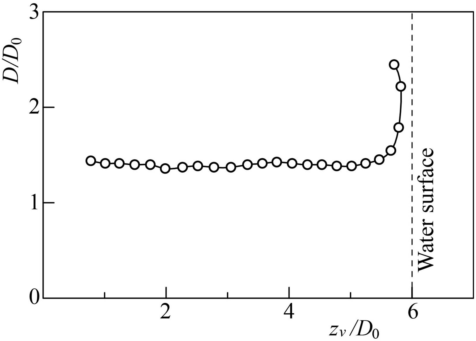
Figure 7. Axial evolution for diameter of vortex ring in still water.

Figure 8. Axial change in circulation around vortex core.
center (t = 0), the displacement zv/D0 is 0.78. The circulation Γ/ν at this displacement is 8063. It is slightly larger than the value, Γ/ν = 7252, estimated from Equation (1). Similar result was also reported by Glezer [18] and Gharib et al. [19]. Equation (1) is based on a slug model assuming that the water velocity is uniform within the cylinder cross-section. The difference from the measurement is attributable to this assumption.
3.2. Characteristics of Bubble Plume
Figure 9 illustrates the bubble distribution for the temporally developed bubble plume, where the distribution on the vertical plane passing through the plume centerline is depicted. The bubbles, generated from the cathode wound around the cylinder outlet, rise due to the buoyant force. They hardly move straight in the vertical direction. They shift toward the plume centerline near the cathode (z/D0 ≦ 1), and meander slightly with their rise at z/D0 > 1. The shift is caused by the fact that the water outside of the plume flows toward the centerline to satisfy the mass conservation low of the water. Because the rising bubbles induce an upward water flow around the centerline.
When the time-averaged water velocity ![]() is measured, the axial (vertical) component
is measured, the axial (vertical) component  changes in the radial direction as plotted in Figure 10, where the distributions at four elevations from the cylinder outlet are presented. At z/D0 = 0.78,
  takes its maximum value at r/D0 = 0.26. This is because the bubbles released from the cylinder tip shift toward the centerline and they concentrate at this radial position as seen in Figure 9, and accordingly an upward water flow with higher vertical velocity is induced there. At z/D0 = 2.77 and 4.1,
  reaches the maximum on the centerline of the plume. The velocity
  increases with the elevation z. One can confirm the entrainment of the water into the plume. A spatially developing buoyant jet occurs. The velocity lowers at z/D0 = 5.01 owing to the effect of the water surface.
The time-averaged bubble velocity  is measured at the radial positions of r/D0 =
 ![]() 0.25. It changes in the vertical (z) direction as shown in Figure 11, where the
0.25. It changes in the vertical (z) direction as shown in Figure 11, where the

Figure 9. Visualized image of bubbles in bubble plume without vortex ring.
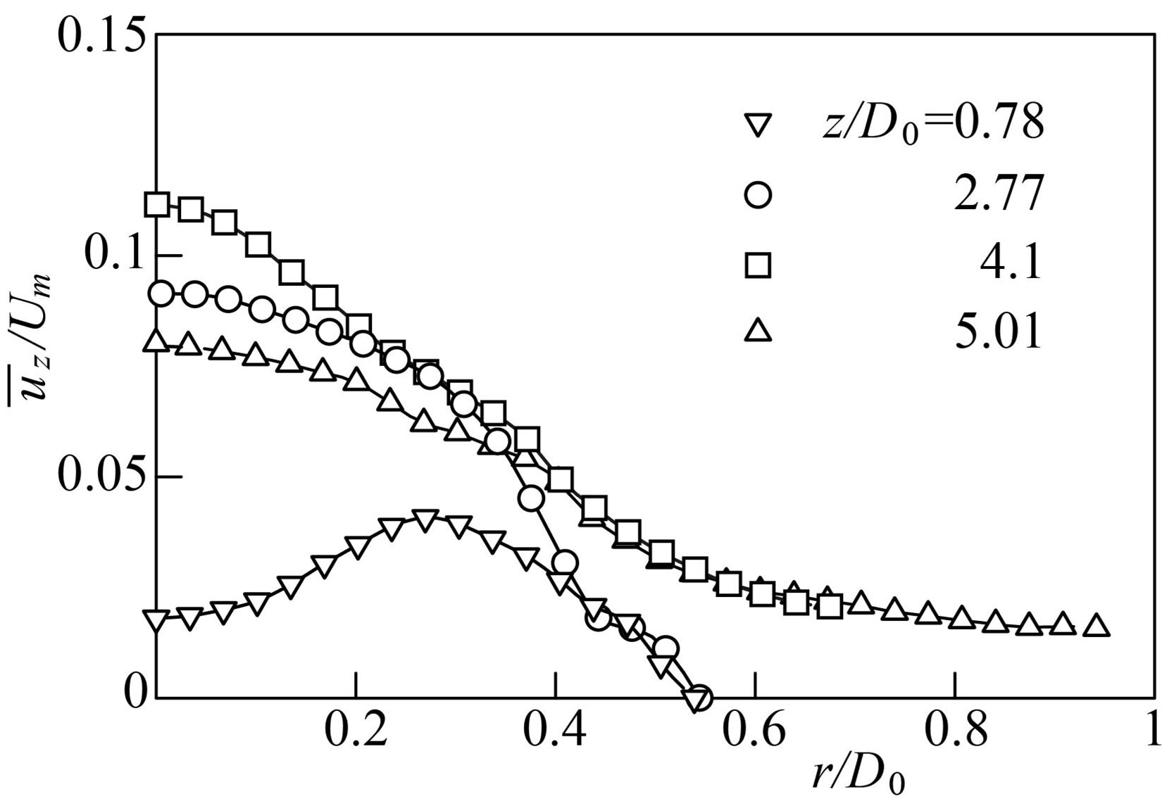
Figure 10. Time-averaged water velocity in bubble plume without vortex ring.
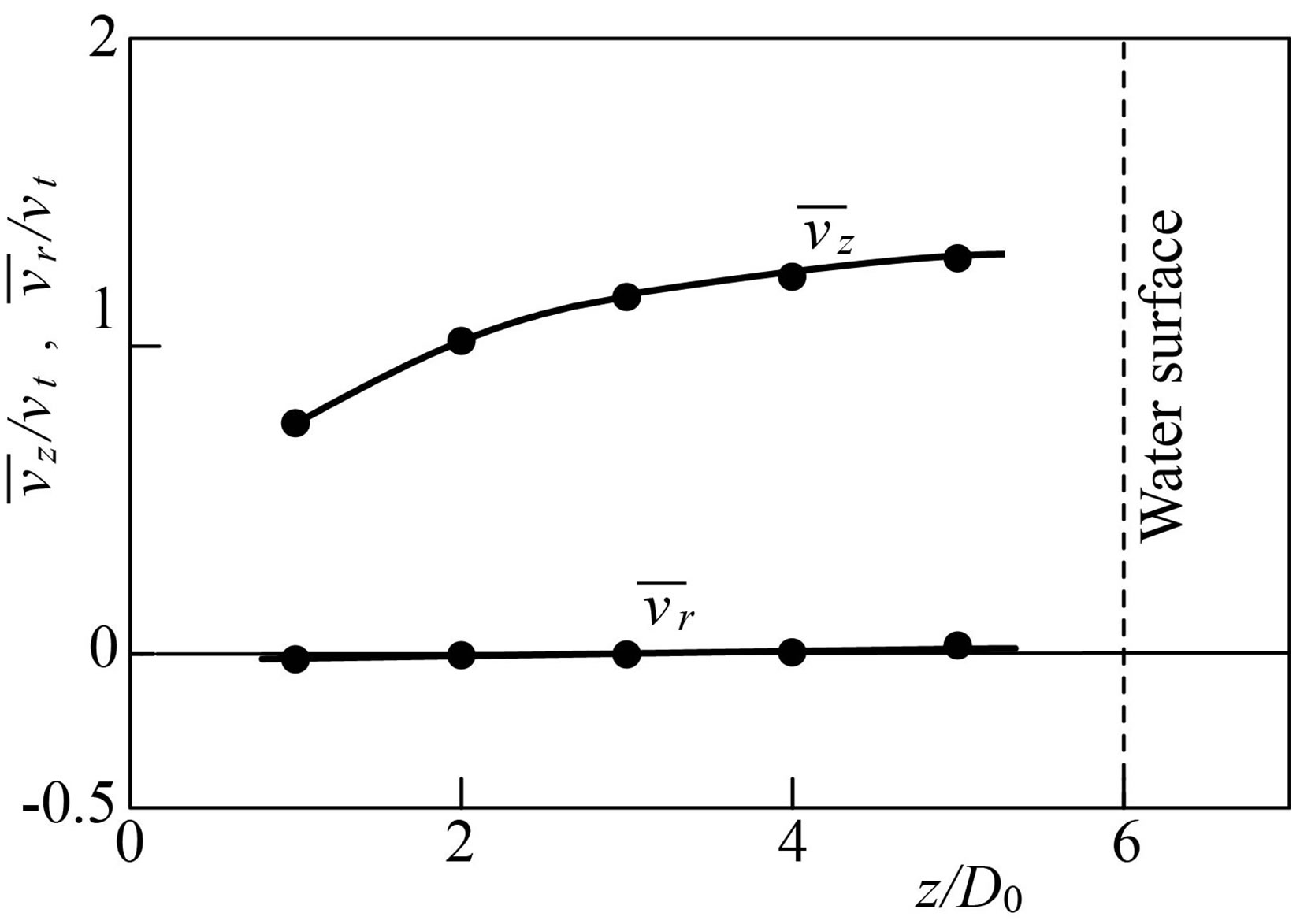
Figure 11. Time-averaged bubble velocity in bubble plume at r/D0 = ±0.25.
bubble terminal velocity vt is used for the nondimensional expression. The radial positions correspond to the regions where the bubbles concentrate as seen in Figure 9. The axial (vertical) velocity  heightens with increasing the elevation, demonstrating that the plume is spatially developing in the measured region. But it shows a tendency to be saturated. The velocity
  is higher than the bubble terminal velocity at z/D0 ≧ 2. This is owing to the fact that the bubbles rise relative to the vertically upward water flow induced by them. The radial (horizontal) velocity
  is much lower than
 , and the change in the vertical direction is small.
3.3. Behavior of Vortex Ring Launched into Bubble Plume and Bubble Distribution
When the vortex ring is vertically launched into the bubble plume along the centerline, the bubbles distribute as shown in Figure 12. The distributions on the central vertical cross-section at four displacements of vortex ring zv are presented. At zv/D0 = 0.78, the bubbles above the vortex ring tend to move to the rear of the vortex ring

Figure 12. Visualized image of bubbles around vortex ring launched into bubble plume.
along the vortex core, and they are being spirally entrained into the vortex core. The bubble entrainment is caused by the roll up of the shear layer originating from the cylinder tip. This displacement is at the time tUm/D0 = 0 when the piston reaches the top dead center. At zv/D0 = 2.77, the spiral entrainment further proceeds. The bubble volume fraction within the cross-section reaches its maximum value at this displacement as mentioned later. At zv/D0 = 4.1, the number of bubbles in the vortex ring around the center axis (r/D0 = 0) is smaller than that at zv/D0 = 2.77, and a lot of bubbles distribute behind the vortex ring. Because the bubbles moving to the rear of vortex ring are hardly entrained into the vortex ring due to the cease of the roll up for the shear layer, and accordingly they are left behind the vortex ring. When the vortex ring rises more (zv/D0 = 5.01), the amount of bubbles inside the vortex ring increases again due to the collision between the vortex ring and the bubbles accumulated near the water surface. A marked increment occurs around the center axis.
On the visualized image of the bubble distribution within the central vertical cross-section of the vortex ring, the z coordinate of the center for vortex core is regarded as the displacement zv, while the distance between the centers of the vortex cores is defined as the diameter D. Figure 13 indicates the image at zv/D0 = 1.22. It is confirmed that zv and D are clearly identified.
Figure 14 shows the time variation for zv. The displacement in the bubble plume is almost the same as that in still water at tUm/D0 ≦ 2.42. But it is larger at tUm/D0 > 2.42, indicating that the rising velocity of the vortex ring in the bubble plume is higher. Because the vortex ring is affected with the vertically upward water flow induced by the rising bubbles as explained later. When tUm/D0 > 2.42, the time variation of zv is linear. The vortex ring rises at a constant velocity.

Figure 13. Displacement and diameter of vortex ring launched into bubble plume.
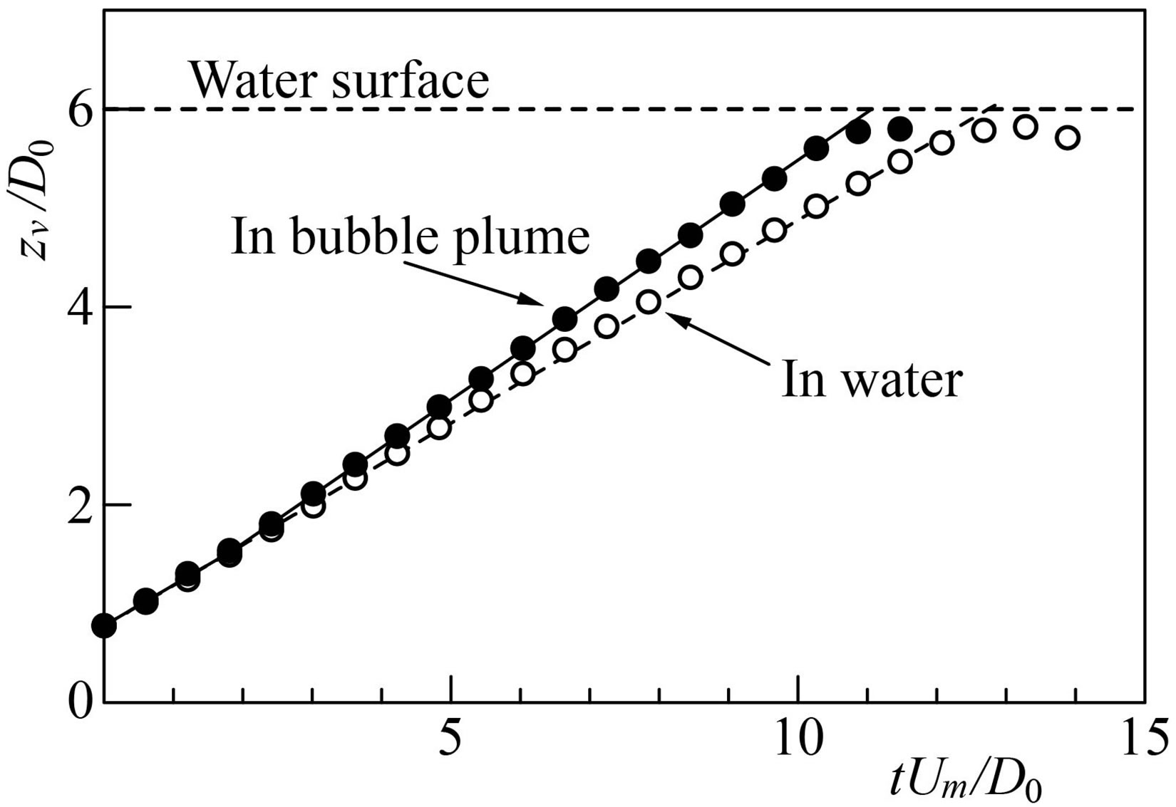
Figure 14. Time variation for displacement of vortex ring launched into bubble plume.
The diameter of vortex ring D changes as a function of zv as presented in Figure 15. The diameter D in the bubble plume decreases with the rise of vortex ring. Thus, the diameter is smaller than that in still water. A buoyant jet is generated as shown in Figure 9, and there exists an upward water flow around the centerline (r/D0 = 0). Therefore, the water is entrained into the bubble plume, and the water flowing toward the centerline reduces the D value.
3.4. Void Fraction in Central Vertical Cross-Section of Vortex Ring
To grasp the change in the amount of bubbles inside the vortex ring with the convection of the vortex ring, the void fraction α in a rectangular region surrounding the vortex core is calculated. Binarized images for the bubble distribution are used for the calculation. The region is depicted in Figure 13. The width and the height are 1.25D0, and the centroid is fixed at the center of the vortex core.
Figure 16 shows the relation between the void fraction and the displacement of vortex ring zv. At 0.78 ≦ zv/D0 ≦ 2.77, α increases monotonically. This is because the bubbles are being spirally entrained into the vortex ring with the roll up of the velocity shear layer, as seen in Figures 12(a) and (b). But α decreases at 2.77 ≦ zv/D0 ≦ 4.1 where the strength of the shear layer lessens. Because the bubbles are left behind the vortex ring, as seen in Figure 12(c). At zv/D0 > 4.1, α increases again (Figure 12(d)). This is attributable to the fact that the vortex ring collides with the bubbles accumulated near the water surface. The maximum value of α at zv/D0 = 2.77 is 2.43 times as large as that near the cylinder outlet (zv/D0 = 0.78).
3.5. Distributions for Velocity and Vorticity of Water
The distribution of water velocity on the central vertical cross-section of the vortex ring is shown in Figure 17,
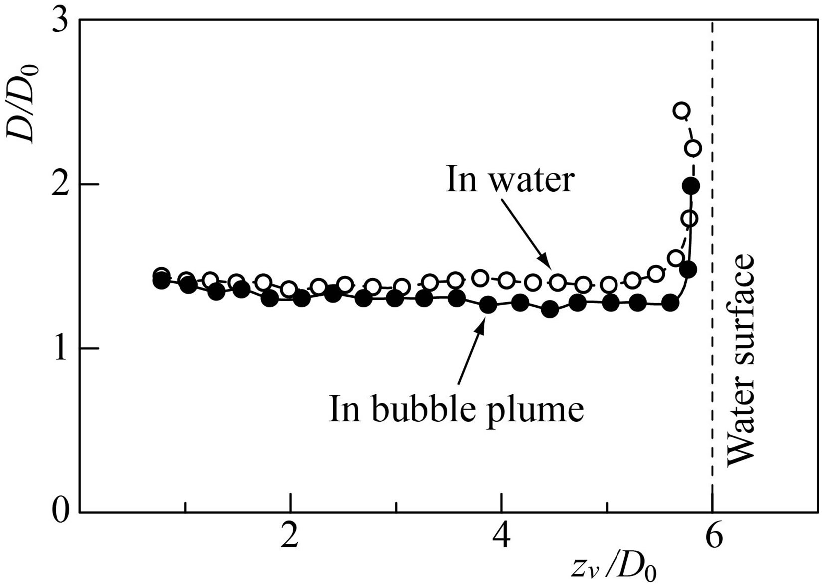
Figure 15. Axial evolution for diameter of vortex ring launched into bubble plume.
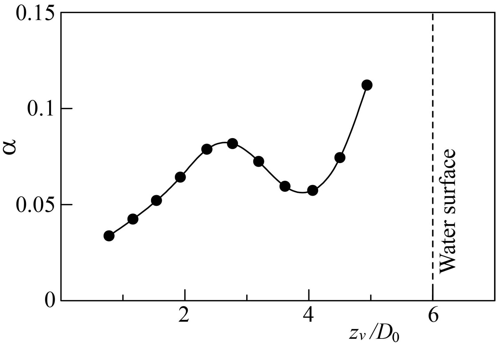
Figure 16. Axial evolution for void fraction in cross-section of vortex ring.
where the ensemble-averaged velocity  at four displacements of vortex ring is presented. The distribution in still water and that in the bubble plume are compared, and the bubble distribution is also presented. When the vortex ring is launched into still water, the vortex core remains nearly circular. The water velocity scarcely depends on the displacement of the vortex ring. Even when the vortex ring is launched into the bubble plume, the vortex core exists. The vortex core at zv/D0 = 0.78 and 2.77 is not circular, but deforms with the convection of vortex ring. The deformation is reconfirmed from the contour lines for the magnitude of velocity shown in Figure 18. The deformation is mainly caused by the shear flow of water induced by the rising bubbles. It may also be attributable to the fact that the time variation of the bubble distribution around the vortex core changes markedly due to the active bubble entrainment. Sridhar and Katz [17] made clear that a vortex ring deforms even when a few bubbles are entrained. The present authors elucidate the variation of the water velocity in the vortex core with the convection of vortex ring. They also grasp the change of the shape for vortex core.
Figure 19 presents the axial (vertical) component of the ensemble-averaged water velocity , where the distribution on the horizontal line passing through the
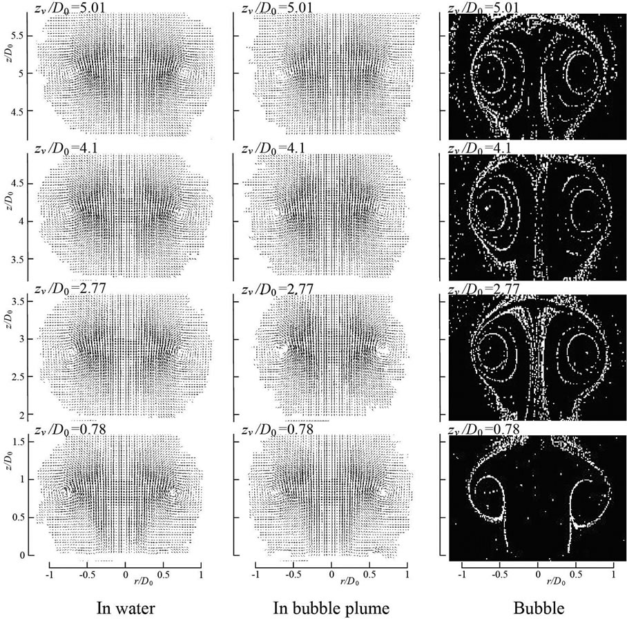
Figure 17. Water velocity around vortex ring.

Figure 18. Contour lines for magnitude of water velocity around vortex core.
centers of the vortex cores shown in Figure 17 is plotted. The velocity remains unaltered between the vortex cores. The velocity  in the bubble plume is higher than that in still water at zv/D0 = 2.77 and 4.1. This is due to the upward water flow of the plume. The velocity gradient around the center of the vortex core in the bubble plume is smaller than that in still water.
The distribution for the ensemble-averaged vorticity  on the central vertical cross-section of vortex ring is shown in Figure 20, where the bubbles are superimposed on the result in the bubble plume. The absolute value of the vorticity around the vortex core in the bubble plume is lower than that in still water at every displacement of the vortex ring. Because the friction acts on the interface between the bubbles and the water. Ruetsch and Meiburg [20] conducted a numerical simulation of a plane shear layer laden with bubbles. They highlighted that the bubbles concentrate around the vortex center and that the concentration reduces the strength of the vortex strength.
The present experiment grasps the variation in the vorticity distribution with the convection of vortex ring, and therefore it elucidates the dynamic interaction between the vortex ring and the entrained bubbles.
The circulation Γ around the vortex core in the bubble plume is calculated from the vorticity field. The nondi-
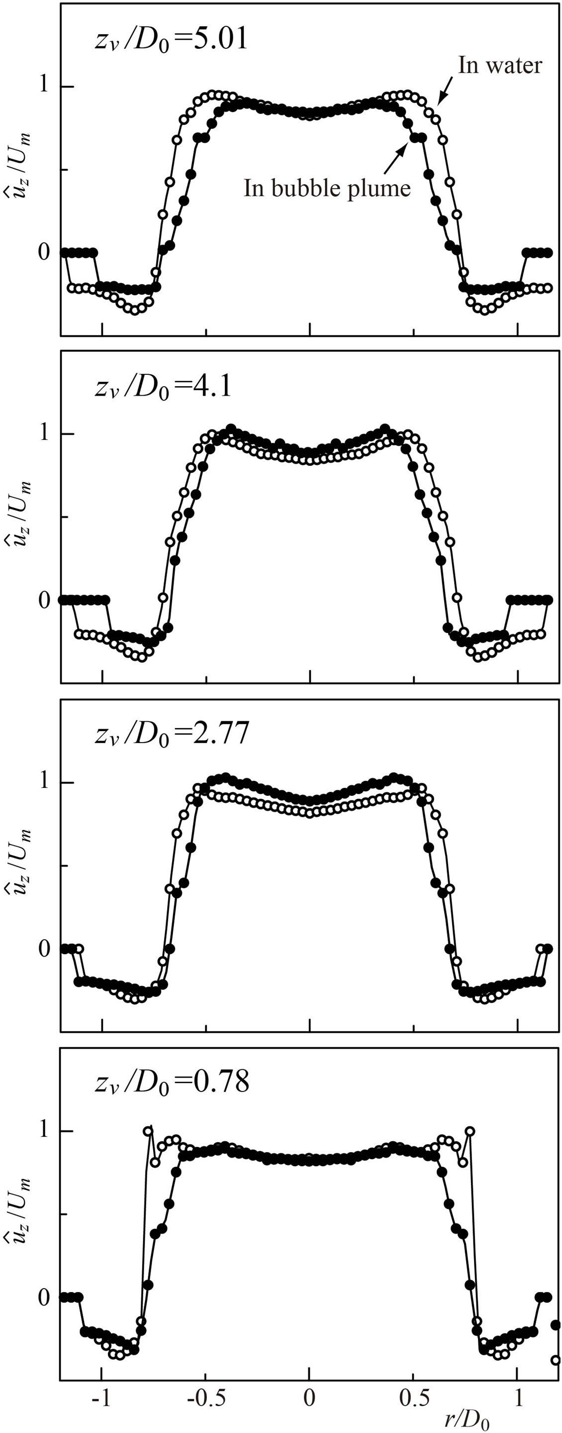
Figure 19. Water axial velocity on horizontal line passing through vortex cores.
mensional circulation Γ/ν is plotted by the painted symbols in Figure 8. At zv/D0 ≦ 4, the circulation in the bubble plume is higher than that in still water. Because the effect of the upward water flow is superimposed on Γ. The circulation in the bubble plume lessens with the rise of vortex ring. Because the absolute value of the vorticity in the vortex ring decreases owing to the friction between the water and the entrained bubbles.
The vorticity  on the horizontal line passing through the
centers of the vortex cores is plotted in Figure 21. At zv/D0 = 0.78, the maximum value for the vorticity in the water is markedly high. One can find the occurrence of a velocity shear layer from the cylinder tip. But the maximum value in the bubble plume at the displacement is not so high. This is attributable to the fact that the velocity gradient of the shear layer is reduced by the bubbles. The absolute value of  lessens greatly around the vortex core, indicating that the vorticity distribution is flattened by the entrained bubbles.
4. Conclusions
The interactions of bubbles with a vortex ring launched
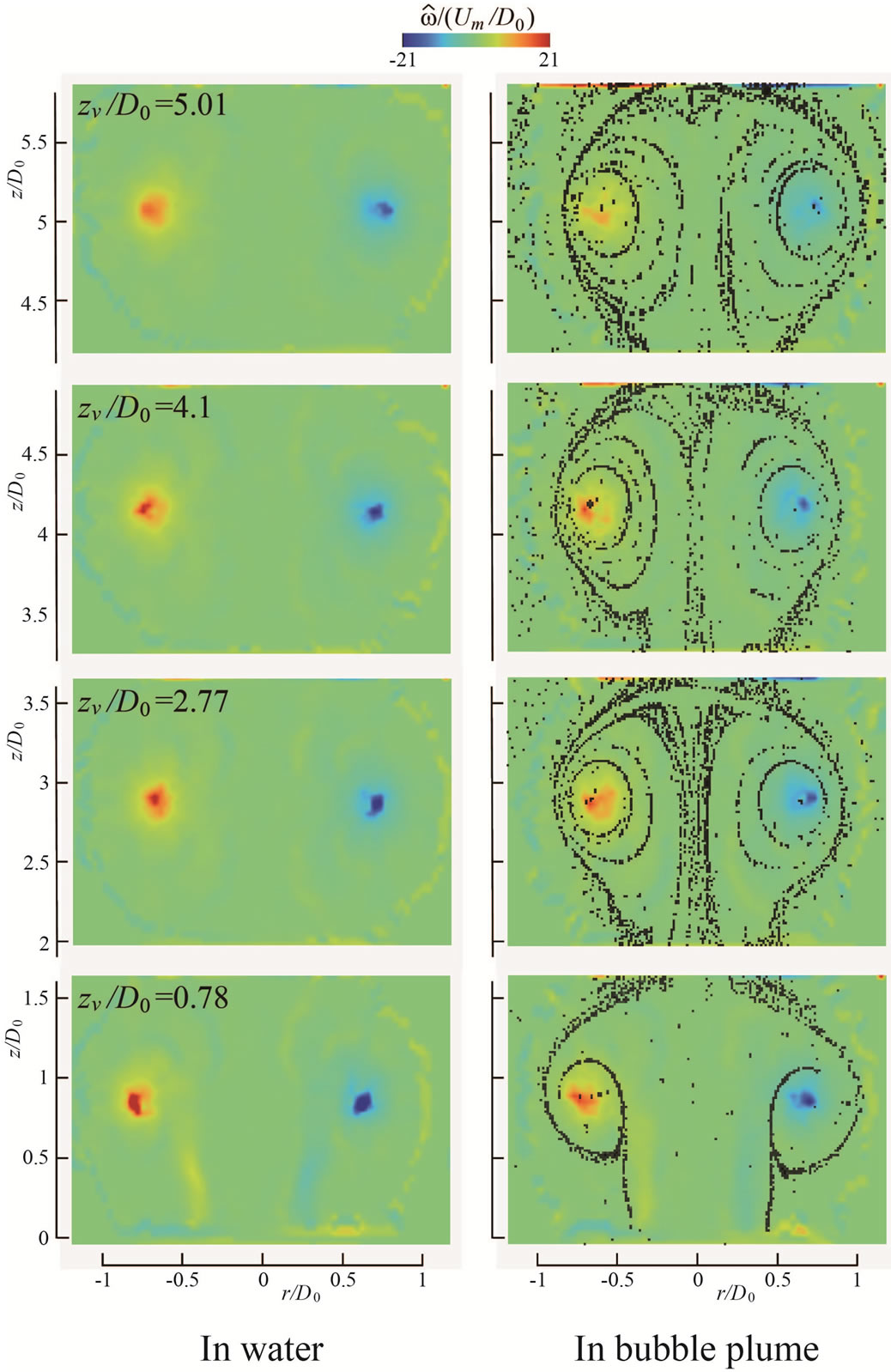
Figure 20. Vorticity distribution around vortex ring.
into a bubble plume were investigated. Laminar vortex ring was vertically launched into bubble plume. The mean bubble diameter is 0.2 mm. The results are summarized as follows:
1) The bubbles are spirally entrained into the vortex ring just after the launch of vortex ring. When the vortex ring reaches a certain height, the amount of the bubbles around the center axis of vortex ring lessens, and the bubbles moving to the rear of the vortex ring are left behind the vortex ring.
2) The rising velocity of vortex ring in the bubble plume is higher than that in still water. This is because the vortex ring is affected by the vertically upward water flow induced by the bubbles. The velocity of vortex ring is almost constant.
3) The diameter of vortex ring reduces with the rise of the vortex ring. The bubble plume is generated by the rising bubbles, and there exists the vertically upward water flow around the centerline. Therefore the water is entrained into the plume, and the water flowing toward the centerline reduces the diameter.
4) The void fraction in the central vertical cross-section of vortex ring increases until a certain displacement
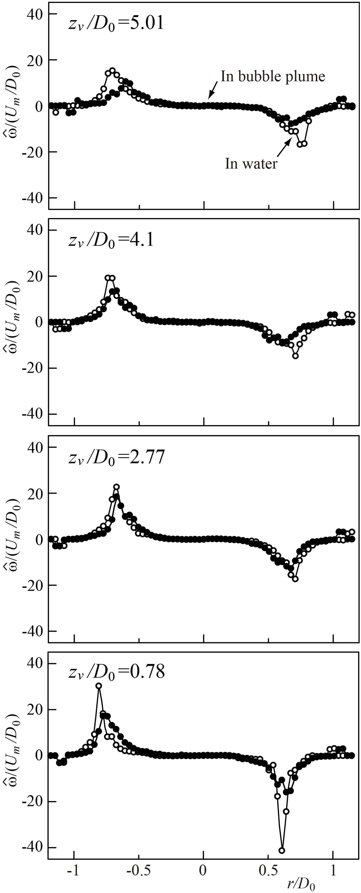
Figure 21. Vorticity on horizontal line passing through vortex cores.
of vortex ring, where the reduction occurs. It heightens again when the vortex ring approaches the water surface. Because the vortex ring collides with the bubbles accumulated near the water surface.
5) The vortex core deforms with the convection of vortex ring. The entrained bubbles cause the decrement of the absolute value for the vorticity around the vortex core, reducing the strength of vortex ring.
REFERENCES
- N. A. Hussain and R. Siegel, “Liquid Jet Pumped by Rising Gas Bubbles,” Journal of Fluids Engineering, Vol. 98, No. 1, 1976, pp. 49-57. http://dx.doi.org/10.1115/1.3448206
- A. M. Leitch and W. D. Baines, “Liquid Volume Flux in a Weak Bubble Plume,” Journal of Fluid Mechanics, Vol. 205, No. 1, 1989, pp. 77-98. http://dx.doi.org/10.1017/S0022112089001953
- J. H. Milgram, “Mean Flow in Round Bubble Plumes,” Journal of Fluid Mechanics, Vol. 133, No. 1, 1983, pp. 345-376. http://dx.doi.org/10.1017/S0022112083001950
- S. A. Socolofsky and E. E. Adams, “Role of Slip Velocity in the Behavior of Stratified Multiphase Plumes,” Journal of Hydraulic Engineering, Vol. 131, No. 4, 2005, pp. 273-282. http://dx.doi.org/10.1061/(ASCE)0733-9429(2005)131:4(273)
- M. Alam and V. H. Arakeri, “Observations on Transition in Plane Bubble Plumes,” Journal of Fluid Mechanics, Vol. 254, No. 1, 1993, pp. 363-374. http://dx.doi.org/10.1017/S0022112093002174
- T. Uchiyama and S. Matsumura, “Three-Dimensional Vortex Method for the Simulation of Bubbly Flow,” Journal of Fluids Engineering, Vol. 132, No. 10, 2010, pp. 1-8.
- P. M. Rightley and J. C. Lasheras, “Bubble Dispersion and Interphase Coupling in a Free-Shear Flow,” Journal of Fluid Mechanics, Vol. 412, No. 1, 2000, pp. 21-59. http://dx.doi.org/10.1017/S002211200000817X
- O. A. Druzhinin and S. E. Elghobashi, “Direct Numerical Simulation of a Three-Dimensional Spatially Developing Bubble-Laden Mixing Layer with Two-Way Coupling,” Journal of Fluid Mechanics, Vol. 429, 2001, pp. 23-61. http://dx.doi.org/10.1017/S002211200000817X
- X. Yang, N. H. Thomas, L. J. Guo and Y. Hou, “TwoWay Coupled Bubble Laden Mixing Layer,” Chemical Engineering Science, Vol. 57, No. 4, 2002, pp. 555-564. http://dx.doi.org/10.1016/S0009-2509(01)00416-X
- R. Z. Milenkovic, B. Sigg and G. Yadigaroglu, “Study of Periodically Excited Bubbly Jets by PIV and Double Optical Sensors,” International Journal of Heat and Fluid Flow, Vol. 26, No. 6, 2005, pp. 922-930. http://dx.doi.org/10.1016/j.ijheatfluidflow.2005.10.010
- R. Z. Milenkovic, B. Sigg and G. Yadigaroglu, “Bubble Clustering and Trapping in Large Vortices, Part 1: Triggered Bubbly Jets Investigated by Phase Averaging,” International Journal of Multiphase Flow, Vol. 33, No. 10, 2007, pp. 1088-1110. http://dx.doi.org/10.1016/j.ijmultiphaseflow.2007.05.003
- K. Domon, O. Ishihara and S. Watanabe, “Mass Transport by a Vortex Ring,” Journal of the Physical Society of Japan, Vol. 69, No. 1, 2000, pp. 120-123. http://dx.doi.org/10.1143/JPSJ.69.120
- Y. Yanagida, S. Kawato, H. Noma, A. Tomono and N. Tetsutani, “Projection-Based Olfactory Display with Nose Tracking,” Proceedings of IEEE Virtual Reality, 2004, Chicago, pp. 43-50.
- H. Yagami and T. Uchiyama, “Numerical Simulation for the Transport of Solid Particles with a Vortex Ring,” Advanced Powder Technology, Vol. 22, No. 1, 2011, pp. 115-123. http://dx.doi.org/10.1016/j.apt.2010.09.002
- T. Uchiyama, “Three-Dimensional Vortex Simulation of Bubble Dispersion in Excited Round Jet,” Chemical Engineering Science, Vol. 59, No. 7, 2004, pp. 1403-1413. http://dx.doi.org/10.1016/j.ces.2003.12.024
- G. Sridhar and J. Katz, “Drag and Lift Forces on Microscopic Bubbles Entrained by a Vortex,” Physics of Fluids, Vol. 7, No. 2, 1995, pp. 389-399. http://dx.doi.org/10.1063/1.868637
- G. Sridhar and J. Katz, “Effect of Entrained Bubbles on the Structure of Vortex Rings,” Journal of Fluid Mechanics, Vol. 397, 1999, pp. 171-202. http://dx.doi.org/10.1017/S0022112099006187
- A. Glezer, “The Formation of Vortex Rings,” Physics of Fluids, Vol. 31, No. 12, 1988, pp. 3532-3542. http://dx.doi.org/10.1063/1.866920
- M. Gharib, E. Rambod and K. Shariff, “A Universal Time Scale for Vortex Ring Formation,” Journal of Fluid Mechanics, Vol. 360, 1998, pp. 121-140. http://dx.doi.org/10.1017/S0022112097008410
- G. R. Ruetsch and E. Meiburg, “Two-Way Coupling in Shear Layers with Dilute Bubble Concentrations,” Physics of Fluids, Vol. 6, No. 8, 1994, pp. 2656-2670. http://dx.doi.org/10.1063/1.868155