Journal of Transportation Technologies
Vol. 3 No. 2A (2013) , Article ID: 31799 , 6 pages DOI:10.4236/jtts.2013.32A001
Coupled Vibration Analysis of Vehicle-Bridge System Based on Multi-Boby Dynamics
Bridge Engineering Department, Southwest Jiaotong University, Chengdu, China
Email: dsshan@163.com, shengai_cui@126.com, huang_zhen_@126.com
Copyright © 2013 Deshan Shan et al. This is an open access article distributed under the Creative Commons Attribution License, which permits unrestricted use, distribution, and reproduction in any medium, provided the original work is properly cited.
Received January 14, 2013; revised February 14, 2013; accepted February 21, 2013
Keywords: Cable-Stayed Bridge; Coupled Vibration; Co-Simulation; Multi-Body System Dynamics; Finite Element Method
ABSTRACT
For establishing the refined numerical simulation model for coupled vibration between vehicle and bridge, the refined three-dimensional vehicle model is setup by multi-body system dynamics method, and finite element method of dynamic model is adopted to model the bridge. Taking Yujiang River Bridge on Nanning-Guangzhou railway line in China as study background, the refined numerical simulation model of whole vehicle and whole bridge system for coupled vibration analysis is set up. The dynamic analysis model of the cable-stayed bridge is established by finite element method, and the natural vibration properties of the bridge are analyzed. The German ICE Electric Multiple Unit (EMU) train refined three-dimensional space vehicle model is set up by multi-system dynamics software SIMPACK, and the multiple non-linear properties are considered. The space vibration responses are calculated by co-simulation based on multi-body system dynamics and finite element method when the ICE EMU train passes the long span cable-stayed bridge at different speeds. In order to test if the bridge has the sufficient lateral or vertical rigidity and the operation stability is fine. The calculation results show: The operation safety can be guaranteed, and comfort index is “excellent”. The bridge has sufficient rigidity, and vibration is in good condition.
1. Introduction
Yujiang River Bridge is a large-span double-pylon steel truss cable-stayed railway bridge with double cable plane and double track which is located on Nanning-Guangzhou high-speed railway line. It is the most convenient railway from Guangxi Province to Perl River Delta according to the Eleventh Five Year Plan of China Railways. The span combination of main bridge is 36 m + 96 m + 228 m + 96 m + 36 m, and the total length is 492 m. The maximum designed speed is 250 kilometers per hour, and the distance between track centers is 4.6 m. And the design live load is C-live load. One hand, the higher running speed of vehicles makes the coupled vibration between high speeded trains and bridge structure is more noticeable. On the other hand, because of the high flexibility, the cable-stayed bridge has lower rigidity compared to common bridge [1,2]. So it is necessary to have a coupled vibration analysis of vehicle-bridge system for Yujiang River Bridge, and then the safety and comfort of vehicle running is evaluated based on the analysis results. For meet the current requirement of the refined analysis for the vehicle-bridge coupled vibration system, the refined dynamic model of the whole vehicle is set up by the multi-body system dynamics methods. And the dynamic analysis model of the bridge is established by finite element method. Finally, the co-simulation method based on multi-body system dynamics and finite element method is adopted to calculate the 3-D vibration responses of the vehicle-bridge system d by when the ICE EMU train moving on the long span cable-stayed bridge under different speeds and the dynamic index of bridge and structure are evaluated as well.
2. Finite Element Model and Natural Vibration Properties of Bridge
The main girder of this cable-stayed bridge is steel truss girder with triangle shape, and is composed of two-piece main truss girder with 14 m height , the 15 m truss spacing and 12 m panel length. Welded integral node with 50 mm maximum plate thickness is adopted in the main trusses. Box section with 1000 mm width is applied on both upper and lower chords of the main trusses. The sectional dimension of upper chords is 1000 × 1260 mm, and the sectional dimension of lower is 1000 × 1400 mm except 1000 × 2000 mm for overburdened zone. Box and H shape sections are choose in the web member respectively according to the different loading conditions, the section size of the former is 1000 × 1040 mm and 1000 × 940 mm, while the latter is 1000 × 900 mm. The pylon is diamond shape. There are 8 pairs of cables on each side span and 16 on middle span, in a total the number of cable pairs is 32. Distance between the adjacent cables on the main girder is 12 meters while 2 meters on the pylons. The bridge is discretized by the 3-D frame finite element method. The spatial beam element is adopted to simulate the main girder, pylons, piers and bridge deck, and the cables are simulated by 3-D bar element. Tapered crosssections of the pylons are considered in the model as well. The sectional area of cables and initial cable-tension are provided by the design units. The calculation model of the cable-stayed bridge with 1906 nodes and 1623 elements is carried out finally.
According to the dynamic analysis model of the cable-stayed bridge established, the natural vibration characters of the bridge are analyzed. The first ten natural frequencies and respective mode shapes can are shown in Table 1. And Figure 1 shows some mode shapes.
Because of the floating-type of main girder, the first order natural mode shape is longitudinal drift, and the frequency is 0.386 Hz; the fundamental lateral modal shape is the second order modal of the bridge, its frequency is 0.426 Hz, and the modal shape is symmetric bending of main girder; the fundamental vertical modal shape is the third order modal of the bridge with the frequency is 0.842 and symmetric vertical bending of main girder; and the fundamental torsion modal shape is
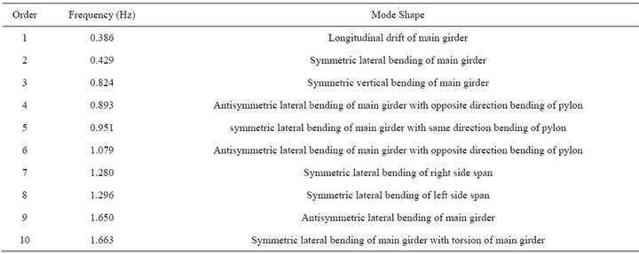
Table 1. List table of first ten natural frequencies and mode shapes.
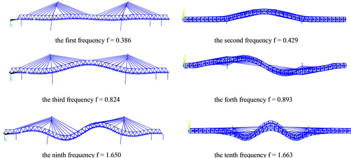
Figure 1. Part space modes of the cable-stayed.
the tenth order of the bridge, its frequency is 1.663 Hz with the symmetric torsion of main girder.
3. Realization of Vehicle-Bridge Coupling Vibration in Multi-Body System
The behavior of the vehicle-bridge system is a complex coupled time-varying dynamic problem. Such a problem is generally solved by a numerical simulation based on a dynamic interaction model for the whole vehicle -bridge system. Theoretically, the analysis model for the vehiclebridge system is composed of two subsystems, the moving vehicle subsystem and the bridge subsystem, which are simulated as two elastic substructures, each of them characterized by some vibration patterns. The two subsystems interact with each other through the contact forces between the wheels and the rail surface.
3.1. Multi-Body Dynamics Model of Vehicle
Multi-body system dynamics is adopted to establish the vehicle system 3-D model [3]. The inter-relationship between each body is realized by the force element which reflects complex features and motion constraint hinge for realizing the stylized modeling, and multi-body dynamics equations are formed automatically. The defects of traditional derivation method are corrected by the proposal modeling method, so it is considered to be powerful evidence of a breakthrough in the vehicle dynamics.
In the multi-body dynamics modeling and simulation of the vehicle system, the characteristics and connection of each body in the vehicle can be confirmed by the definition of rigid body, hinge, constraint, force element, wheel-rail contact model and so on, and then a series of dynamic governing equations are formed [4], the vehicle dynamics model can be divided into three parts from the viewpoint of spring suspension system, car body, boogie and wheel-set. The German ICE Electric Multiple Unit (EMU) train calculation model is set up by multi-system dynamics software SIMPACK. Wheel-set is linked to the bogie frames through the primary suspension, and the bogie frames is linked to the car body through the secondary suspension. Not only two dampers, two snakelike movement dampers and two vertical dampers, but also elastic lateral stoppers are assembled between the car body and bogie. There are 42 degree of freedom in the vehicle model with 34 singlehinges and 8 constraints. And the Multi-body dynamics model of locomotive is shown in Figure 2. The composition of the train is 2 × (locomotive + trailer + 3 × locomotive + trailer + locomotive), and the total number of cars is 16, the multibody dynamics model of train is shown in Figure 3.
Based on the theory of multi-body dynamic system, the equations of motion for the ith vehicle can be derived as follows:

Figure 2. Multi-body dynamics model of locomotive.
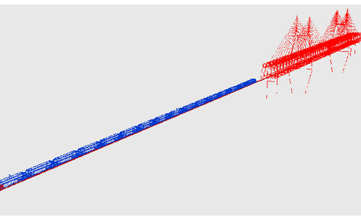
Figure 3. Simulation model of coupled vibration.
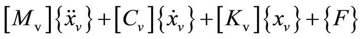 (1)
(1)
where ,
,  and
and  denote the mass, damp and stiffness matrices of vehicle respectively;
  denotes the column vector of general unknown displacement,
  and
and .
.  denotes the column vector of exciting forces.
3.2. Co-Simulation of SIMPACK and ANSYS
An effective strategy has been provided by co-simulation to solve the coupled vibration problem of vehicle-bridge system. And in the light of the principle of co-simulation, the initial value of the vehicle and bridge are independently solved through their appropriate methods. Finite element method is a powerful tool to analyze dynamic behavior of the bridge accurately, and the multi-body dynamics method is adopted to achieve the vehicle dynamics behavior which contains the complex wheel-rail relationship, then the co-simulation of coupled vehicle-bridge vibration is realized through the wheel-rail data exchange preprocessing program at the discrete information points of wheel-rail contact surface [5,6]. The data exchange process of co-simulation based on SIMPACK and ANSYS is detail described in the reference [7]. The normal force between wheel and rail is determined by Hertz nonlinear contact theory, and the vertical and horizontal creep forces is obtained aided by the equivalent Hertz contact characteristics and Kalker’s simplified nonlinear rolling contact theory-FASTSIM Algorithm [8].
4. Calculation and Analysis of Vehicle-Bridge Coupled Vibration
The 3-D dynamic responses, such as the maximum vertical and lateral vibration acceleration of the vehicle, comfort index, rate of wheel load reduction, derailment coefficient, axle lateral force, vertical and horizontal dynamic displacement of the bridge, vibration acceleration of the bridge, dynamic coefficients and so on, are calcu lated by the co-simulation of multi-body system dynamics and finite element method when the ICE EMU train passes the long span cable-stayed bridge at different speeds. Then the responses mentioned above are evaluated according to the current specification requirement. Germany low-interference spectrum is adopted as the excitation of track irregularity during the calculation, and vertical, horizontal, longitudinal and gauge irregularities are taken into consideration and the samples of these four kind irregularities are obtained by the trigonometric series. There are four speed cases, 250, 270, 290 and 300 km per hour respectively. The responses of locomotive and trailer are shown in Table 2, and the responses of the bridge under different train operating speeds are shown in Table 3. Comfort index is evaluated by Sperling index Wz. The reduction rate of wheel weight in the Table 2 is defined as ΔP/P, ΔP is the reduction magnitude of wheel weight at the decrease side of the wheel weight, and P is the static wheel weight.
As shown in Tables 2 and 3, generally speaking the vibration responses of the vehicle and bridge gradually increase along with the speed increase. In all 4 calculation cases, the maximum of derailment coefficient is 0.211, and the maximum of reduction rate of wheel weigh is 0.262. According to the Specification GB- 559985, both of these two indexes are less than the second limit value 1.0 and 0.6 respectively. So the train running safety can be guaranteed. The maximum vertical and lateral acceleration of vehicle are 1.066 m/s2 and 0.681 m/s2 respectively, both of these two indexes are less than their corresponding limits values, 1.3 and 1.0 m/s2. Both the vertical and lateral comfort index is less than 2.5, which means the comfort index is “excellent”. The maximum of vertical displacement in the mid-span of main span is 123.688 mm, the vertical deflection-span ratio is 1/1843 correspondingly, and the maximum of lateral displacement in the mid-span of main span is 2.749 mm, the lateral deflection-span ratio is 1/83,000 correspondingly. The maximum vertical acceleration of bridge is 0.386 m/s2 while lateral acceleration is 0.107 m/s2. The maximum of dynamic coefficient is 1.200. All of these results show that the bridge has a good vibration performance.

Table 2. Responses of locomotive and trailer.
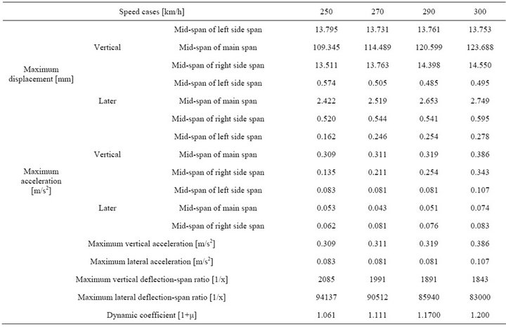
Table 3. Responses of the bridge under different train running speeds.
5. Conclusion
The refined simulation model of the Germany ICE Electric Multiple Unit (EMU) train is set up by multi-system dynamics methods. Then the dynamic analysis model of the cable-stayed bridge is established by finite element method. Finally the dynamic responses of vehicle-bridge coupled vibration are analyzed by co-simulation based on multi-body system dynamics and finite element method when the ICE EMU train passes the long span cable-stayed bridge. From the co-simulation analysis, the derailment coefficient, reduction rate of wheel weight, vertical and lateral acceleration of the vehicle are met the specification requirements, and both the vertical and lateral comfort index are “excellent” when the ICE EMU train passes the bridge at different working conditions. The results also show that it is safe when the train moving through this bridge at the design speed of 250 km per hour with enough running safety and comfort margin for the vehicle, and the bridge structure owns good dynamic performance.
6. Acknowledgements
The research reported herein has been conducted as part of the result of a series of research projects granted by the Chinese National Science Foundation with 51078316, Chinese Railway Ministry Science and Technology Research and Development Program with 2011G026-E & 2012G013-C, and Sichuan Province Science and Technology Project with 11JC0318.
REFERENCES
- W. H. Guo, X. R. Guo and Q. Y. Zeng, “Vibration Analysis of Train-Bridge System for Cable-Stayed Bridge Scheme of Nanjing Yangtse Bridge on Beijing-Shanghai High Speed Railway [J],” China Civil Engineering Journal, Vol. 32, No. 3, 1999, pp. 23-26.
- X. Z. Li and S. Z. Qiang, “Vehicle-Bridge Dynamic Analysis for Long Span Highway and Railway Bi-Purpose Cable-Stayed Bridge [J],” Journal of Vibration and Shock, Vol. 22, No. 1, 2003, pp. 6-26.
- Z. S. Chen and C. G. Wang, “Railway Vehicle Dynamoics and Control [M],” China Railway Press, Beijing, 2004.
- B. R. Miu, W. H. Zhang, S. N. Xiao, et al., “Car-Body Fatigue Life Simulation Based on Multi-Body Dynamics and FEM [J],” Journal of the China Railway Society, Vol. 29, No. 4, 2007, pp. 38-42.
- S. Dietz, G. Hippmann and G. Schupp, “Interaction of Vehicles and Flexible Tracks by Co-Simulation of MultiBody Vehicle Systems and Finite Element Track Models [J],” Vehicle System Dynamics Supplement, Vol. 37, 2003, pp. 372-384.
- S. G. Cui, “Refined Simulation Research of Vehicle-Bridge Coupled Vibration Based on the Multi-Body System Dynamics and Finite Element Method [D],” Southwest Jiaotong University, Chengdu, 2009.
- S. G. Cui, B. Zhu and Z. T. Huang, “Comparative Analysis of Different Wheel/Rail Contact Models in Vehicle and Bridge Coupled Vibration [J],” Chinese Journal of Applied Mechanics, Vol. 27, No. 1, 2010, pp. 63-67.
- J. J. Kalker, “A Fast Algorithm for the Simplified Theory of Rolling Contact,” Vehicle System Dynamics, Vol. 11, No. 1, 1982, pp. 1-13. doi:10.1080/00423118208968684