Open Journal of Earthquake Research
Vol.3 No.1(2014), Article ID:42977,4 pages DOI:10.4236/ojer.2014.31001
Numerical Analysis of Seismic Elastomeric Isolation Bearing in the Base-Isolated Buildings
1Department of Mechanical Engineering, Universiti Tenaga Nasional, Selangor, Malaysia
2Department of Civil Engineering, Islamic Azad University, Kerman Branch, Kerman, Iran
Email: ali_karbakhsh@yahoo.com
Copyright © 2014 M. Jabbareh Asl et al. This is an open access article distributed under the Creative Commons Attribution License, which permits unrestricted use, distribution, and reproduction in any medium, provided the original work is properly cited. In accordance of the Creative Commons Attribution License all Copyrights © 2014 are reserved for SCIRP and the owner of the intellectual property M. Jabbareh Asl et al. All Copyright © 2014 are guarded by law and by SCIRP as a guardian.
Received November 15, 2013; revised December 17, 2013; accepted January 25, 2014
KEYWORDS
Base-Isolated Structure; Seismic Isolation Bearing; Laminated Rubber Bearing; Finite Element Analysis
ABSTRACT
Base isolation concept is currently accepted as a new strategy for earthquake resistance structures. According to different types of base isolation devices, laminated rubber bearing which is made by thin layers of steel shims bonded by rubber is one of the most popular devices to reduce the effects of earthquake in the buildings. Laminated rubber bearings should be protected against failure or instability because failure of isolation devices may cause serious damage on the structures. Hence, the prediction of the behaviour of the laminated rubber bearing with different properties is essential in the design of a seismic bearing. In this paper, a finite element modeling of the laminated rubber bearing is presented. The procedures of modeling the rubber bearing with finite element are described. By the comparison of the numerical and the experimental, the validities of modelling and results have been determined. The results of this study perform that there is a good agreement between finite element analysis and experimental results.
1. Introduction
The use of seismic isolation devices for buildings and bridges has been gaining worldwide acceptance and a well recognized approach to anti-seismic design. The seismic isolation method is generally preferred over more traditional methods, which rely mainly on strengthening of structural elements. This innovative technology reduces the earthquake forces transmitted to the superstructure and therefore eliminates permanent damage to the structure itself, protecting contents and secondary elements. The basic feature of a base isolation system is that the superstructure vibrates almost like a rigid body due to the combination of the flexibility and energy dissipation mechanisms of the components of the base isolation system. The seismically isolation reduces the natural frequency of the isolated structure rather than the same building, if conventionally founded, and the dominant frequencies of a strong ground motion [1,2].
The flexibility of the base-isolation structure is usually achieved by providing elastomeric bearings made of rubber reinforced with steel. The laminated rubber bearings for base isolation devices are made of alternating thin horizontal layers of natural or synthetic rubbers bonded to steel plates. In the concept of base isolation, the steel plates provide large stiffness under vertical load, while the rubber layers provide low horizontal stiffness, when the structure is subjected to lateral loads (e.g., earthquake, wind, etc.). The devices are usually subjected either to compression or to a combination of compression and shear [3]. The great advantage of elastomeric bearings is that: they have no moving parts; they are not subject to corrosion and they are reliable, cheap to manufacture and need no maintenance [4,5].
In the base-isolated buildings, the laminated rubber bearings, being as protectors of the superstructure, should sometimes be protected from failure or instability because the failure of rubber bearings may result in serious damage to superstructure. The evaluation of the collapse conditions is an essential step in designing the rubber bearing. The collapse of the device can occur either by global failure, due to buckling or roll-out of the device [6], or by local rupture, due to tensile rupture of the rubber, through detachment of the rubber from the steel or steel yielding [7]. Therefore, it is necessary to have an accurate knowledge of the global characteristics and behaviour of the device under maximum lateral displacement in compression and shear loads.
A finite element model has the potential for being a powerful tool to be used for improving the knowledge of the local behaviour of the isolation devices. Simo and Kelly, [4] used the finite element modelling to study the variation of lateral load-displacement behaviour under increasing axial load by consideration about 2-D model. Finite element analyses of a circular elastomeric bearing subjected to vertical loads have been performed by Imbimbo and Luca, [7]. Doudoumis et al., [8] have done the numerical modelling of Lead-Rubber Bearings with the use of finite element micromodels and it has shown that the finite element micromodels provide increased possibilities for a more detailed study of the stress, strain and available strength of Lead-Rubber Bearings. However, at previous finite element modelling, there is no brilliant comparison between theoretical and numerical model of laminated rubber bearing.
In this research, firstly, the process of modelling of 3- D finite element analysis of a laminated rubber bearing has been explained. Then, by comparing the results of finite element analysis with experimental results, the validity of models has been shown.
2. Numerical Modelling of Laminated Rubber Bearing
The objective of the numerical analysis is to examine and verify the behaviour of laminated rubber bearing with different compression loads and shear forces. In order to verify the behaviour of rubber bearing predicted by the analytical theory, a computer program has been written for calculating the above mentioned formulation. In other hands, to verify the numerical modelling, the general purpose of finite element ABAQUS application [9] is used to model a multilayer rubber bearing.
2.1. Determination of Material Parameters and Dimensions
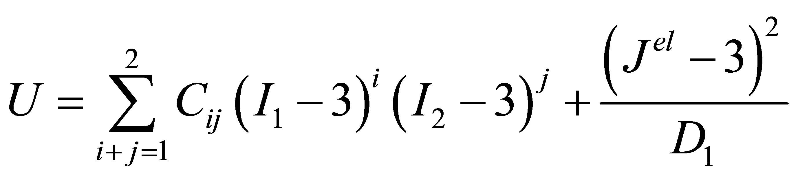
Rubbers are usually considered as almost incompressible material including nonlinear geometric effects. The mechanical rubber behaviour is modelled by a homogeneous, isotropic and hyperelastic model and it is usually described in terms of a strain energy potential U, which defines the strain energy stored in the material per unit of reference volume in the initial configuration as a function of the strain at that point in the material [10]. The rubber is selected as a polynomial hyperelastic material of the second order. In this case, the strain energy potential has the form as follows:
 (1)
(1)
where Cij and D1 are the material parameters, I1 and I2 are the first and the second invariants of the deviatoric strain, and Jel is the elastic volume ratio.
An almost incompressible (neo-Hookean) model has been considered. The material parameters of the rubber can be expressed in terms of initial shear modulus G, and initial bulk modulus K via G = 2(C10), K = 2/D1 [9]. Since D1 is not equal to zero, this model allows some compressibility in the rubber material. The values of the neoHookean coefficients and material properties of the laminated rubber bearing and steel shims are shown in Table 1. The steel material of the top and bottom plates and the shims was assumed to be mild steel, bilinear elastoplastic constitutive law. However, in the simulation of the laminated rubber bearings yielding of steel plate did not occur.
2.2. Numerical Example and Bearing Properties
The experimental data provided by Tsai and Hsueh, [11] are used to validate the comparison between theoretical and numerical modelling. Figure 1(a) shows the laminated rubber bearing with the following dimensions: The steel shim radius R1 = 140 mm, with an additional 10 mm of protective rubber covering, for a total radius of R2 = 150 mm, the number of rubber layers nr = 20 with thickness tr = 10 mm, the total rubber thickness is t = 200 mm, the number of steel shims ns = 19 with thickness ts = 2 mm, and each one of the top and bottom end steel plates is 21 mm. The shear modulus of the rubber material G is 0.611 MPa.
2.3. Finite Element Modelling
The finite element models of the above-mentioned elastomeric isolators have been developed and implemented
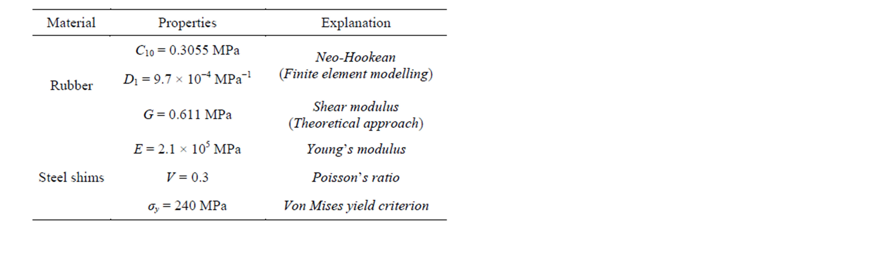
Table 1. Material properties of the selected laminated rubber bearing.
in computer code ABAQUS [9]. The hybrid C3D8H element and reduced integration element, C3D8R of ABAQUS have been used to model rubber and steel shims respectively. The finite element model consists of 49,813 nodes and 27,049 elements. Figure 1(b) shows the meshing of the rubber bearing. Each layer of rubber and steel shim plate is divided into 3 and 2 layers respectively. In order to simulate the real rubber bearing, the central hole (20 mm diameter) is modelled. The hole is used during manufacturing phase and for a better heat exchange during vulcanisation process. The rubber cover is also included in the consideration which is not considered in the previous finite element modelling of laminated rubber bearings [8,12].
The laminated rubber bearing is first compressed with vertical load. Subsequently, the bearing is sheared by applying shear force through the effective area of top end plate keeping the vertical force constant. The applied shear force is increased until the required level of deformation is reached. A typical deformed shape of half of laminated rubber bearing under these loading conditions is given in Figure 2. At the next step, the vertical load is increased and keeping constant then the shear forces are applied frequently. At each step of loading, the maximum lateral displacement of the top end plate to measure the horizontal stiffness is extracted with respect to applied shear force. Other requirements like internal rotation of steel shims and stress concentration at rubber bearing and steel shims are measured as well.
3. Results and Discussions
In the past, researches in the stability issue of laminated rubber bearings show that the P-∆ effect causes the horizontal stiffness to decrease with an increase in the compression force [11,13,14]. A theoretical curve, calculated from Haringx’s theory, results of finite element analysis, and experimental data presented by Tsai and Hsueh, [11] is shown in Figure 3.
As shown in Figure 3, the experimental work has been
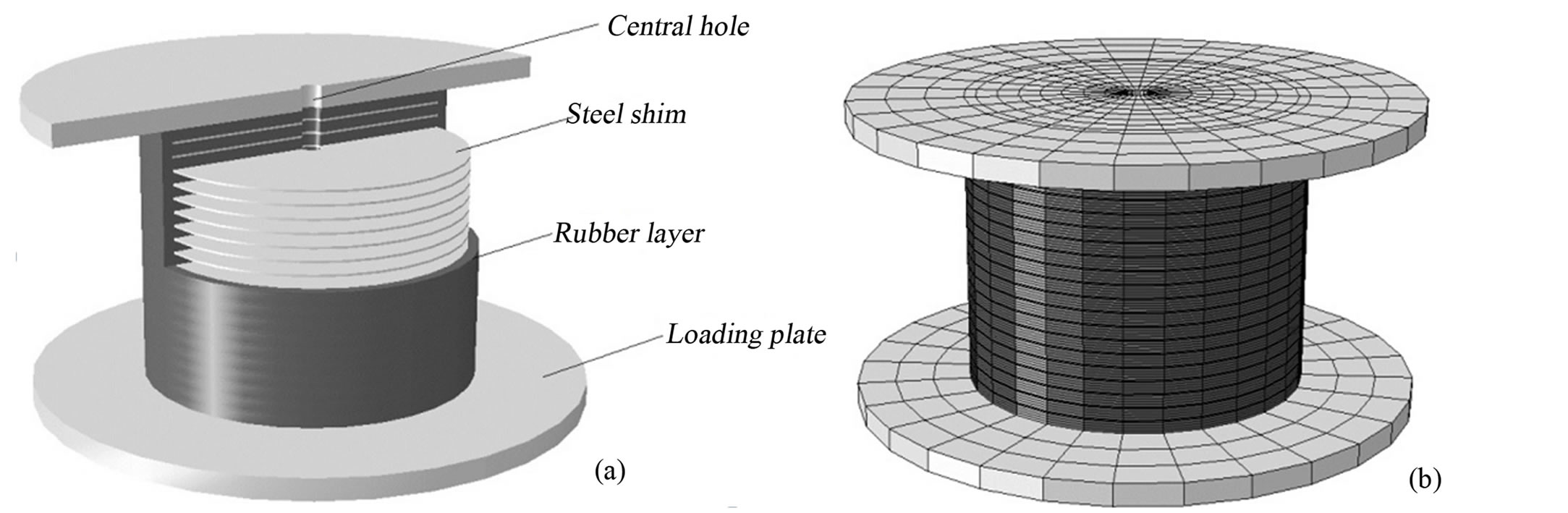
Figure 1. (a) Laminated rubber bearing (b) Finite element mesh.
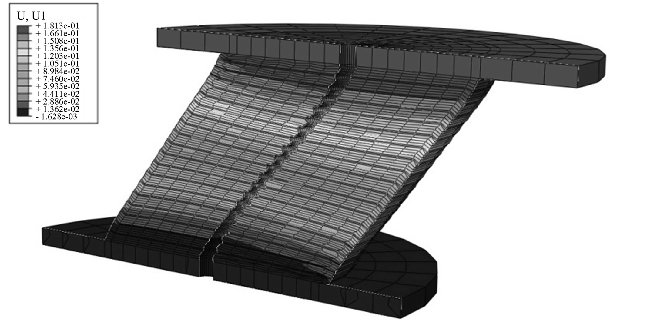
Figure 2. Deformed shape of half part of rubber bearing mesh.
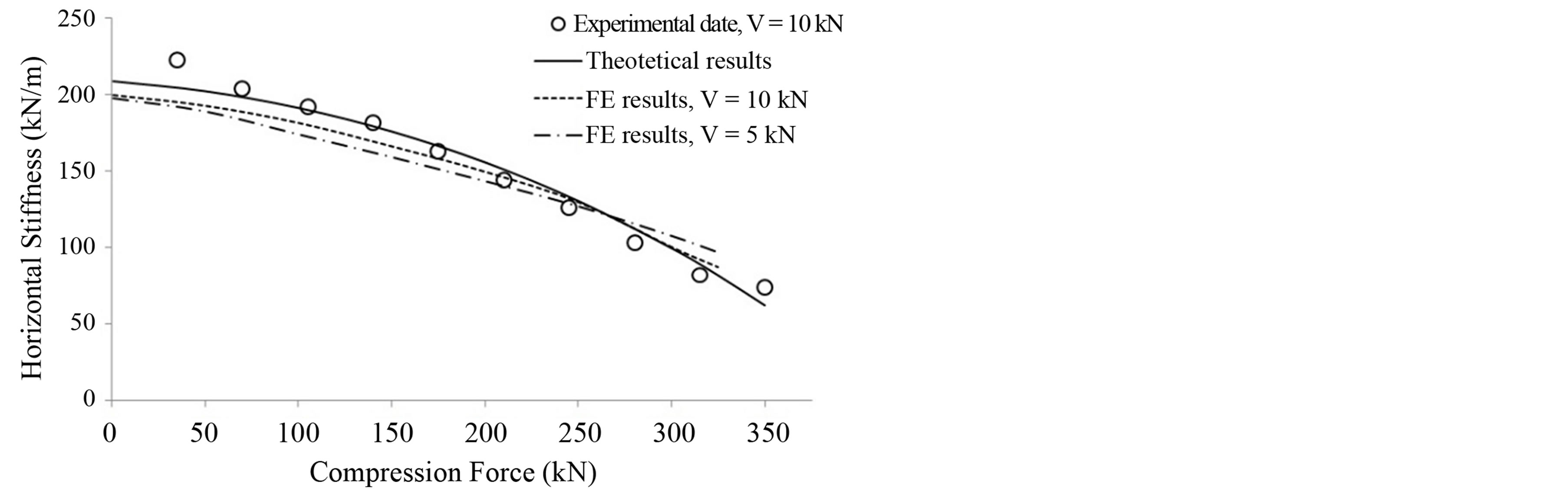
Figure 3. Comparisons of theoretical, finite element and experimental results of horizontal stiffness with compression force.
done with consideration of shear force equal to 10 kN. However, the results of theoretical method are independent of shear force, whereas; the finite element modelling was done with various values of shear forces. Figure 3 shows the results of finite element analysis with consideration of shear forces equal to 5 kN and 10 kN and it shows that the shear force affected the variation of horizontal stiffness of laminated rubber bearings slightly. The slight difference between theoretical and numerical is because the central hole and rubber cover were not considered in the theoretical study, whereas; in the finite element analysis, whole specifications of the laminated rubber bearing were modelled. Figure 3 shows good agreement between the experimental, theoretical and numerical analysis and the validity of finite element results are shown appropriately by this figure.
4. Conclusions
In this paper, the comparison between the finite element analysis and experimental results of a laminated rubber bearing has been performed. Using computer code ABAQUS, numerical simulation of rubber bearing test is compared with theoretical formulation. The comparison of variations of horizontal stiffness of rubber bearing confirms that simulation results have satisfactory agreement with the test results and analytical solution. Concerning the numerical results, it can be noted that varying the values of shear forces affects the horizontal stiffness and maximum lateral displacement which cannot be observed in analytical solution.
Hence, the finite element modelling provides more detailed study of the rubber bearing and a better understanding of their mechanical behaviour. Therefore, the use of finite element modelling in the study of laminated rubber bearings would be advisable.
REFERENCES
- F. Naeim and J. M. Kelly, “Design of Seismic Isolated Structures from Theory to Practice,” John Wiley & Sons, Hoboken, 1999. http://dx.doi.org/10.1002/9780470172742
- X. Y. Zhou, M. Han and I. Yang, “Study on Protection Measures for Seismic Isolation Rubber Bearings,” Earthquake Technology, Vol. 40, 2003, pp. 137-160.
- A. F. M. S. Amin, S. I. Wiraguna, A. R. Bhuiyan and Y. Okui, “Hyperelasticity Model for Finite Element Analysis of Natural and High Damping Rubbers in Compression and Shear,” Engineering Mechanics, Vol. 132, No. 1, 2006, pp. 54-64. http://dx.doi.org/10.1061/(ASCE)0733-9399(2006)132:1(54)
- J. C. Simo and J. M. Kelly, “Finite Element Analysis of the Stability of Multilayer Elastomeric Bearings,” Engineering Structures, Vol. 6, No. 3, 1984, pp. 162-174. http://dx.doi.org/10.1016/0141-0296(84)90044-0
- A. Karbakhsh Ravari, I. B. Othman, Z. B. Ibrahim and K. Ab-Malek, “P-Δ and End Rotation Effects on the Influence of Mechanical Properties of Elastomeric Isolation Bearings,” Journal of Structural Engineering-ASCE, Vol. 138, No. 6, 2012, pp. 669-675. http://dx.doi.org/10.1061/(ASCE)ST.1943-541X.0000503
- J. M. Kelly, “Earthquake-Resistant Design with Rubber,” Springer, Berlin, 1997. http://dx.doi.org/10.1007/978-1-4471-0971-6
- M. Imbimbo and A. D. Luca, “F. E. Stress Analysis of Rubber Bearings under Axial Loads,” Computers & Structures, Vol. 68, No. 1-3, 1998, pp. 31-39. http://dx.doi.org/10.1016/S0045-7949(98)00038-8
- I. N. Doudoumis, F. Gravalas and N. I. Doudoumis, “Analytical Modeling of Elastomeric Lead-Rubber Bearings with the Use of Finite Element Micromodels,” Proceedings 5th GRACM International Congress on Computational Mechanics, Limassol, 2005.
- “ABAQUS 6.2 User Manual, Version 6.2,” HbbitKarlsson Sorensen Inc., Pawtucket, 2001.
- J. Yan and J. S. Strenkowski, “A Finite Element Analysing of Orthogonal Rubber Cutting,” Materials Processing Technology, Vol. 174, No. 1-3, 2006, pp. 102-108. http://dx.doi.org/10.1016/j.jmatprotec.2005.02.265
- H. C. Tsai and S. J. Hsueh, “Mechanical Properties of Isolation Bearings Identified by a Viscoelastic Model,” Solids and Structures, Vol. 38, No. 1, 2001, pp. 53-47. http://dx.doi.org/10.1016/S0020-7683(00)00010-X
- J. M. Kelly and S. M. Takhirov, “Tension Buckling in Multilayer Elastomeric Isolation Bearings,” Mechanics of Materials and Structures, Vol. 2, No. 8, 2007, pp. 1591- 1605. http://dx.doi.org/10.2140/jomms.2007.2.1591
- A. Karbakhsh Ravari, I. Othman, Z. Ibrahim and H. Hashamdar, “Variations of Horizontal Stiffness of Laminated Rubber Bearings Using New Boundary Conditions,” Scientific Research and Essays, Vol. 6, No. 14, 2011, pp. 3065-3071.
- C.-H. Chang, “Modeling of Laminated Rubber Bearings Using an Analytical Stiffness Matrix,” International Journal of Solids and Structures, Vol. 39, No. 24, 2002, pp. 6055-6078. http://dx.doi.org/10.1016/S0020-7683(02)00471-7