Open Journal of Applied Biosensor
Vol.1 No.3(2012), Article ID:24548,5 pages DOI:10.4236/ojab.2012.13003
A Microfluidic Reactor for Energy Applications
1Department of Mechanical Engineering, Iowa State University, Ames, USA
2Department of Civil Engineering, TarbiatModares University, Tehran, Iran
Email: *nastaran@iastate.edu
Received August 20, 2012; revised September 30, 2012; accepted October 15, 2012
Keywords: Microfluidic; Microbial Fuel Cell; Renewable Energy; Biochemical Process
ABSTRACT
Miniature microbial fuel cells have recently drawn lots of attention as portable power generation devices due to their short startup time and environmentally-friendly process which could be used for powering small integrated biosensors. We designed and fabricated a microbial fuel cell in a microfluidic platform. The device was made in polydimethylsiloxane with a volume of 4 µL and consisted of two carbon cloth electrodes and proton exchange membrane. Shewanella Oneidensis MR-1 was chosen to be the electrogenic bacterial strain and inoculated into the anode chamber. Ferricyanide was used as the catholyte and pumped into the cathode chamber at a constant flow rate during the experiment. The miniature microbial fuel cell generated a maximum current of 2.59 µA and had a significantly short startup time.
1. Introduction
A microbial fuel cell (MFC) is a biofuel cell used to convert chemical energy into electrical energy through a biochemical process. Microbial fuel cells are specified as such because they use living cells such as microbes to perform the biochemical processes required for electricity generation [1]. A biosensor is an analytical device used for detecting the concentration of certain chemicals [2,3]. Enzymes, antibodies, receptors and microorganisms can be applied as biological sensing elements [4]. Purified enzymes have been used in most biosensor constructions [5-7] because of their specificity and sensitivity [8,9] but disadvantages such as instability and expensive parts have limited their range of applications [9]. MFCs provide unique platforms for potentially powering small portable electronic devices, studies of microbes, and screening environmental strains. They also have the potential to become just as specific and sensitive as enzymes are in the future. They can be used as biosensors in two ways. The first way comes from the need to provide nutrition to the microbes that produce the electricity. This is typically done with some kind of growth medium such as glucose, trypticase soy broth, lactate, or acetate. An MFC could be used to determine the amount of sample nutrition by running that sample into the anodic chamber and observing if a current is produced while running a consistent catholyte through the cathodic chamber.
Alternatively, a consistent growth medium could be fed into the anodic chamber while running a sample through the cathodic chamber to determine if a positive ion is present or even if certain compounds are present. These compounds could be any one of many that are used as a catholyte in MFCs. Some limitations of microbial biosensors have caused them to only be used extensively in academia, such as experiments run in a real environment not performing properly like they do when run in controlled laboratories. However, improvements have been made that help them to perform better in real environments by other groups [10,11]. Microbial biosensors are still a competitive technology, which would benefit from further research and improvement.
Microbial fuel cells are desirable biosensors because of their mild operation conditions (room temperature and neutral pH), short startup time, long running period without recharging [12,13], environmentally friendly reaction process [14] and low cost. Recently, there have been some studies on advantages of the miniature microbial fuel cells [15-17] such as increased power density, shorter start time and faster power generation recovery after refilling. The increased advantages come from the fact that the density of power generation of MFCs depends on the surface area-to-volume ratio, because micro-scale MFCs have a much smaller overall volume. The roughness of the channel surface allows for an increase in this ratio. Electrodes could affect the power density, carbon cloth, Ag/AgCl, sat. KCl, Toray carbon paper, CE PEM and thin film Pt are electrodes that have been used by several research groups. Micro-scale microbial fuel cells are newly developed in the field of MFCs and have a lot of potential for further improvement. Most MFCs use bacteria [14,15,18] or algae [19] as electrogenic microbes. Pure culture has been used more frequently. Binary [20] and multiple cultures are also employed to investigate the effect of biofilm properties on the electrochemical performance of the MFCs.
In this study, we have employed Shewanella MR-1 as the electrogenic microbes and carbon cloth as the electrodes. A micro-scale MFC was fabricated by sandwiching the materials between two Polydimethylsiloxane (PDMS) chambers. We have studied the biofilm formation on the carbon fibers and the power density using this device.
2. Materials and Methods
The chemicals and materials used in the experiment include Nafion® membrane (Nafion<® 115, Ion Power, New Castle, DE), carbon cloth (Fuel Cell Earth, Stoneham, MA), 184 silicone elastomer (Dow Corning, Midland, MI), 0.5 mm titanium wire (Sigma Aldrich, St. Louis, MO), 1.25” inner diameter polyethylene tubing (Dow Corning, Midland, MI), trypticase soy broth (Sigma Aldrich, St. Louis, MO), and phosphate buffered saline (Sigma Aldrich, St. Louis, MO).
Shewanella Oneidensis MR-1 was cultured aerobically in trypticase soy broth (TSB). The culture was scraped onto TSB and allowed to grow for a day. The culture was then put into the refrigerator for preservation. The bacteria soaked in TSB were then transferred from the plate to a syringe. The TSB and bacteria mixture were injected into the MFC to start the current generation. The same mixture was used in a fed-batch process throughout the entire length of the experiment.
Chambers were fabricated from a thermoplastic master. The chamber design was printed to thermoplastic sheets and then shrunk in the oven. The sheets shrunk isotropically by 63% and the ink rose to some height which was dependent on the original print quality. Heating the thermoplastic sheet to 160˚C for 8 minutes we were able to achieve a chamber height of 100 μm. PDMS chambers were made from this mold instead of the conventional silicon wafer.
The MFC device was assembled by putting a Nafion® 115 proton exchange membrane (PEM) and two carbon cloth electrodes between the two chambers (Figure 1). The carbon cloth electrodes were sized approximately 10 × 4 mm, the same as the chamber and were electrically connected with titanium wire of diameter 0.5 mm. The assembly was held together using binder clips on all four sides. The anolyte (growth medium) and catholyte (ferricyanide) were introduced into the microchannel through polyethylene tubing with inner diameter 1.25 mm.
The entire assembled MFC was autoclaved at 120˚C for 15 minutes before bacterial inoculation. We then connected the electrodes together by a 10 kΩ resistor. The potential drop over the resistor was measured as a function of time in 10 minute intervals. Ferricyanide catholyte (50 mM K3Fe (CN) 6 in a 100 mM pH 7.4 phosphate buffered saline) was running through the cathode chamber using a syringe pump (Figure 2). The experiment took place under ambient light condition providing a consistent light.
The current generated by the MFC was recorded as a function of time by measuring the potential drop, V, across the 10 kΩ resistor, R. We then calculated current, I, using Ohm’s law: I = V/R. Current density was calculated using the projected anode area.
3. Results and Discussion
Data was recorded first without bacteria. A current of 0.5 nA was obtained when only medium and ferricyanide were running through the device. This value was considered as the background current caused by the flow in anode and cathode chambers. After we introduced Shewanella MR-1, current increased immediately. Figure 3 represents thirty five hours of data collection after injection of Shewanella MR-1.
TSB medium was refilled once the current dropped to the baseline. After the first refill, a peak value of 2.31 µA was obtained in ten minutes. This shows a significantly faster startup time over macro-scale microbial fuel cells. This improvement is considered an advantage of miniature MFCs. Smaller volume-to-surface ratio enables a better contact between bacteria and electrode, thus providing a more electrically sensitive system. Current started dropping after the maximum value was reached. The current reading obtained one hour later was 1.03 µA, which indicates the current had dropped to 45% of its peak value. The decreasing of current slowed down after six hours of TSB refill, and stayed between 0.2 to 0.4 µA for three hours. For the first cycle of refill, current had stayed above 1 µA for one hour. Second refill of TSB

Figure 1. Micro-scale MFC design andassembly: a microscopy image, a photograph of thermo-plastic master, and individual components of the MFC. The device is assembled by sandwiching a PEM between the two PDMS chambers. Each chamber has its own carbon cloth electrode.
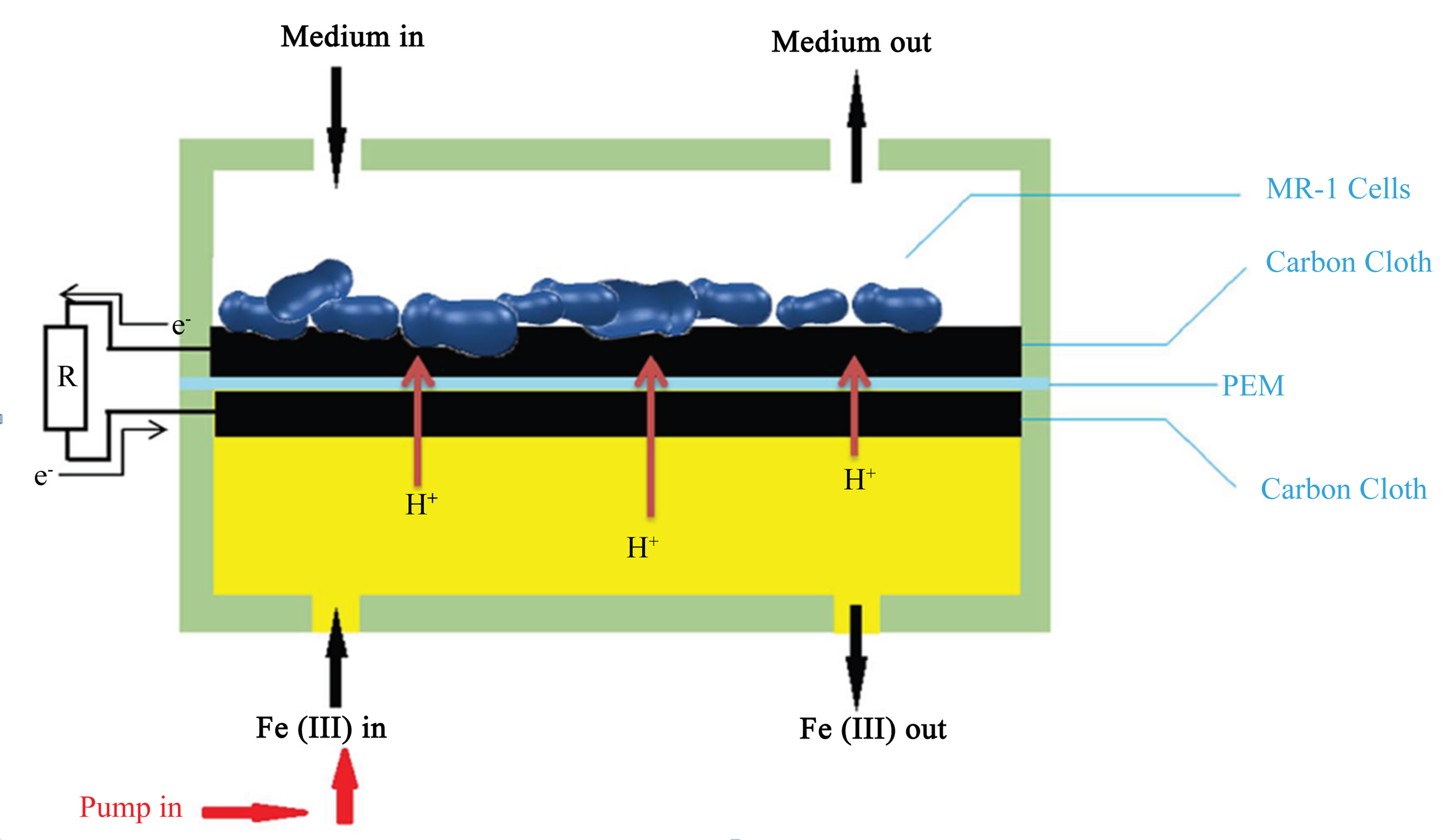
Figure 2. Medium flows through the anode chamber as indicated by the arrows. Ferricyanide flows through the cathode chamber using a syringe pump at a flow rate of 50 μL/h. The electrons travel from the anode through the 10 kΩ resistor to the cathode. Protons are exchanged through the PEM.
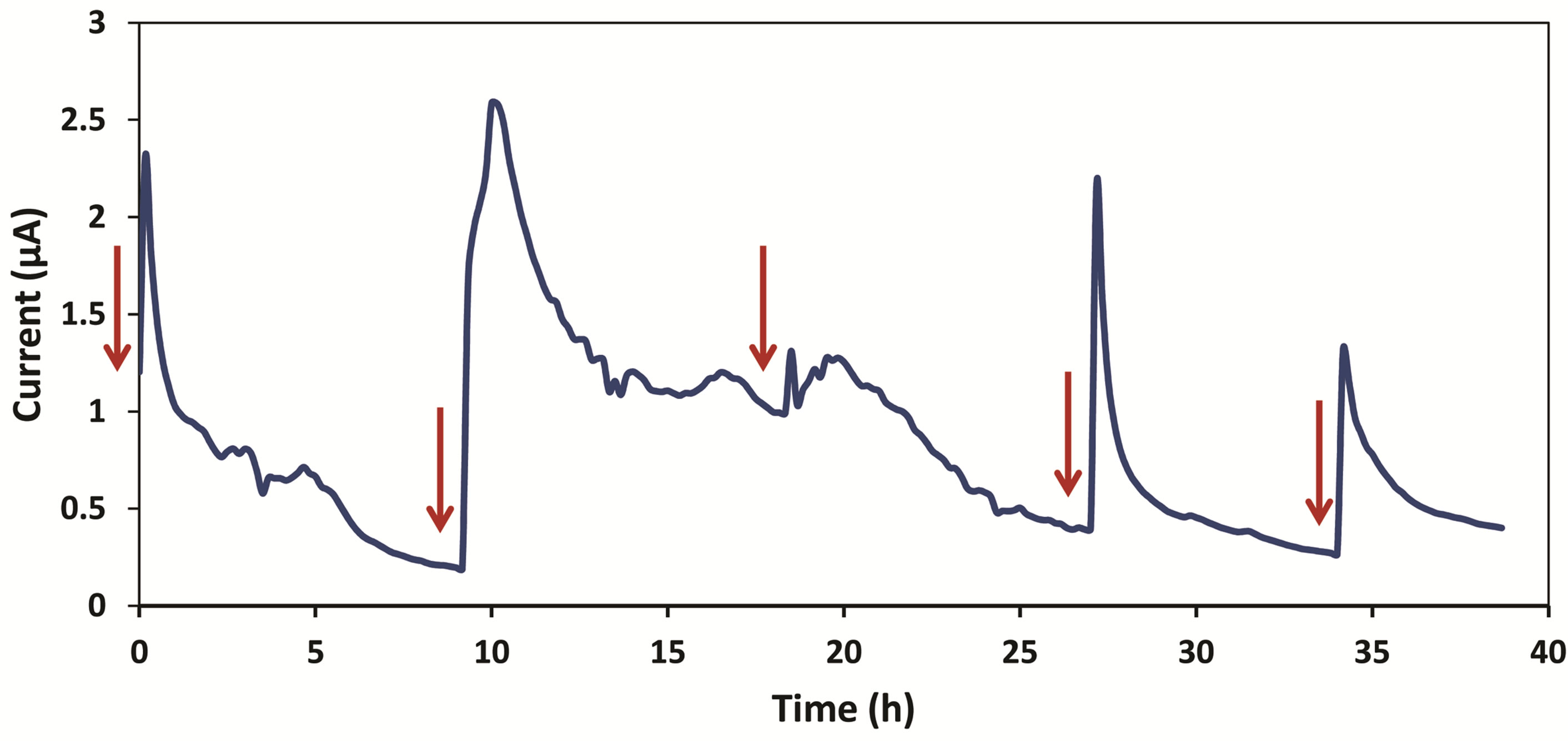
Figure 3. This graph shows current vs. time starting from thirty five hours after introduction of Shewanella MR-1 into the device. Each refill is shown by a red arrow.
medium was done ten hours after the first one. Current increased instantly from 0.2 µA to a peak value of 2.59 µA in thirty minutes. Then it dropped to 1.2 µA four hours after the refill, and stayed slightly above 1 µA for four hours. We observed only a slight increase in current during the third refill. The current remained higher than 1 µA for four hours and decreased smoothly over time.
Another refill was made after the current became steady (roughly ten hours). A peak current of 2.16 µA was reached within ten minutes. The current had a consistent fall for about seven hours before becoming steady again around 0.28 µA. The last refill was done thirty five hours after the first refill. A maximum current of 1.32 µA was reached for this experiment period. The current dropped to 0.4 µA and became constant.
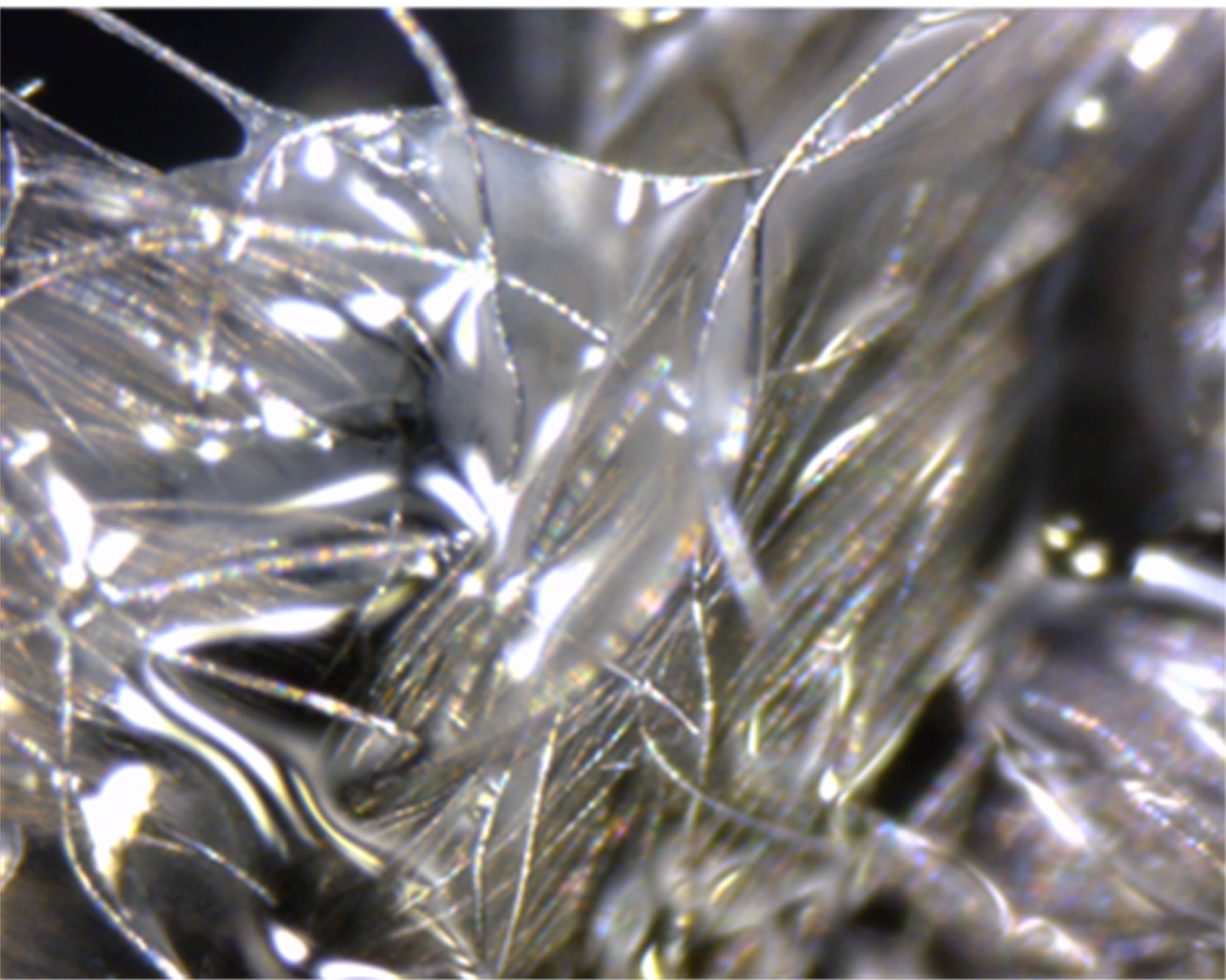
Figure 4(a) shows a biofilm covering the carbon fibers after five days of experiment operation. This confirms the current obtained during the experiment was generated by electrically conductive biofilms. A picture of new carbon cloth without biofilm is also taken using digital microscope for comparison (shown in Figure 4(b)).
The faster startup time of the micro-scale MFC is a central improvement over the macro-scale counterparts. Also, these micro-scale MFCs are considered to be more sensitive because of their rapid response to the electro-
 (a)
(a) (b)
(b)
Figure 4. (a) A microscopy image of a biofilm formation on the carbon cloth after being used in the MFC device. (b) A microscopy image of a new, unused carbon cloth.
chemical changes occurring in the chambers. The miniature MFCs could be used for further studies of microbial communities as well.
4. Conclusion
A 4 µL MFC device fabricated with PDMS was demonstrated to generate a current of up to 2.59 µA in a reproducible manner. The MFC was fabricated easily and quickly through a non-photolithographic approach. It was demonstrated that the MFC can produce current peaks through using Shewanella Oneidensis MR-1 as the biocatalyst.
5. Acknowledgements
We are grateful for the research support provided by the Iowa State University and William March Scholar Fund. The authors would like to thank the Bioeconomy Institute at Iowa State University, Dr. Laura Jarboe, and Dr. Zhiyou Wen for their help and insightful comments. We also thank Pouya Asrar and Benjamin Allen for their assistance in preparing the microfluidic devices.
REFERENCES
- I. Ivanov, T. Vidaković-Koch and K. Sundmacher, “Recent Advances in Enzymatic Fuel Cells: Experiments and Modeling,” Energies, Vol. 3, No. 4, 2010, pp. 803-846. doi:10.3390/en3040803
- N. Hashemi, J. S. Erickson, J. P. Golden, K. M. Jackson, and F. S. Ligler, “Microflow Cytometer for Optical Analysis of Phytoplankton,” Biosensors and Bioelectronics, Vol. 26, No. 11, 2011, pp. 4263-4269. doi:10.1016/j.bios.2011.03.042
- N. Hashemi, J. S. Erickson, J. P. Golden and F. S. Ligler, “Optofluidic Characterization of Marine Algae Using a Microflow Cytometer,” Biomicrofluidics, Vol. 5, 2011, Article ID: 032009. doi:10.1063/1.3608136
- Y. Lei, W. Chen and A. Mulchandani, “Microbial Biosensors,” Analytica Chimica Acta, Vol. 568, No. 1-2, 2006, pp. 200-210. doi:10.1016/j.aca.2005.11.065
- S. C. Barton, J. Gallaway and P. Atanassov, “Enzymatic Biofuel Cells for Implantable and Microscale Devices,” Chemical Reviews, Vol. 104, No. 10, 2004, pp. 4867- 4886. doi:10.1021/cr020719k
- S. Boland and D. Leech, “A Glucose/Oxygen Enzymatic Fuel Cell Based on Redox Polymer and Enzyme Immobilisation at Highly-Ordered Macroporous Gold Electrodes,” Analyst, Vol. 137, 2012, pp. 113-117. doi:10.1039/c1an15537g
- P. Jenkins, S. Tuurala, A. Vaari, M. Valkiainen, M. Smolander and D. Leech, “A Mediated Glucose/Oxygen Enzymatic Fuel Cell Based on Printed Carbon Inks Containing Aldose Dehydrogenase and Laccase as Anode and Cathode,” Enzyme and Microbial Technology, Vol. 50, No. 3, 2012, pp. 181-187. doi:10.1016/j.enzmictec.2011.12.002
- L. Su, W. Jia, C. Hou and Y. Lei, “Microbial Biosensors: A Review,” Biosensors and Bioelectronics, Vol. 26, No. 5, 2011, pp. 1788-1799. doi:10.1016/j.bios.2010.09.005
- S. d’Souza, “Microbial Biosensors,” Biosensors and Bioelectronics, Vol. 16, No. 6, 2001, pp. 337-353. doi:10.1016/S0956-5663(01)00125-7
- I. L. Medintz and J. R. Deschamps, “Maltose-Binding Protein: A Versatile Platform for Prototyping Biosensing,” Current Opinion in Biotechnology, Vol. 17, No. 1, 2006, pp. 17-27. doi:10.1016/j.copbio.2006.01.002
- H. H. Park, W. K. Lim and H. J. Shin, “In Vitro Binding of Purified NahR Regulatory Protein with Promoter Psal,” Biochimica et Biophysica Acta (BBA)-General Subjects, Vol. 1725, No. 2, 2005, pp. 247-255. doi:10.1016/j.bbagen.2005.05.015
- E. R. Choban, L. J. Markoski, A. Wieckowski and P. J. A. Kenis, “Microfluidic Fuel Cell Based on Laminar Flow,” Journal of Power Sources, Vol. 128, No. 1, 2004, pp. 54- 60. doi:10.1016/j.jpowsour.2003.11.052
- R. S. Jayashree, L. Gancs, E. R. Choban, A. Primak, D. Natarajan, L. J. Markoski and P. J. A. Kenis, “Air-Breathing Laminar Flow-Based Microfluidic Fuel Cell,” Journal of the American Chemical Society, Vol. 127, No. 48, 2005, pp. 16758-16759. doi:10.1021/ja054599k
- K. Rabaey, G. Lissens, S. D. Siciliano and W. Verstraete, “A Microbial Fuel Cell Capable of Converting Glucose to Electricity at High Rate and Efficiency,” Biotechnology letters, Vol. 25, No. 18, 2003, pp. 1531-1535. doi:10.1023/A:1025484009367
- F. Qian, M. Baum, Q. Gu and D. E. Morse, “A 1.5 µL Microbial Fuel Cell for On-Chip Bioelectricity Generation,” Lab on a Chip, Vol. 9, No. 21, 2009, pp. 3076-3081. doi:10.1039/b910586g
- F. Qian, Z. He, M. P. Thelen and Y. Li, “A Microfluidic Microbial Fuel Cell Fabricated by Soft Lithography,” Bioresource Technology, Vol. 102, No. 10, 2011, pp. 5836-5840. doi:10.1016/j.biortech.2011.02.095
- B. R. Ringeisen, E. Henderson, P. K. Wu, J. Pietron, R. Ray, B. Little, J. C. Biffinger and J. M. Jones-Meehan, “High Power Density from a Miniature Microbial Fuel Cell Using Shewanella oneidensis DSP10,” Environmental Science & Technology, Vol. 40, No. 8, 2006, pp. 2629-2634. doi:10.1021/es052254w
- Z. He, N. Wagner, S. D. Minteer and L. T. Angenent, “An Upflow Microbial Fuel Cell with an Interior Cathode: Assessment of the Internal Resistance by Impedance Spectroscopy,” Environmental Science & Technology, Vol. 40, No. 17, 2006, pp. 5212-5217. doi:10.1021/es060394f
- S. B. Velasquez-Orta, T. P. Curtis and B. E. Logan, “Energy from Algae Using Microbial Fuel Cells,” Biotechnology and Bioengineering, Vol. 103, No. 6, 2009, pp. 1068-1076. doi:10.1002/bit.22346
- Z. Ren, T. E. Ward and J. M. Regan, “Electricity Production from Cellulose in a Microbial Fuel Cell Using a Defined Binary Culture,” Environmental Science & Technology, Vol. 41, No. 13, 2007, pp. 4781-4786. doi:10.1021/es070577h
NOTES
*Corresponding author.