Open Journal of Fluid Dynamics
Vol.3 No.2(2013), Article ID:32624,5 pages DOI:10.4236/ojfd.2013.32004
Dimensional and Mechanical Similarity Analysis of the Flow in Rotating Liquid Film Reactor
Department of Mathematics, Beijing University of Chemical Technology, Beijing, China
Email: xulx@mail.buct.edu.cn
Copyright © 2013 Xue Li et al. This is an open access article distributed under the Creative Commons Attribution License, which permits unrestricted use, distribution, and reproduction in any medium, provided the original work is properly cited.
Received March 26, 2013; revised April 26, 2013; accepted May 6, 2013
Keywords: Rotating Liquid Film Reactor (RLFR); Coaxial Rotating Conical Cylinder; Mechanical Similarity; Reynolds Number; Dimensional Analysis
ABSTRACT
A rotating liquid film reactor (RLFR) is a device of two coaxial rotating conical cylinders with the inner cone rotating and the outer one stationary. A complete mathematical model for the flow between the conical cylinders is built and a dimensional analysis is carried out. It is proved that at each point of the flow field the dimensionless pressure and velocity of the flow are determined by parameters: Reynolds number (Re), aspect ratio (Γ), radius ratio (η) and wall inclination angle (α). Furthermore, a sufficient and a necessary condition are derived from mechanical similarity between RLFR and a manufacturing equipment geometrically similar to RLFR. Finally, a numerical simulation for the distribution of pressure and velocity is performed. The results may provide a theoretical basis for experiment method and numerical simulation of the flow in a RLFR-like device.
1. Introduction
The viscous flow between concentric rotating cylinders, called Taylor-Couette flow (TCF) [1], has been studied by numerous research workers for over 300 years (see [2] and the references therein). This is a classical system to investigate properties of flow driven by rotation. So far, an abundance of experimental and numerical results on TCF are available.
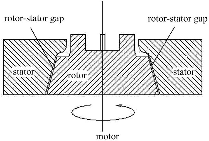
Recently, another configuration related to rotating body has aroused the interest of researchers. A few chemists have constructed a precipitation reactor, called rotating liquid film reactor, which is used as a reactor to prepare new functional nano-particles. It is found that, compared with conventional precipitation reactors, the particles produced in the RLFR are smaller in size and narrower in size distribution [3]. The RLFR consists of two coaxial conical cylinders with the inner cone rotating and the outer one stationary, as displayed in Figure 1. The walls of cones are parallel giving a constant width of the gap for RLFR. The gap between two cones is filled with reactants, which are usually considered as a viscous incompressible fluid. In order to figure out the effect of the RLFR on precipitation, it is necessary to investigate the properties of the flow in the gap. This can be done by experiment and numerical simulation. However, the properties of the fluid flow depend on many parameters, e.g.  (rotor’s angular velocity),
  (viscosity), H (cone’s height),
  (inclination angle of the cone),
  (bottom radius of the inner cone),
  ( bottom radius of the outer cone). In order to reduce the dimension of the problem, it is necessary to conduct a dimensional analysis. The dimensional analysis is also a basis for experiment and numerical simulation. Moreover, the RLFR is very tiny, compared with the manufacturing equipment. The reactor has a height of 17 mm, upper diameter of 40.8 mm, bottom diameter of 50 mm and inclination angle of 75 deg. The gap width can be adjusted in the range of 0.1 mm - 0.5 mm by moving the stator (outer cone). The rotor (inner cone) can rotate at variable speeds up to 5000 rpm by a adjustable-speed motor. One may ask that, to what extent, the flow properties obtained by experiment and numerical simulation for the RLFR could reflect that of the real flow in manufacturing equipment. This is a problem of mechanical similarity. Trying to reduce the dimension and to derive mechanical similarity of this problem are the motivations of our paper. As far as we know, there is no paper dealing with this problem.
So far, the studies of the flow in RLFR have not been given due attention. However, for the upside down device of Figure 1, the properties of the flow in the gap
 (a)
(a) (b)
(b)
Figure 1. The sketch of the coaxially rotating liquid film reactor.
with the inner one rotating and the outer one at rest have been experimentally studied by Wimmer [4,5] and numerically by Noui-Mehidi et al. [6,7], Xu et al. [8,9] and Li et al. [10]. In [4,5] Wimmer studied the stability of basic flow and the transition to Taylor vortices, as well as the occurrence of Taylor vortex at different geometries. Noui-Mehidi et al. [6,7] investigated the effect of wall alignment on the flow and the stability of the helical flow, as well as the transition to turbulence. Xu et al. [8] studied the dependence of the velocity and the pressure magnitude on the cone inclination. In [9] Xu et al. showed that the behavior of the flow is dominated by a competition between the meridional flow and the radial flow. Li et al. [10] discussed the local maximum value of velocity and the local maximum of pressure, as well as the transition to Taylor vortices.
The paper is organized as follows: Mathematical formulation is given to Section 2. Section 3 and 4 are devoted to dimensional analysis and mechanical similarity analysis, respectively. A numerical simulation for the pressure and the velocity is implemented in Section 5. Finally, the conclusions and some discussion are made in Section 6.
2. Mathematical Formulation
Consider the configuration in Figure 1 in which the inner cone and the outer one have the same inclination angle . The gap between two cones is filled with a viscous incompressible fluid. The inner cone rotates at angular velocity
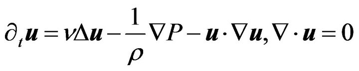
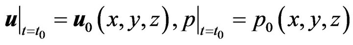
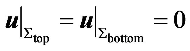
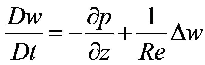
  and the outer one is at rest. It is assumed that the top and the bottom end plate are rigid and the boundary condition at the cone side is no-slip. Then the governing equations with the initial and the boundary conditions are as follows:
 (1)
(1)
 (2)
(2)
 (3)
(3)
 (4)
(4)
where  and
and  denote velocity, density, pressure and kinematic viscosity of the fluid, respectively.
  denote the top end plate, the bottom end plate, inner and outer cone side, respectively.
  is the angular velocity of the cones. We set Cartesian coordinate system as in Figure 1.
Let  be the unit vector along axes of the cylindrical coordinate system, then with
  Equation (1) expressed in cylindrical coordinates are as follows:
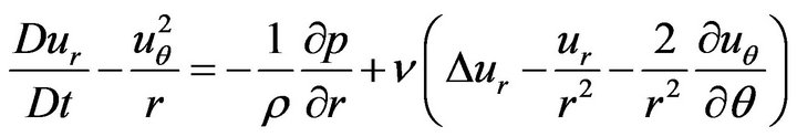 (5)
(5)
 (6)
(6)
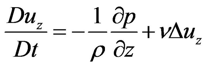 (7)
(7)
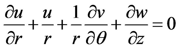
 (the continuity equation) (8)
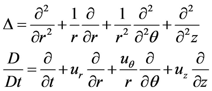
where
The initial and the boundary conditions are presented as follows:
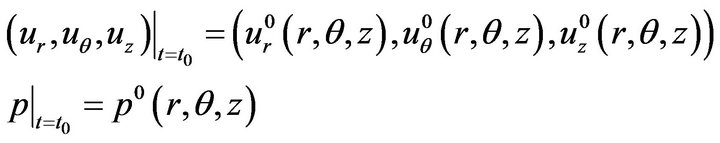 (9)
(9)
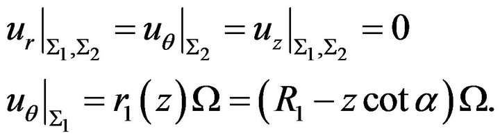 (10)
(10)
3. Dimensional Analysis of the Model
Consider the initial and boundary value problem (5) - (10), by using the following dimensionless quantities
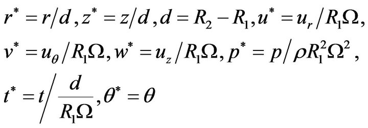
Equations (5)-(8), by removing “*”, can be nondimensionalized into the following ones:
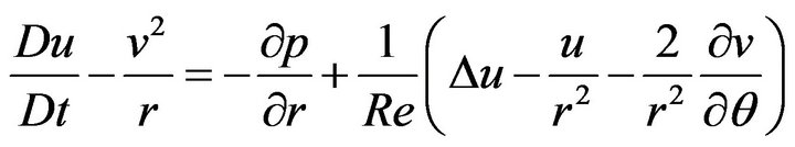 (11)
(11)
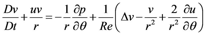 (12)
(12)
 (13)
(13)
 (the continuity equation) (14)
where

and 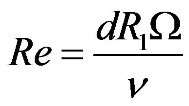 (the Reynolds number).
By removing “*” the dimensionless initial and bounary conditions (9) and (10) resume to following forms:
 (15)
(15)
 (16)
(16)
with  The dimensionless form of boundary condition at the top and bottom end plate remains as
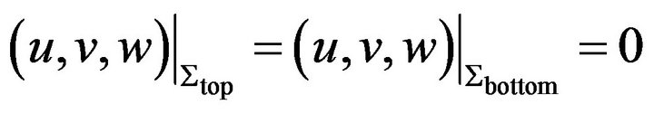 . (17)
Furthermore, we have
thus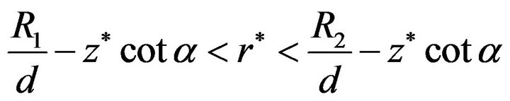 .
.
Removing “*” we have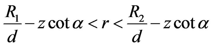 .
.
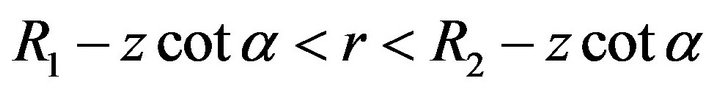
The behavior of fluid in the RLFR is governed by the Equations (11)-(14) with the initial and the boundary conditions (15)-(17). The solving region is:

Letting , together with
 , we obtain
  Together with
the dimensionless solving region becomes:
and the boundary conditions (16) can be written as
 (18)
(18)
According to the symmetry of the boundary conditions the pressure and the velocity of the flow are  -independent and together with the above dimensionless analysis the solution of the problem has the following dependencies:

where  is the so called aspect ratio. Hence we obtain the following theorem:
Theorem 1 Let  be the solution of the initial and boundary value problem (11)-(17), then at any time point and each point of the flow field,
  are determined by the dimensionless parameters: Reynolds number (Re), aspect ratio
 , radius ratio
  and cone inclination angle
 .
.
4. Mechanical Similarity Analysis
We all know that the size of RLFR in laboratory is very tiny, compared with that of the manufacturing equipment (i.e., the actual object), which is geometrically similar to RLFR. Therefore, one obvious question is weather the data obtained by experiment and numerical simulation for the flow in RLFR can characterize the properties of real flow in the actual object. That is the question we like to answer in this section.
We now consider the necessary condition for mechanical similarity of two flows. Assuming that there are two flows with dimensionless velocity  and dimensionless pressure
 , as well as corresponding dimensionless parameters:
  and
and , where
  stands for the first flow and
  the second one. We suppose that the two flows have mechanical similarity, i.e.

where,  and
and  satisfy the dimensionless Equations (11)-(14) with the boundary condition (16)-(17). In order to ensure that two solutions are equal, the solving region
 should be the same one, which leads to
  .
.
From  and
and  satisfying Equation (13) we obtain
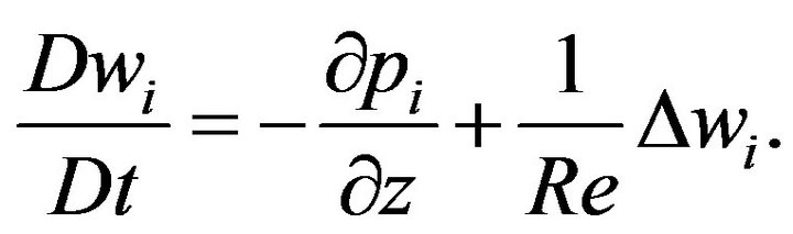
Subtracting two equations and taking account of
 we have
 . Suppose
 we have
 . With the zero-boundary condition of
  and a result of partial differential equation we obtain
  in D, which leads to
 . So it follows that the pressure
 is independent of
 . Due to the change of centrifugal forces in the
  -direction, this is obviously not the fact, hence
 . Summarizing foregoing analysis, we obtain the necessary condition for the mechanical similarity of the two flows as following:

Moreover, with the uniqueness of the solution the sufficient condition for mechanical similarity of the two flows is at hand. Now we formulate our results in following theorem:
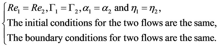
Theorem 2 Assuming that we have two flows with parameters  and
and , then the necessary condition for mechanical similarity of the two flows is:

Moreover, if the Equations (11)-(14) have unique solution, the sufficient condition for mechanical similarity of the two flows is:
5. A Numerical Simulation of Pressure and Velocity Distribution
The nonlinear and the time dependent Equation (1) together with the boundary conditions (3)-(4) and initial conditions  are integrated numerically using the finite volumes method. For the convection terms in equations, a second-order upwind scheme is used to interpolate the face values of the various quantities from the cell center values. Central difference quotient is used for the diffusion terms which are always secondorder accurate. The temporal discretization involves integrating all the terms in the differential equations with a time step
 . The integration of the transient terms is implicit by using a second-order formulation. The SIMPLE algorithm is used to link pressure and velocity. The discretized equations are then solved sequentially using a segregated solver. For the justification of the numerical method, one may refer to [8].
From Sections 3 and 4, we know that the distribution of the pressure and the velocity of the flow depend on  and
and . In this section, we have chosen
  and
and  as examples to calculate the distribution of pressure and velocity as well as the streamline of the flows.
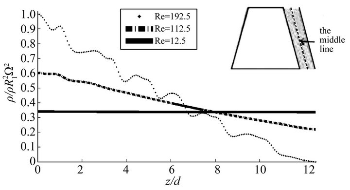
Figure 2 illustrates the numerical results of the distribution of the pressure and the velocity for some parameters of the system. The distribution of the pressure and the velocity is calculated along a line from the midpoint of the bottom end plate to the midpoint of the top end plate in the  -plane for
 . In cylindrical coordinate system the line is given by
 . It is clear that the distribution curves of the pressure and the velocity are approximately a straight line at
 . In this case the streamline of the flow is given in Figure 3(a), which indicates that the basic flow is a 3-dimensional flow for small Reynolds number. The basic flow becomes unstable and the first pair Taylor vortex appears at about Re = 112.5, corresponding a local fluctuation along the distri-
 (a)
(a)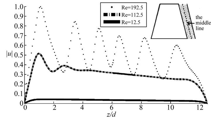 (b)
(b)
Figure 2. (a) and (b) separately illustrate the distribution of pressure and velocity along the middle line marked in the same figure for  and
and
 where
where .
.
 (a) (b) (c)
Figure 3. Front view of streamlines of the flow for  and
and , (a) at Re = 12.5 Taylor vortex is not formed; (b) at Re = 112.5 the first Taylor vortex appears; (c) at Re = 192.5 the annulus is filled with six-pairs of vortices.
bution curve of the pressure and the velocity near the bottom end plate (see: Figure 2 and Figure 3(b)). From Figure 3(c) we see that the gap is filled with six-pairs of vortices at about , in this case the whole distribution curves of the pressure and the velocity are fluctuant.
6. Conclusions and Discussion
In this work dimensional and mechanical similarity analysis for the flow in rotating liquid film reactor (RLFR) are presented. It is proved that at each point of the flow field the dimensionless quantity of pressure and velocity is completely determined by parameters:  and
and . Moreover, between RLFR and a manufacturing equipment geometrically similar to RLFR, a necessary condition and a sufficient condition for mechanical similarity are derived. Finally, as examples, numerical simulation for some parameters is implemented. The distribution of pressure for
  in Figure 2(a) looks like a horizontal straight line, the actual calculation result is not the case. The reason is that the pressure amplitude for
  is much larger than the one for
  and the pressure in this figure is nondimensionalized by the largest pressure.
In [3] it is showed that increasing the speed of the rotor  in the RLFR or increasing the rotor-stator gap
  resulted in a decrease in particle size and narrower particle size distribution. The experiment in [3] also suggested that the turbulence had big effect on particle size and particle size distribution. The turbulent effects were directly related to
  and
and . There was no discussion on the effects of parameters
  and
and .
.
The results in this paper imply that the particle size and the particle size distribution depend not only on  and
and  (included in
 ) but also on parameters
  and
and . How the particle size and particle size distribution depend on
  and
and  is an interesting problem which is worth studying both experimentally and numerically. Moreover, our analysis reveals that
  and
and  are not independent, they may substitute each other, at least from qualitative point of view. This assertion requires experimental verification.
The results obtained in this paper provide a theoretical basis for further study of the reactor by experiment and numerical simulation.
REFERENCES
- G. I. Taylor, “Stability of a Viscous Liquid Contained between Two Rotating Cylinders,” Philosophical Transactions Royal Society of London, Vol. 223, No. 605-615, 1923, pp. 289-343. doi:10.1098/rsta.1923.0008
- S. Dong, “Direct Numerical Simulation of Turbulent Taylor-Couette Flow,” Journal of Fluid Mechanics, Vol. 587, 2007, pp. 373-393. doi:10.1017/S0022112007007367
- S. C. Guo, D. G. Evans, D. Q. Li and X. Duan, “Experimental and Numerical Investigation of the Precipitation of Barium Salfate in a Rotating Liquid Film Reactor,” AIChE Journal, Vol. 55, No. 8, 2009, pp. 2024-2034. doi:10.1002/aic.11818
- M. Wimmer, “An Experimental Investigation of Taylor Vortex Flow between Conical Cylinders,” Journal of Fluid Mechanics, Vol. 292, 1995, pp. 205-227. doi:10.1017/S0022112095001492
- M. Wimmer, “Taylor Vortices at Different Geometries,” Physics of Rotating Fluids, Vol. 549, 2000, pp. 194-212. doi:10.1007/3-540-45549-3_12
- M. N. Noui-Mehidi, N. Ohmura, K. Nishiyama and K. Takigawa, “Effect of Wall Alignment in a Very Short Rotating Annulus,” Communications in Nonlinear Science and Numerical Simulation, Vol. 14, No. 2, 2009, pp. 613-621. doi:10.1016/j.cnsns.2007.10.004
- M. N. Noui-Mehidi, N. Ohmura and K. Kataoka, “Dynamics of the Helical Flow between Rotating Conical Cylinders,” Journal of Fluids and Structures, Vol. 20, No. 3, 2005, pp. 331-344. doi:10.1016/j.jfluidstructs.2004.12.001
- X. F. Xu and L. X. Xu, “A Numerical Simulation of Flow between Two Rotating Coaxial Frustum Cones,” Communications in Nonlinear Science and Numerical Simulation, Vol. 14, No. 6, 2009, pp. 2670-2676. doi:10.1016/j.cnsns.2008.08.019
- X. F. Xu, P. Wen, L. X. Xu and D. P. Cao, “Occurrence of Taylor Vortices in the Flow between Two Rotating Conical Cylinders,” Communications in Nonlinear Science and Numerical Simulation, Vol. 15, No. 5, 2010, pp. 1228-1239. doi:10.1016/j.cnsns.2009.05.061
- Q. S. Li, P. Wen and L. X. Xu, “Transition to Taylor Vortex Flow between Rotating Conical Cylinders,” Journal of Hydrodynamics, Vol. 22, No. 2, 2010, pp. 241- 245. doi:10.1016/S1001-6058(09)60050-0