Modeling and Numerical Simulation of Material Science
Vol. 3 No. 3 (2013) , Article ID: 33825 , 8 pages DOI:10.4236/mnsms.2013.33009
Pressurization System in Low Pressure Tube Hydroforming
Mechanical Engineering Department, The Pennsylvania State University, Erie, USA
Email: chetan.nikhare@gmail.com
Copyright © 2013 Chetan Nikhare. This is an open access article distributed under the Creative Commons Attribution License, which permits unrestricted use, distribution, and reproduction in any medium, provided the original work is properly cited.
Received January 30, 2013; revised March 1, 2013; accepted March 10, 2013
Keywords: Pressure; Low Pressure Tube Hydroforming; Ramp Pressure; Constant Pressure; Advanced High Strength Steels
ABSTRACT
Advanced high strength steels are the group of material with high strength and good formability, because high strength lesser gauge thickness can be used without compromising the function of component. In terms of economic forming process, hydroforming is the manufacturing option which uses a fluid medium to form a component by using high internal pressure. This process gained steep interest in the automotive and aerospace industries because of its many advantages such as part consolidation, good quality of the formed part etc. The main advantage is that the uniform pressure can be transferred to whole projected part at the same time. Low pressure tube hydroforming considered an inexpensive option for forming these advanced high strength steel. This paper investigates the pressurization system used during the low pressure tube hydroforming cycle. It is observed that the usage of ramp pressure cycle during forming the part from low pressure tube hydroforming results in lesser die holding force. Also, the stress, strain and thickness distribution of the part during low pressure tube hydroforming are critically analysed.
1. Introduction
Stamping industries aim to minimize the costs and optimize of its products concerning weight, strength characteristics and rigidity. Seeking for alternative production a process, hydroforming—the manufacture of hollow bodies with complex geometries by means of fluid pressure—has been shown to offer an interesting technical and economic potential to sheet metal manufacturers. The achievement of beneficial component characteristics using this process is only possible where component and process configurations are selected by considering the overall system design [1]. Hydroforming technology can achieve weight reduction of about 30% in comparison to conventionally manufactured components [2]. At the least, reducing masses improves the fuel consumption.
Hydroforming is coming as an effective manufacturing process, because it can be applied to the manufacturing of complex structural components into a single body with high structural stiffness. Tube hydroforming has been successfully developed in industry such as in the manufacturing of the components of automotive vehicles [3]. In fact tube hydroforming is called as a soft-punch forming technology [4]. Steel tube has excellent strength to weight ratio and therefore its applications can effectively reduce vehicle weight and improve vehicle stiffness. Other potential advantages are improved dimensional control and reduced cost, both of which are partially due to part consolidation and a large reduction in the welding of stampings to create closed sections [5].
Apart from many advantages, hydroforming has a main disadvantage that it requires high capacity mechanical press and high pressurization system. There are three pressurization systems which are used commonly for hydroformed products. In low pressure hydroforming, pressure specified below 83 MPa, hydroformed section length of line stays almost the same as the circumference of the blank tube. This process is mostly like tube crushing. The range of the pressures used in high pressure hydroforming is generally 83 MPa to 414 MPa. Higher pressures allow the hydroformed section length of line to be expanded up to the limit allowed by material’s plastic elongation. Any surface deformation or wrinkles, which can occur during the die closing stage, is pressed out under the high pressures. Multipressure hydroforming process with calibration pressures in the range of 69 to 173 MPa appears to be suitable for most automotive chassis and body structure applications. These pressures also achieve good quality pierced holes. This process is popularly known as pressure sequence hydroforming [6].
Several researches focused on the improvement of the quality of product by applying different pressurization system. Occurrence of local thinning and wrinkling was prevented by oscillating the internal pressure in the pulsating hydroforming. Because of oscillations of internal pressure, a uniform expansion in the bulging region was obtained, and thus the formability was improved by preventing the local thinning [7]. Biaxial test was used for calibrating and validating numerical material and friction models. At instability no additional pressure is required to increase the radius of tube [8]. Nikhare and Narasimhan [9,10] numerically evaluated that the forming limit strains during tube hydroforming is higher than the conventional stamping process and as the prestrain of tube increases, limit strain decreases, with the application of high pressure. Asnafi and Skogsgardh [11] proposed stroke controlled hydroforming and forming limit curve of tube material by experiment and simulation. Jain and Wang [12] offered dual pressure tube hydroforming process in which the plastic instability is delayed and the ductility of the metal is increased. Smith, Ganeshmurthy and Alladi [13] presented tube hydroforming double-sided high pressure (DSHP) boundary condition which increased formability relative to that observed for the traditional single-sided high pressure (SSHP).
The concept of sequenced forming pressure is proposed to reduce the thickness variation of the product and the forming pressure [14]. The maximum internal pressure and maximum crushing force needed in the crushing processes combined with preforming and hydroforming are only about 5% and 7%, respectively, of those in the expansion test. Also, the thickness distributions of the formed products obtained by the crushing processes are much more uniform than those by the hydraulic expansion test [15]. The internal pressure and crushing force needed for the crushing processes are only about 1/40 and 1/27 than that of expansion process in regular triangular die [16]. Similar study performed by Nikhare et al. [17,18] on the simple square shape geometry during low pressure tube hydroforming and found that only 6% of internal pressure and almost 50% of die closing force was enough to form the component than the high pressure tube hydroforming [19]. Admittedly plastic flow pattern and thickness distribution of the tube had been studied; however comparison of different pressurization system during low pressure tube hydroforming is not yet performed. Also effect of different pressurization system on stress, strain and thickness distribution during low pressure tube hydroforming process is the part of research question.
In this paper, ramp and constant pressure are applied during low pressure tube hydroforming. Ramp pressure is allowed to linearly vary to the desired pressure with respect to time until the tube is completely formed. Constant pressure is constant to a desired pressure through out the process until the tube forms completely. Comparison of ramp and constant pressure during low pressure tube hydroforming process is done. Die closing force required to form the tube is predicted. Stress, strain and thickness distribution are also analysed.
2. Material and Methodology
2.1. Material
The steel investigated during simulation of low pressure tube hydroforming was a 2 mm thick commercial TRIP (780 grade). The true stress strain curve used for simulation is shown in Figure 1 and the mechanical properties are in Table 1.
2.2. Methodology
The methodology adopted to investigate the difference between ramp and constant pressurization system, low pressure tube hydroforming with square and round corner die was modelled. The die filling conditions in both the cases were analysed. The die closing force, stress and thickness distribution were compared for both processes.
2.2.1. Low Pressure Tube Hydroforming
In low pressure tube hydroforming, a tube is formed into the desired shape using low fluid pressure. For this, the tube is placed between the upper and lower die. During forming the lower die is fixed; while the upper die moves down and forms the pressurized tube into the desired shape. A schematic view of the low pressure hydroforming process is shown in Figure 2.

Figure 1. True stress-strain curve determined in tensile tests for TRIP steel.

Figure 2. Preform tube and start of low pressure tube hydroforming.

Table 1. Mechanical properties of TRIP steel.
In this process, the hydroformed section length of line stays approximately the same as the circumference of the undeformed tube. Thus the perimeter of outer un-deformed tube must be same as that of the inner perimeter of the die (Equation (1)) [19].
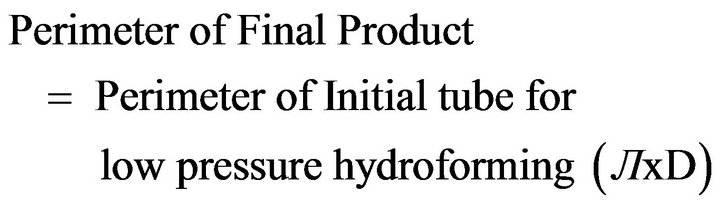 (1)
(1)
1) Square corner die low pressure tube hydroforming The square corner dies were used in this part of the study. The outer diameter of the tube was 50 mm with 2 mm gauge thickness. The inner width of the die was taken as 50 mm to fit the tube before forming. According to the perimeter calculation (Equation (1)) the height of the final part was 28.5 mm. Thus the upper die has to move 21.5 mm down to form the tube.
2) Round corner die low pressure tube hydroforming The round corner dies were used in this part. The geometry of the tube was same as in previous case. The corner radius of die was considered as 6 mm. Therefore from the perimeter calculation the height of the final part was 32.66 mm. Thus the upper die has to make a stroke of 17.34 mm down to form the tube.
2.2.2. Numerical Modelling
The tube was assumed to be a circular cylinder for simulation. Variations of wall thickness and material property parameters around the circumference of the tube were neglected. The wall thickness of the tube was taken to be the average measured value of 2 mm and cylindrical length is considered as 1mm. The stress-strain data was used to develop a constitutive model according to the flow equation, σ = Kεn.
The FE code ABAQUS/Explicit 6.5-1 version was used for the simulation of low pressure tube hydroforming. The dies were considered as a rigid body while tube was a deformable body (Figure 3). CPE4R 4-node bilinear plane strain quadrilateral elements were used. The approximate element size for the tube was 1mm with a curvature control of 0.1 and there were two layers of elements in the thickness direction. The interaction between die and tube was surface to surface tangential contact with coefficient of friction of 0.1. Radial expansion and compression was allowed.
Internal pressure and upper die travel were applied simultaneously. Four types of internal pressure curves were used for low pressure tube hydroforming as shown in Figures 4 and 5. The calculated results, for all end conditions considered, are symmetrical to the mid-section of the tube.
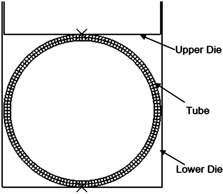
Figure 3. Low pressure tube hydroforming model.
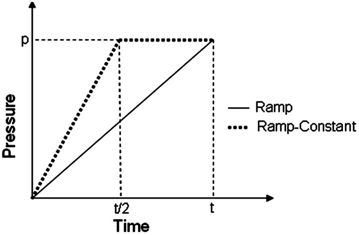
Figure 4. Ramp and Ramp-Constant pressure curves for low pressure tube hydroforming.
3. Results and Discussion
Figure 6 shows the simulation results of low pressure tube hydroforming for square corner die with ramp pressure curve. With unpressurized condition the tubes buckle which couldn’t be recovered. However, with the pressure of 5 and 10 MPa tube buckling was in recoverable state. The tube takes the complete shape of die with the application of 15 MPa of internal pressure. Further increase in pressure, reduces the corner radius of the tube; but the reduction was not significant with respect to internal pressure and die closing force. Figure 7 explains the direction of prediction of stress, strain and thickness distribution for the symmetric halve tube.
As the pressure increases, stress, strain and bending moment at the upper part, lower part, side wall and two corners of tube are continuously increases which are clear from Figures 8 and 9. Stress, strain and bending moment (Figure 10) in the upper corner is more than in the lower corner for internal pressure of 15 MPa. The upper die moves down to form the tube and bending is generated first in the upper corner. Thus the bending in the upper corner is the combine effect of punch force, material feeding and the internal pressure. But the bending in the lower corner is only because of slight material feed plus the internal pressure.
The two corners are thickening than the other sections of the tube as shown in Figure 11. The upper corner is

Figure 5. Constant and Constant-Ramp pressure curves for low pressure tube hydroforming.
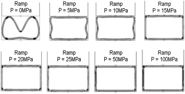
Figure 6. Formed tubes from 0 to 100 MPa with Ramp pressure curve.

Figure 7. Formed halve tube giving the direction for prediction of stress, strain and thickness.
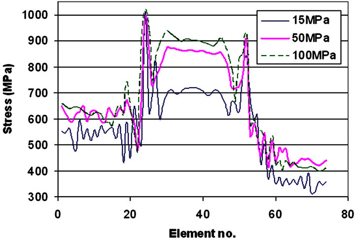
Figure 8. Halve tube stress distribution for 15, 50 and 100 MPa with Ramp pressure curve.
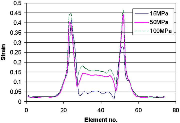
Figure 9. Halve tube strain distribution for 15, 50 and 100 MPa with Ramp pressure curve.
thickening more than the lower corner due to more materials feed in the upper corner than the lower corner. The side wall is also thickening with increase in pressure. As the pressure increases the upper and lower wall is thins and feeds the material towards the corners and side wall. For 50 and 100 MPa the upper and lower part is thinning, but for 15 MPa, the whole tube almost thickening. All graphs concluding the same remarks that 15 MPa is the best internal pressure for the given geometry, and further increase in the internal pressure seems unnecessary. Figure 12 shows the holding force required at different pressure. The die closing force is quadratically proportional with respect to the internal pressure as the pro-

Figure 10. Halve tube bending moment distribution for 15, 50 and 100 MPa with Ramp pressure curve.

Figure 11. Halve tube thickness distribution for 15, 50 and 100 MPa with Ramp pressure curve.
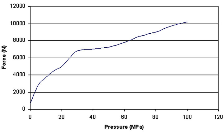
Figure 12. Force vs. pressure during low pressure tube hydroforming with Ramp pressure curve.
jected area during deformation increased continuously and that increases the force suddenly at initial stage.
Figure 13 shows the simulation results of low pressure tube hydroforming for square corner die with ramp and constant pressure curve. The corner and wall filling conditions are almost same for the ramp and constant pressure curve, but the stress, strain and bending moment distribution for the ramp pressure curve is lower than that of constant pressure curve, shown in Figures 14-16. Figure 17 shows that the tube upper part, lower part and side wall are thickening uniformly, while the two corners are thickening more; but this is not the case with constant pressure curve, the tube upper and lower part is thinning while the side wall is thickening slightly and two corners are thickening more. In constant pressure curve, pressure first developed suddenly and later it is constant throughout the process. So, the work done is instant in constant pressure curve while it is linear in ramp. For 15 MPa of internal ramp pressure curve the die closing force required more than the constant pressure curve, shown in Figure 18.
Figure 19 shows the simulation results of low pressure tube hydroforming for round corner die with ramp, con-
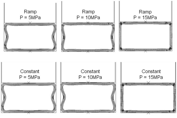
Figure 13. Ramp and Constant pressure curve low pressure tube hydroforming comparison for 5, 10 and 15 MPa with square corner die.

Figure 14. Halve tube stress distribution for 15 MPa with Ramp and Constant pressure curve with square corner die.
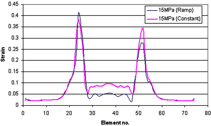
Figure 15. Halve tube strain distribution for 15 MPa with Ramp and Constant pressure curve with square corner die.

Figure 16. Halve tube bending moment distribution for 15 MPa with Ramp and Constant pressure curve with square corner die.
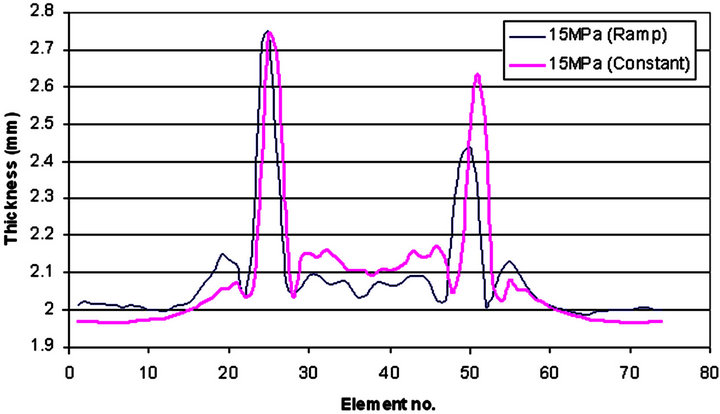
Figure 17. Halve tube thickness distribution for 15 MPa with Ramp and Constant pressure curve with square corner die.
stant, ramp-constant and constant-ramp pressure curve. With 5 and 10 MPa the corners and walls are not filling completely (region in eclipse) while with 15 MPa the tube takes the complete shape in all the pressure curve cases.
From Figures 20-22, it is clear that the end pressure
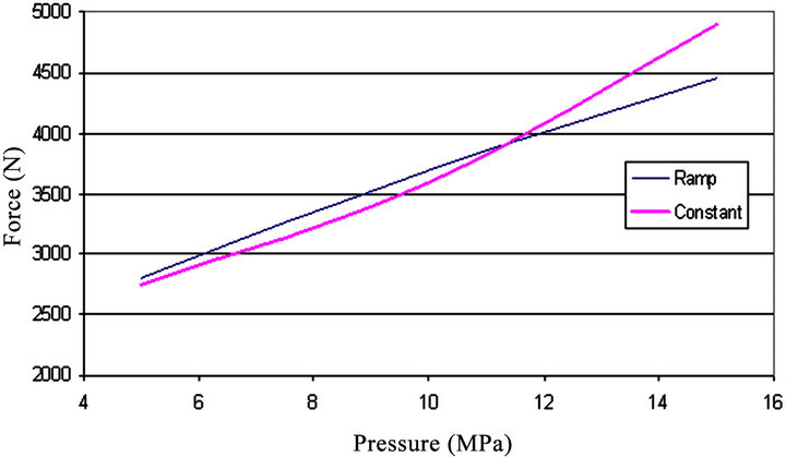
Figure 18. Force vs. pressure for Ramp and Constant pressure curve with square corner die.
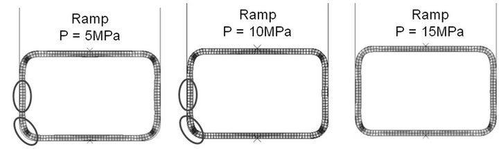

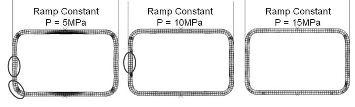

Figure 19. Ramp, Constant, Ramp-Constant and ConstantRamp pressure curve low pressure tube hydroforming comparison for 5, 10 and 15 MPa with round corner die.
curve is dominating. With pressure curves of ramp and constant-ramp the stress, strain and bending moment distribution is almost same and with pressure curves of constant and ramp-constant the stress strain distribution is similar. With the round corner dies the stress, strain and bending moment, in the upper corner is less than in lower corner, which is opposite case with the square corner die as observed earlier. From the thickness distribution, shown in Figure 23, it is observed that the tube is thinning more in case of constant and ramp-constant pressure curves.
The die closing force required with ramp and con-

Figure 20. Halve tube stress distribution for 15 MPa with Ramp, Constant, Ramp-Constant and Constant-Ramp pressure curve with round corner die.

Figure 21. Halve tube strain distribution for 15 MPa with Ramp, Constant, Ramp-Constant and Constant-Ramp pressure curve with round corner die.
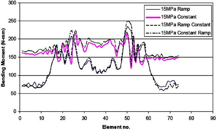
Figure 22. Halve tube bending moment distribution for 15 MPa with Ramp, Constant, Ramp-Constant and ConstantRamp pressure curve with round corner die.
stant-ramp is much lower than the constant and rampconstant pressure curves (Figure 24). So the ramp or constant-ramp curve must be the best option. Whereas, it has been aforementioned that the end pressure curve was the dominating factor, thus ramp pressure curve would be the better option to form the part with less thinning and die closing force.
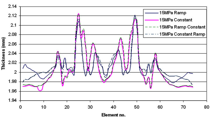
Figure 23. Halve tube thickness distribution for 15 MPa with Ramp, Constant, Ramp-Constant and Constant-Ramp pressure curve with round corner die.
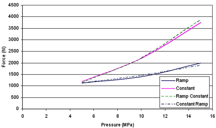
Figure 24. Force vs. pressure for Ramp, Constant, RampConstant and Constant-Ramp pressure curve with round corner die.
4. Conclusion
Low pressure tube hydroforming for the square and round die corner is studied. Different simulations with pressure curves such as ramp, constant, ramp-constant and constant-ramp during low pressure tube hydroforming are performed. With round die corner the buckling is avoided completely. Comparisons of internal pressure, die closing force, stress, strain and thickness of tube for different pressure curves are analysed. The stress and strain in the upper corner of the tube are more than in the lower corner with the square corner dies, which are the opposite case with round corner dies. The tube is thickening more in the upper corner than in the lower corner. With the ramp pressure curve the die closing force required much less and forming is smoothly done with completely filling the side walls and corners. So the ramp pressure would be the better option to form the tube during low pressure tube hydroforming.
5. Acknowledgement
The author would like to extend his gratitude to Professor Peter D. Hodgson for support and Deakin University for providing the facility to carry out this research work.
REFERENCES
- Schuler, “Metal Forming Handbook,” Springer-Verlag, Berlin, 1998, p. 405.
- H. C. Lucke, C. Hartl and T. Abbey, “Hydroforming,” Journal of Materials Processing Technology, Vol. 115, No. 1, 2001, pp. 87-91. doi:10.1016/S0924-0136(01)00774-9
- T. J. Kim, D. Y. Yang and S. S. Han, “Numerical Modelling of the Multi-Stage Sheet Pair Hydroforming Process,” Journal of Materials Processing Technology, Vol. 151, No. 1-3, 2004, pp. 48-53. doi:10.1016/j.jmatprotec.2004.04.124
- F. Dohmann and C. Hartl, “Tube Hydroforming—Research and Practical Application,” Journal of Materials Processing Technology, Vol. 71, No. 1, 1997, pp. 174- 186. doi:10.1016/S0924-0136(97)00166-0
- K. K. Chen, R. J. Soldaat and R. M. Moses, “Free Expansion Bulge Testing of Tubes for Automotive Hydroform Applications,” SAE Technical Paper Series, 2004-01- 0832.
- H. Singh, “Fundamentals of Hydroforming,” Association for Forming and Fabricating Technologies of the Society of Manufacturing Engineers, Michigan, 2003.
- K. Mori, T. Maeno and S. Maki, “Mechanism of Improvement of Formability in Pulsating Hydroforming of Tubes,” International Journal of Machine Tools and Manufacture, Vol. 47, No. 6, 2007, pp. 978-984. doi:10.1016/j.ijmachtools.2006.07.006
- M. Jansson, L. Nilsson and K. Simonsson, “The Use of Biaxial Test Data in the Validation of Constitutive Descriptions for Tube Hydroforming Applications,” Journal of Materials Processing Technology, Vol. 184, No. 1-3, 2007, pp. 69-76. doi:10.1016/j.jmatprotec.2006.09.039
- C. Nikhare and K. Narasimhan, “Limit Strains Comparison during Tube and Sheet Hydroforming and Sheet Stamping Processes by Numerical Simulation,” Computers, Materials, & Continua, Vol. 7 No. 1, 2008, pp. 1-8.
- C. Nikhare and K. Narasimhan, “Effect of Prestrain on Formability and Forming Limit Strains during Tube Hydroforming,” Computers, Materials, & Continua, Vol. 7 No. 3, 2008, pp. 129-138.
- N. Asnafi and A. Skogsgardh, “Theoretical and Experimental Analysis of Stroke-Controlled Tube Hydroforming,” Materials Science and Engineering A, Vol. 279, No. 1-2 , 2000, pp. 95-110. doi:10.1016/S0921-5093(99)00646-2
- N. Jain and J. Wang, “Plastic Instability in Dual-Pressure Tube-Hydroforming Process,” International Journal of Mechanical Sciences, Vol. 47, No. 12, 2005, pp. 1827- 1837. doi:10.1016/j.ijmecsci.2005.07.010
- L. M. Smith, S. Ganeshmurthy and K. Alladi, “DoubleSided High-Pressure Tubular Hydroforming,” Journal of Materials Processing Technology, Vol. 142, No. 3, 2003, pp. 599-608. doi:10.1016/S0924-0136(02)01041-5
- M. Mason, “Tube Hydroforming Using Sequenced Forming Pressures,” Proceedings of the International Seminar on Report Status and Trend of Tube Hydroforming, Tokyo, 1999, pp. 80-98.
- Y. M. Hwang and T. Altan, “Finite Element Analyses of Tube Hydroforming Processes in a Rectangular Die,” Finite Elements in Analysis and Design, Vol. 39, No. 11, 2003, pp. 1071-1082. doi:10.1016/S0168-874X(02)00157-9
- Y. M. Hwang and T. Altan, “FE Simulation of the Crushing of Circular Tubes in Triangular Cross-Sections,” Journal of Materials Processing Technology, Vol. 125- 126, 2002, pp. 833-838. doi:10.1016/S0924-0136(02)00385-0
- C. Nikhare, M. Weiss and P. D. Hodgson, “Numerical Investigation of High and Low Pressure Tube Hydroforming,” Proceedings of Numisheet, Switzerland, 2008, pp. 691-696.
- C. Nikhare, M. Weiss and P. D. Hodgson, “Experimental and Numerical Investigation of Low Pressure Tube Hydroforming on Stainless Steel,” Steel Research International, Krakow, 21-24 September 2008, pp. 272-279.
- C. Nikhare, M. Weiss and P. D. Hodgson, “FEA Comparison of High and Low Pressure Tube Hydroforming of TRIP Steel,” Computational Materials Science, Vol. 47, No. 1, 2009, pp. 146-152. doi:10.1016/j.commatsci.2009.06.024