Open Journal of Medical Imaging
Vol.2 No.4(2012), Article ID:25322,6 pages DOI:10.4236/ojmi.2012.24022
Inhibition of the Oversensing of Cardiac Pacemakers in Chest CT
1Department of Radiology, National Hospital Organization Tokyo Medical Center, Tokyo, Japan
2Department of Clinical Engineering, National Hospital Organization Tokyo Medical Center, Tokyo, Japan
3Department of Radiological Technology, Nihon Institute of Medical Science, Moroyama, Japan
4Toshiba Medical Systems Corporation, Tokyo, Japan
5Department of Radiology, Japanese Red Cross Medical Center, Tokyo, Japan
6Graduate Division of Medical Health Sciences in Graduate School of Komazawa University, Tokyo, Japan
Email: *myhp.na@water.ocn.ne.jp
Received August 12, 2012; revised September 23, 2012; accepted October 5, 2012
Keywords: Cardiac Pacemaker; Refractory Period; Oversensing; Computed Tomography; Chest CT
ABSTRACT
Objectives: The purpose of this study is to identify how to manage oversensing of pacemakers in chest CT. Methods: Four different models of pacemakers were examined to select the pacemaker generating oversensing. To the pacemaker with oversensing, intermittent switching X-ray was exposed using ECG-gated CT helical scan system at prospective CTA mode. IVY Model was used to synchronize the ECG. Only during in the alert period that is non-refractory and sensing is available, intermittent switching X-ray (300 msec/sec) was exposed in chest CT. For comparison, the same intermittent switching X-ray (300 msec/sec) was exposed in the refractory period when sensing was not available. Results: Oversensing was detected only in one of the four pacemakers tested. In this pacemaker, oversensing was generated by exposure of the intermittent switching X-ray in the alert (non-refractory) period, but oversensing was not observed in the refractory period. Conclusion: A pacemaker has alert and refractory periods. Oversensing of a pacemaker was found to be inhibited by selective ECG-synchronized exposure in the refractory period. Since all pacemakers have the refractory period, the results of this study can be widely applied to the patients with pacemakers in chest CT, and their chest CT can be operated safely.
1. Introduction
In 2005, the first case of the pacemaker-related defect was reported in Japan claiming that a pacemaker induced a partial electric oversensing in X-ray CT [1-8,11,12]. Ministry of Health, Labor and Welfare issued the reminder to medical institutions titling “Precautions for the use of X-ray CT and implantable cardiac pacemakers with regard to their interactions” [11,12].
In 2009, the precautions were revised [13], and recommended to monitor pulses at the fixed pacing mode or to stop X-ray irradiation in the patient with a pacemaker because X-ray irradiation temporarily suppresses the pacing, and may induce bradyarrhythmia with dizziness or fainting.
As of 2011, the reports of oversensing and reset of the cardiac pacemaker still have been observed [7]. Therefore, in this article we investigated the way to inhibit the oversensing in X-ray CT.
2. Materials and Methods
CT unit (Aquilion PRIME, 80-detector row, Toshiba), four models of pacemakers (St. Jude Medical, and Medtronic) and two pacemaker programmers were used. Pacing rate and refractory period were set at 60 ppm and 300 msec, respectively. A pacemaker was attached on the subclavicular fossa of the chest phantom (Kyoto Kagaku) and was scanned by helical CT at 15.6 helical pitch (0.195 beam pitch), rotation time of 0.35 msec, and tube voltage of 120 kVp in Automatic Exposure Control mode 12 (AEC 12) used in Toshiba CT units (Figure 1).
2.1. Detection of the Oversensing of a Pacemaker
Four models of pacemakers were investigated to detect the oversensing induced by non-ECG-gated CT helical scans. The same scan parameters were used with the ones above-mentioned. The time of X-ray exposure to pacemakers was set at 2.0 sec.
2.2. Inhibition of the Oversensing of a Pacemaker
The intermittent switching X-ray was exposed to the pacemaker detected oversensing. ECG-gated CT helical scan was performed in the Prospective CTA Model in Toshiba CT units (Aquilion PRIME, Toshiba Medical Systems, Tokyo, Japan) [14]. IVY Model (Ivy Biomedical Systems, Inc.) was used for ECG synchronizationing the ECG.
In the sensible period (non-refractory period, defined as alert period), intermittent switching X-ray was exposed at 300 msec per second were to the pacemaker attached on the chest phantom. Similarly, the intermittent switching X-ray was exposed in the non-sensible period (refractory period) (Figure 2).
3. Results
3.1. Detection of the Oversensing of a Pacemaker
X-ray was irradiated to the pacemakers in CT (Figure 3). Three (models II - IV) of 4 pacemakers (II - IV) did not observe oversensing (Table 1). Both atrial pacing (AP) and ventricular pacing (VP) were normal in all three pacemakers without oversensing. In the pacemaker (model I) which showed oversensing, AP and VP were changed to atrial oversensing (AS) and ventricular oversensing (VS), respectively (Figure 4). These results show that oversensing suppressed the changes of AP and VP (AP→AS and VP→VS). The time when the pacing was blocked by oversensing was 3.8 sec. Figure 5 shows that oversensing occurred in the atrium and ventricle and that pacing rate was changed by oversensing in the range between 50 and 180 ppm.

Figure 1. Chest CT with a pacemaker.
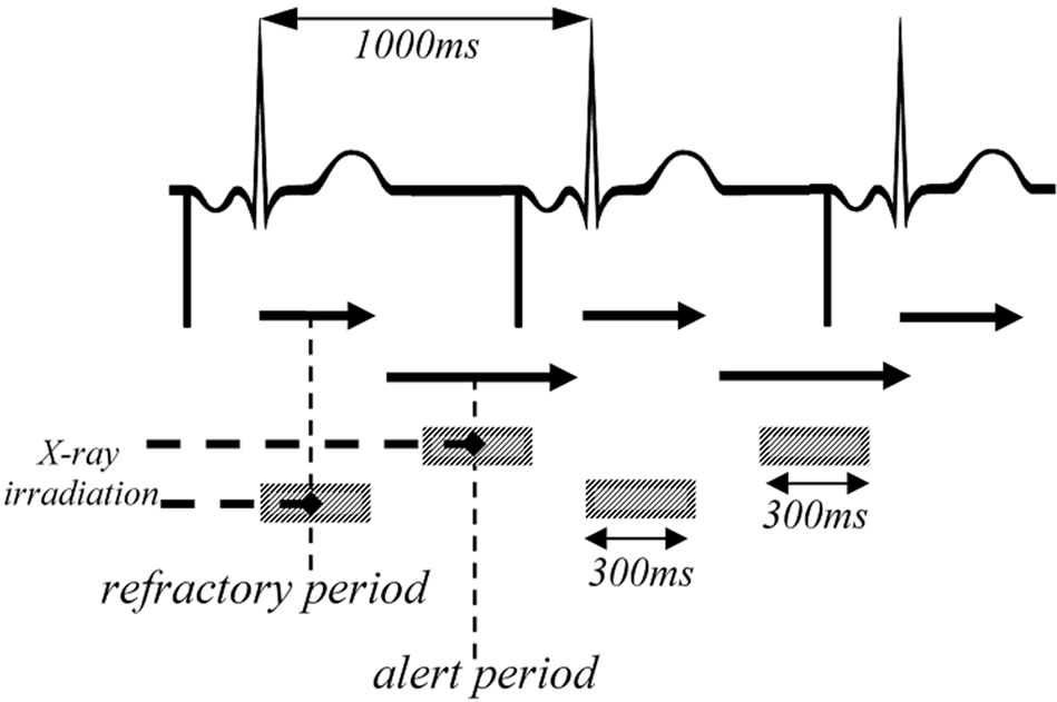
Figure 2. The image of the timing of intermittent switching exposures to the pacemaker at the interval of 60 ppm. In the sensible period defined as alert period and the non-sensible period defined as refractory period, intermittent switching X-ray was exposed at 300 ms per second in chest phantom CT.
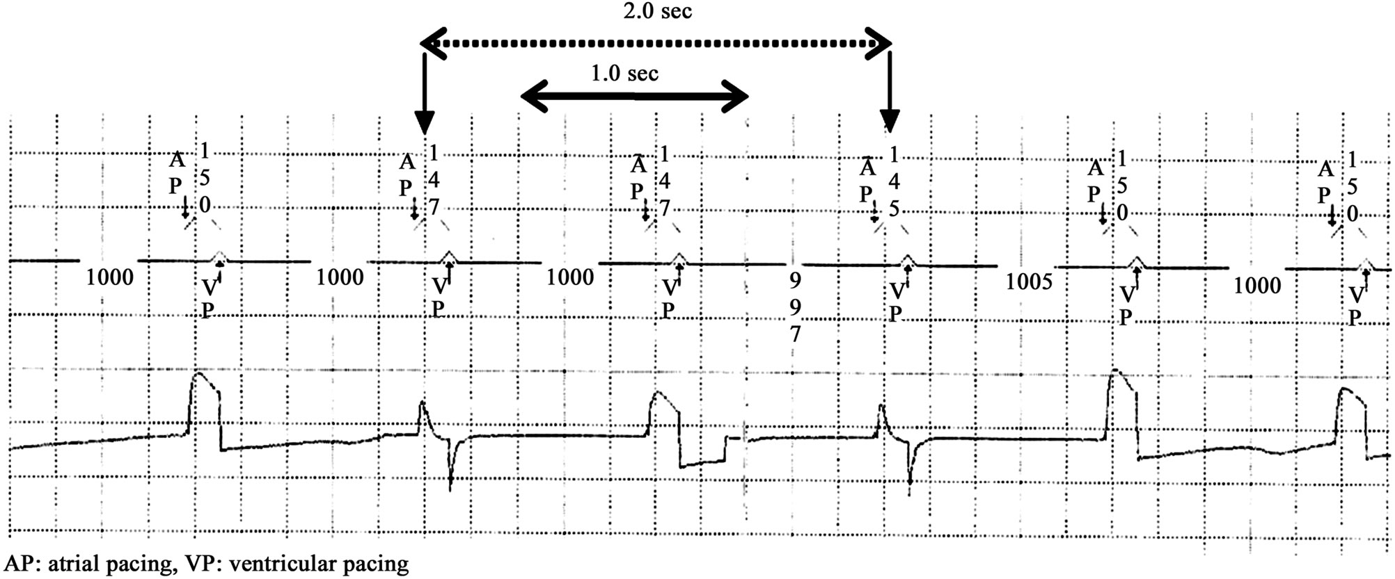
Figure 3. ECG of the pacemakers which did not show oversensing. In ECG, 3 (models II - IV) of 4 pacemakers did not show oversensing after exposure for 2.0 sec. Both atrial pacing (AP) and ventricular pacing (VP) were normal in these 3 pacemakers.
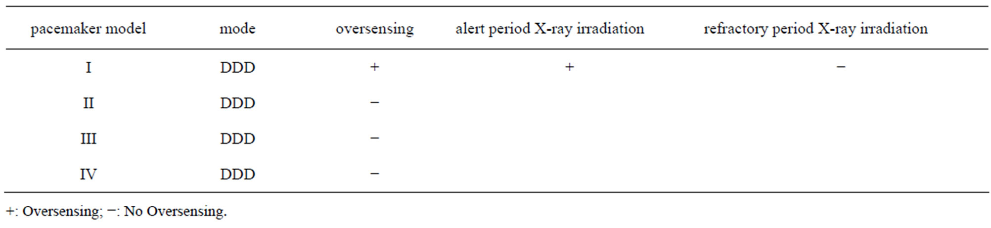
Table 1. The results of 4 pacemaker models after CT irradiation and the results of the over-sensing-positive model I in the alert and refractory periods. Three (models II-IV) of 4 pacemakers did not show oversensing. In the model I which showed oversensing, the intermittent switching exposure induced oversensing in the alert period, but not in the refractory period.
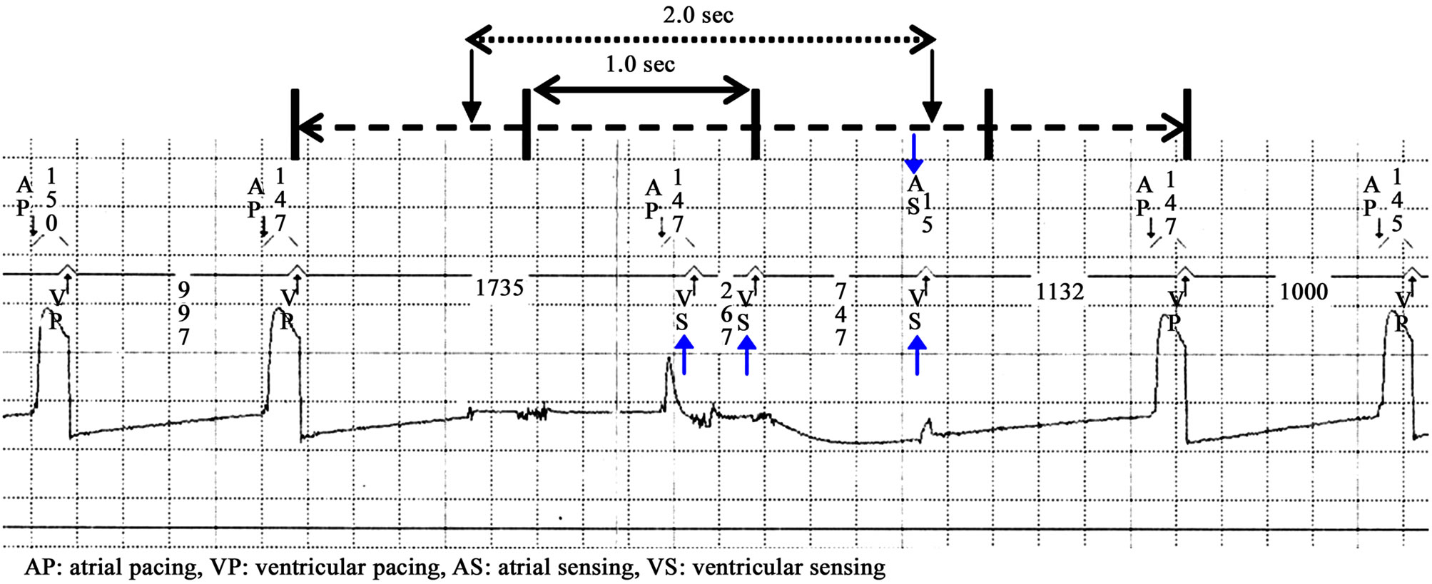
Figure 4. ECG of the pacemaker which observed oversensing. In ECG, one pacemaker (model I) showed oversensing after exposure for 2.0 sec. In this model I, atrial pacing (AP) and ventricular pacing (VP) were changed to the atrial oversensing (AS) and ventricular oversensing (VS), respectively. It is evident that oversensing suppressed the changes of AP and VP (AP→AS and VP→VS). Not-pacing time caused by oversensing was 3.8 sec.
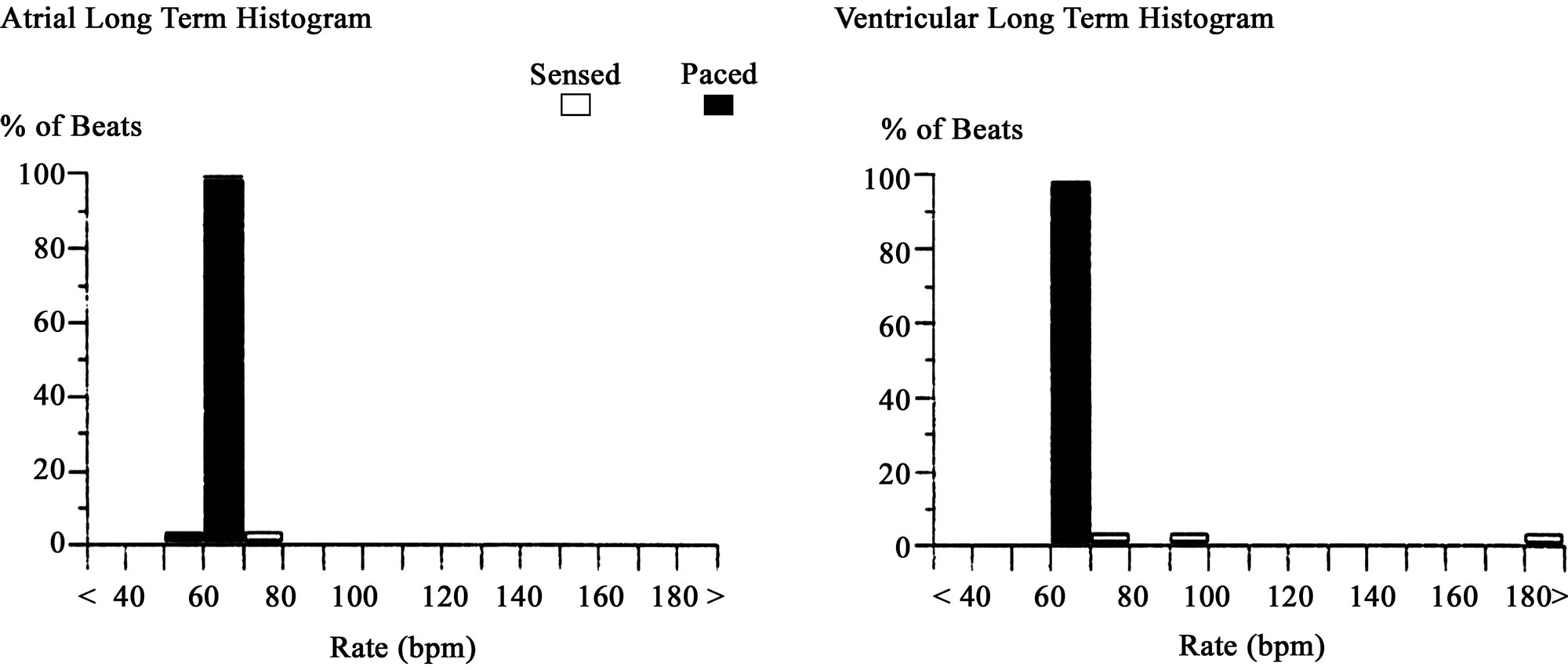
Figure 5. Atrial and ventricular long-term histograms (% of beats) of the pacemaker which observed oversensing (model I). The graphs show that oversensing occurs in the atrium and ventricle, and pacing is changed in the range between 50 and 180 ppm by oversensing.
3.2. Inhibition of the Oversensing of a Pacemaker
Figure 6 shows the results in the sensible alert period. Intermittent switching X-ray was exposed at 300 msec per second and followed chest phantom CT. ECG showed the changes from AP to AS and from VP to VS. These results show that oversensing suppressed the changes of AP and VP (AP→AS and VP→VS, arrows in Figure 6). The time when the pacing was blocked by was oversensing was 4.8 sec (Table 1, Figure 6).
Figure 7 shows the results of the non-sensable refracttory period. The intermittent switching X-ray was exposed at 300 ms per second and followed chest phantom CT. In ECG, both AP and VP were normal and no oversensing was observed (Table 1). Oversensing of the pacemaker was not induced by X-irradiation in the refractory period.
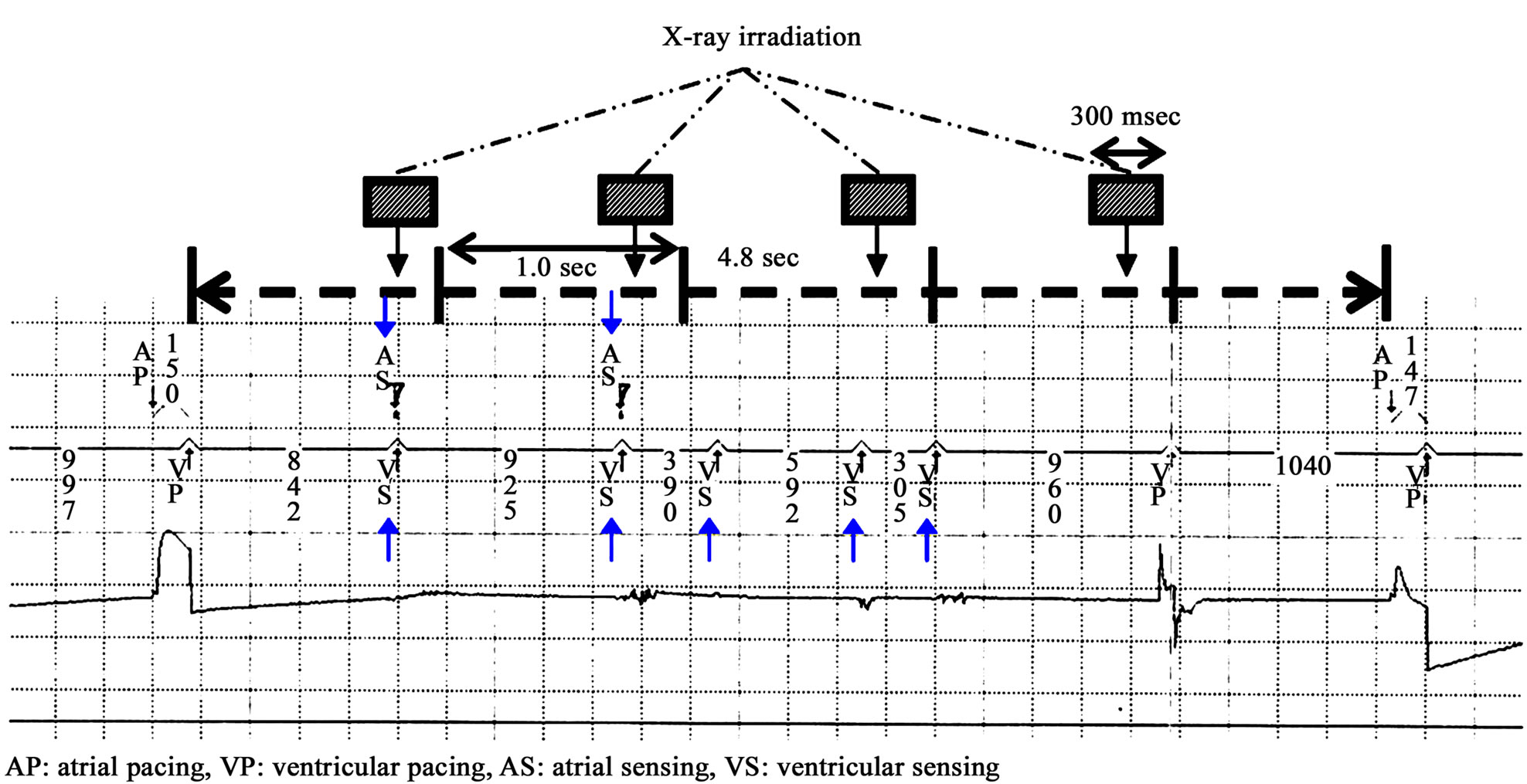
Figure 6. (model I) After selected irradiation to the oversensing-positive pacemaker in the alert period, changes from AP to AS and from VP to VS are recorded in ECG, indicating oversensing inhibits the changes of AP and VP. Not-pacing time induced by oversensing was 4.8 sec.

Figure 7. Inhibition of oversensing after irradiation in the refractory period to the oversensing-positive pacemaker (model I). After selected irradiation in the refractory period, both AP and VP were normal, which indicates oversensing was inhibited.
4. Discussion
In 2005, the first case of pacemaker-related defect was reported in Japan claiming that a pacemaker induced a partial electric oversensing in X-ray CT [1-8,12,13]. In this study, we investigated the way to inhibit the oversensing in CT. It is well known that a pacemaker has the alert and refractory periods. The alert period is defined as the time when a pacemaker is sensible, and the refractory period as the time when a pacemaker is not sensible. As shown in Figure 8, the mechanism of action of a pacemaker consists of the alert and refractory periods, and the refractory period consists of blanking period and noise sampling period. In this study, we considered that a pacemaker may recognize the energy from X-ray as a noise if X-ray is exposed at the timing when the atrial and ventricular channels immediately after ventricular pacing (VP) become post ventricular atrial blanking (PVAB) and post ventricular atrial refractory period (PVARP), respectively. As a result, oversensing of a pacemaker could be avoided almost perfectly.
The original roll of the refractory period of a pacemaker is to make them senseless to kinetic energy of preceding spontaneous pulsation in the patient with a pacemaker and to prevent the oversensing of the pacemaker. Therefore, the sensing amplifier is completely turned off in the blanking period, and is set at the time frame following pacing or the sensing event. For the same reason, the sensing amplifier is turned on in the noise sampling period, and is set at the time frame following blanking period, but the amplifier is programmed to recognize oversensing events as a noise. PVARP is consisted of the blanking period and noise sampling period. In this study, oversensing was inhibited after exposure of X-ray for 300 msec in PVARP which a pacemaker inherently has. In summary, we demonstrated that the refractory period is effective not only for inhibition of oversensing after spontaneous pulsation but also for X-ray exposure. In the alert period, a pacemaker is programmed to sense spontaneous events (if the heart beats spontaneously without pacing) and to suppress pacing. The reports of oversensing presented at academic conferences are based on the results of X-ray irradiation in the alert period [1-10]. However, we demonstrated that the oversensing of a pacemaker is not induced by X-ray irradiation in the refractory period. These findings lead us to conclude that they are quite useful to all X-ray examinations in the patients who implanted a pacemaker all the pacemakers have their own refractory period. There are 3 limitations in our study: the first is the dose rate of X-ray was not evaluated, because the oversensing occurs more frequently with increased dose rate [3,7]. The second is our suppression method of oversensing is not applicable to some CT units that are unable to do intermittent switching exposure during ECG gating. The third is the numbers of the pacemakers examined in this study are too few. These limitations should be evaluated in the future.
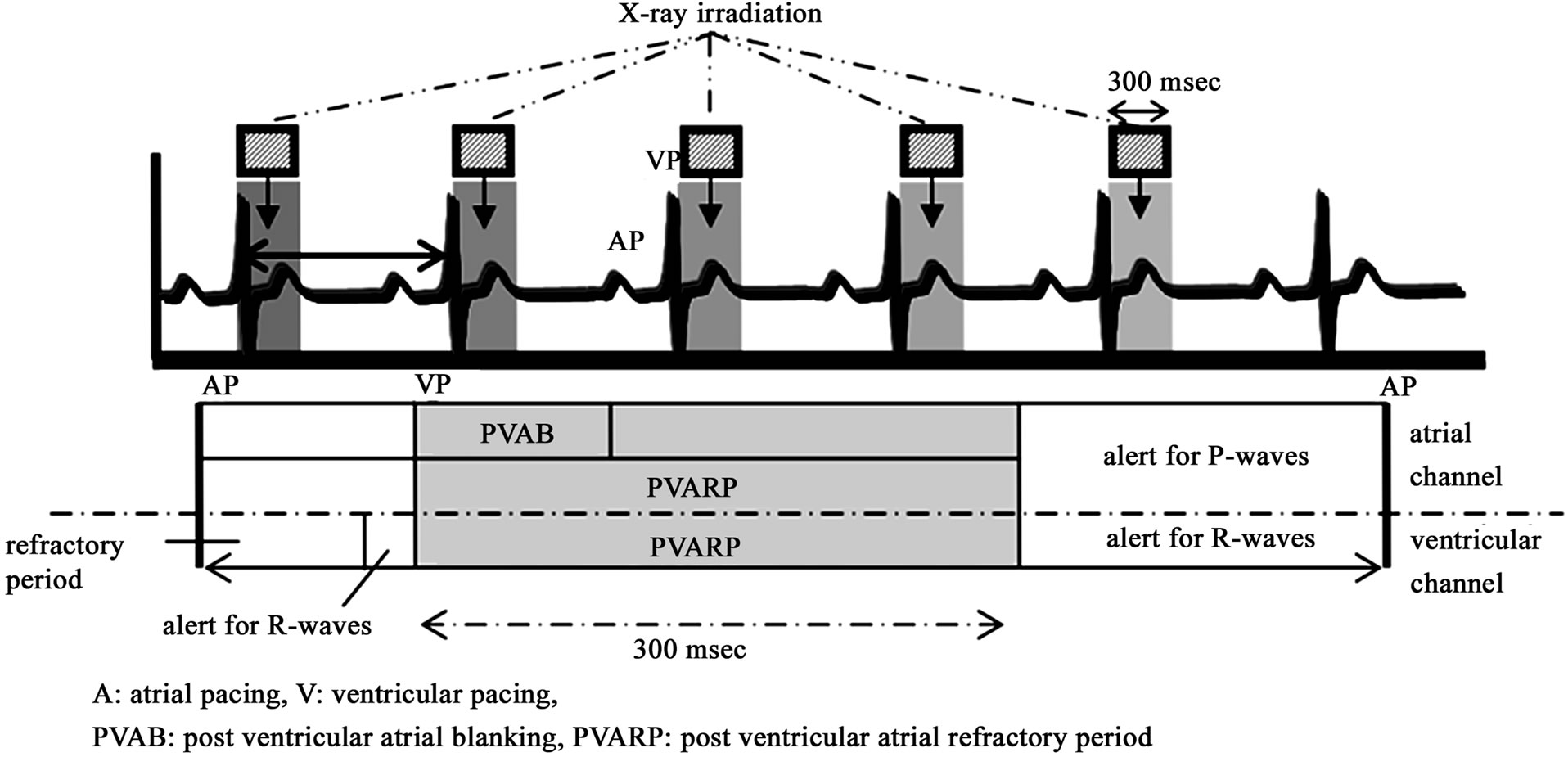
Figure 8. X-ray irradiation in the alert and refractory periods (PVAB and PVARP) to the over-sensing-positive pacemaker. A pacemaker has essentially alert and refractory periods. The alert period is defined as the sensible period, and the refractory period as the non-sensible period. The refractory period consists of blanking period and noise-sampling period. In this study, oversensing was inhibited after X-ray exposure to the pacemaker in the refractory period (PVAB, PVARP) that both atrial and ventricular channels become non-sensible immediately after VP because the pacemaker recognized the energy from X-ray as a noise.
5. Conclusion
The susceptibility of a pacemaker to X-rays differs among the different models. Pacemakers are known to have alert and refractory periods. We found that the oversensing of a pacemaker can be inhibited by exposing intermittent X-ray only in the refractory period of a pacemaker, which means that chest CT can be examined safely in the patients with cardiac pacemakers. Our results will be applied to all types of pacemakers because every pacemaker has the refractory period.
REFERENCES
- C. H. McCollough, J. Zhang, A. N. Primak, W. J. Clement and J. R. Buysman, “Effects of CT Irradiation on Implantable Cardiac Rhythm Management Devices,” Radiology, Vol. 243, No. 3, 2007, pp. 766-774. doi:10.1148/radiol.2433060993
- O. Nakamura, G. Nakaya, S. Ogashiwa, A. Hashimoto and M. Kondou, “Experimental Study of the Influence on Pacemakers of X-Rays from Angiocardiography Equipment,” Japanese Journal of Radiological Technology, Vol. 64, No. 3, 2008, pp. 335-341. doi:10.6009/jjrt.64.335
- N. Umezawa, M. Hirose and T. Shinbo, “Verification of Irradiation Conditions of X-Rays That Influence Implantable Cardiac Pacemakers,” Japanese Journal of Radiological Technology, Vol. 64, No. 7, 2008, pp. 795-804. doi:10.6009/jjrt.64.795
- N. Oda, H. Nakajima, H. Abe, S. Koyama and S. Kakeda, “Effect of Diagnostic X-Rays of Implantable Cardiac Pacemakers and Implantable Cardioverter Defibrillators, and It’s Management,” Japanese Journal of Radiological Technology, Vol. 64, No. 7, 2005, pp. 805-813. doi:10.6009/jjrt.64.805
- M. Lewis, “Radiation Dose Issues in Multi-Slice CT Scanning,” Impact Technology Update, No. 3, 2005. http://www.impactscan.org/download/msctdose.pdf
- S. Yamaji, S. Imai and F. Saito, “Does High-Power Computed Tomography Scanning Equipment Affect the Operation of Pacemakers?” Circulation Journal, Vol. 70, No. 2, 2006, pp. 190-197. doi:10.1253/circj.70.190
- T. Ushijima, Y. Yamao, N. Nagasawa, M. Matsuzuki and T. Sasou, “Partial Electrical Reset of CT Irradiation on Implantable Cardiac Devices: Relationship between Reset and Tube Voltage, Tube Current, and Rotation Time,” Japanese Journal of Radiological Technology, Vol. 67, No. 6, 2011, pp. 648-653. doi:10.6009/jjrt.67.648
- N. G. Blamires and J. Myatt, “X-Ray Effects on Pacemaker Type Circuits,” Pacing and Clinical Electrophysiology, Vol. 5, No. 2, 1982, pp. 151-155. doi:10.1111/j.1540-8159.1982.tb02206.x
- D. L. Hayes, P. J. Wang, D. W. Reynolds, M. Estes, J. L. Griffith, et al., “Interference with Cardiac Pacemakers by Cellular Telephones,” The New England Journal of Medicine, Vol. 336, No. 21, 1997, pp. 1473-1479. doi:10.1056/NEJM199705223362101
- M. Niehaus and J. Tebbenjohanns, “Electromagnetic Interference in Patients with Implanted Pacemakers or Cardioverter-Defibrillators,” Heart, Vol. 86, No. 3, 2001, pp. 246-248.
- Pharmaceuticals and Medical Devices Safety Information, No. 213, 2005, pp. 3-4. http://www.pmda.go.jp/english/index.html
- Pharmaceuticals and Medical Devices Safety Information, No. 221, 2006, pp. 12-15. http://www.pmda.go.jp/english/index.html
- Pharmaceuticals and Medical Devices Safety Information, No. 263, 2009, pp. 34-36. http://www.pmda.go.jp/english/index.html
- T. Ota, M. Tsuyuki, M. Okumura, T. Sato and T. Kondo, “Evaluation of Exposure Dose Reduction in Multislice CT Coronary Angiography (MS-CTA) with Prospective ECG-Gated Helical Scan,” Proceedings of SPIE, Vol. 6913, 2008.
NOTES
*Corresponding author.