Open Journal of Orthopedics
Vol.3 No.3(2013), Article ID:34515,5 pages DOI:10.4236/ojo.2013.33030
Three-Dimensional Computed Tomography Assessment and Planning for Severe Lower Limb Deformities: A Case Report of Bilateral Fibular Hemimelia
![]()
Department of Orthopedics, Institute of Health Biosciences, The University of Tokushima Graduate School, Tokushima, Japan.
Email: kyositeru@yahoo.co.jp
Copyright © 2013 Yoshiteru Kawasaki et al. This is an open access article distributed under the Creative Commons Attribution License, which permits unrestricted use, distribution, and reproduction in any medium, provided the original work is properly cited.
Received May 1st, 2013; revised June 1st, 2013; accepted June 13th, 2013
Keywords: Deformity Correction; Preoperative Planning; Three-Dimensional Computed Tomography; Fibular Hemimelia; Taylor Spatial Frame
ABSTRACT
To correct a lower limb deformity, orthopedic surgeons must have an exact understanding of the deformity. In general, preoperative planning is carried out using anterior-posterior (AP) and lateral radiographs. However, for severe cases with a combination of angular and rotational deformities of the lower limb, obtaining true AP and lateral radiographs is difficult and accurate calculation of the rotational deformity from radiographs is impossible. In this report, we propose to focus on preoperative assessment using three-dimensional (3D) reconstruction images of computed tomography (CT) scans for severe lower limb deformity in a patient with bilateral fibular hemimelia type II according to the AchtermanKalamchi classification. She underwent bifocal deformity corrections of the bilateral tibiae using Taylor spatial frames in combination with the Ilizarov external fixator. Complete bony union was achieved, without angular deformity or limb length discrepancy.
1. Introduction
For the assessment and correction planning of lower limb deformities, true anterior-posterior (AP) and lateral radiographs are used [1,2]. However, two-dimensional preoperative planning can lead to errors and failure to achieve optimal correction in patients with severe lower limb deformities. Furthermore, accurate calculation of the rotational deformity is impossible from radiographs. In this paper, we describe three-dimensional computed tomography (3D-CT) assessment and planning for severe lower limb deformity in a patient with bilateral fibular hemimelia type II according to the Achterman-Kalamchi classification [3]. Deformity correction and bony union were achieved using Taylor spatial frames (TSF) [4-6] in combination with the Ilizarov external fixator [7-10].
2. Case Report
A 16-year-old girl with bilateral type II fibular hemimelia according to the Achterman-Kalamchi classification [3] complained of severe valgus deformity and flexion contracture in both knees with anteromedial bowing of the tibiae. She had not been treated for the fibular hemimelia before her first visit to our hospital. A fulllength AP view standing radiograph and lateral radiographs of the limbs were taken (Figures 1(a)-(c)). Although she thought this position neutral, these radiographs were not taken in the patella forward position. The radiographs did not provide any correct assessments of the deformities.
For accurate assessment, we performed 3D-CT. Using a volume rendering technique (Aquarius Net Viewer workstation, TeraRecon, Inc., San Mateo, CA) [11,12], we were able to see by changing the rendering image to highlight skin layers, muscles and bones that her legs were externally rotated in the supine position (Figures 2(a)-(f)). On the same volume rendering workstation, we adjusted the image of her legs to adjust the patella forward (Figures 3(a) and (b)) and the femoral condyles in overlapping position (Figures 3(c) and (d)) which provided true AP and lateral images, respectively. These 3D images of her lower extremities revealed that the femurs had no deformities in normal alignment with the knees fully extended (Figure 3(e)). Knee flexion and valgus
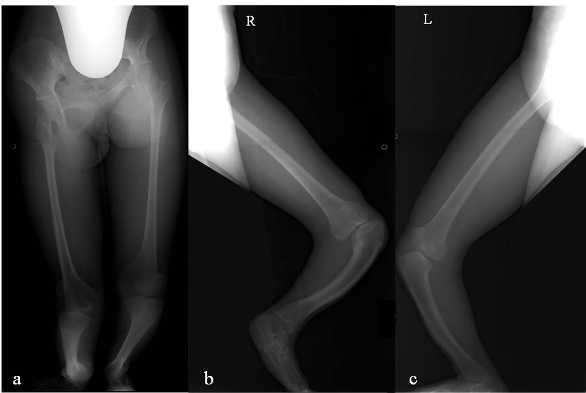
Figure 1. (a) Full-length AP view standing radiograph. (b) Long lateral view radiograph of the right leg with the knee in full extension. (c) Long lateral view radiograph of the left leg with the knee in full extension. These are not true AP or lateral radiographs.
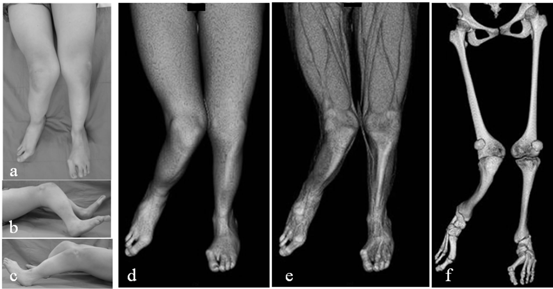
Figure 2. (a)-(c) Clinical photographs of the patient’s legs in the supine position. (d)-(f) 3D-CT images of the legs externally rotated in the supine position with highlighted skin layers, muscles, and bones.
deformity was due to tibial valgus and procurvatum just distal to the tibial tubercle. Two centers of rotation of angulation (CORAs) were identified in each tibia. The magnitude of valgus deformity in the right tibia at the proximal CORA was 60˚ and at the distal CORA was 27˚, and in the left tibia was 26˚ and 16˚, respectively. The corresponding magnitude of procurvatum deformity in the right tibia was 50˚ and 38˚ and in the left tibia was 30˚ and 11˚, respectively. For assessment of the rotation deformity, the caudo-cranial view of the lower legs (bird’s eye view) was used (Figure 3(f)). This view of the left lower leg revealed approximately 40˚ internal tibial torsion; It is difficult to accurately calculate this torsion because of severe angular deformity and deficiency of the fibula and lateral rays of the foot.
Ideally, two osteotomies would be performed at the two CORAs simultaneously (bifocal tibial osteotomy with gradual deformity correction). However, we had to choose a staged operation because of the severity of the deformities. There was not enough space on the concave
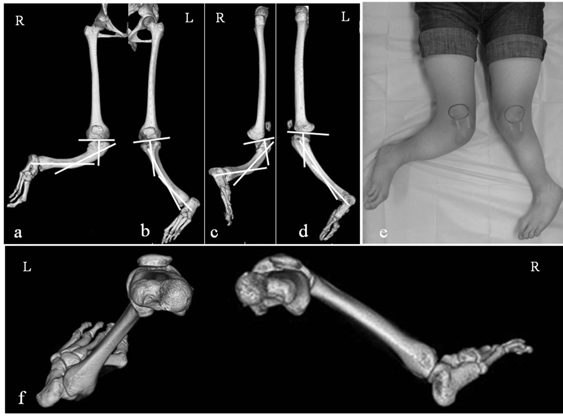
Figure 3. (a) 3D-CT image of the right leg with the patella forward (true AP) shows 60˚ valgus at the proximal CORA and 27˚ valgus at the distal CORA. (b) True AP image of the left leg shows 26˚ valgus at the proximal CORA and 16˚ valgus at the distal CORA. (c) 3D-CT image of the right leg with the femoral condyles overlapping (true lateral) shows 50˚ procurvatum at the proximal CORA and 38˚ procurvatum at the distal CORA. (d) True lateral image of the left leg shows 30˚ procurvatum at the proximal CORA and 11˚ procurvatum at the distal CORA. (e) Clinical photographs of the legs with the knee forward. (f) Bird’s eye view shows 40˚ internal torsion of the left tibia. These 3D images show that the femurs have no deformity with the knees fully extended.
posterolateral aspect of the tibia to put three external fixator rings. At the first operation, osteotomy was performed just distal to the tibial tubercle (proximal CORA) and a TSF was put on each tibia (Figures 4(a)-(h)). On the right side in which subluxation of the knee with cruciate ligament deficiency was evident, an Ilizarov ring fixator bridging the knee joint was added to prevent the further subluxation during deformity correction (Figures 4(a) and (b)).
Eighty-five days after the first operation when gradual deformity correction had provided enough spaces, a second osteotomy was performed on each tibia, at the distal CORA, with the third ring attaching to the middle of the tibia and the Ilizarov ring fixator bridging the knee joint was removed (Figures 5(a)-(h)). Bifocal correction was performed at both CORAs using a TSF in combination with an Ilizarov external fixator system. On the left tibia, bifocal correction including rotation at the proximal CORA was achieved without problems. However, on the right side, anterior subluxation of the knee had progressed during deformity correction after the second operation. To reduce anterior knee subluxation, we reattached the Ilizarov ring fixator bridging the knee joint on the right femur at 60 days after the second operation. Ten months after the first operation, deformity correction and bony union were achieved bilaterally and the external
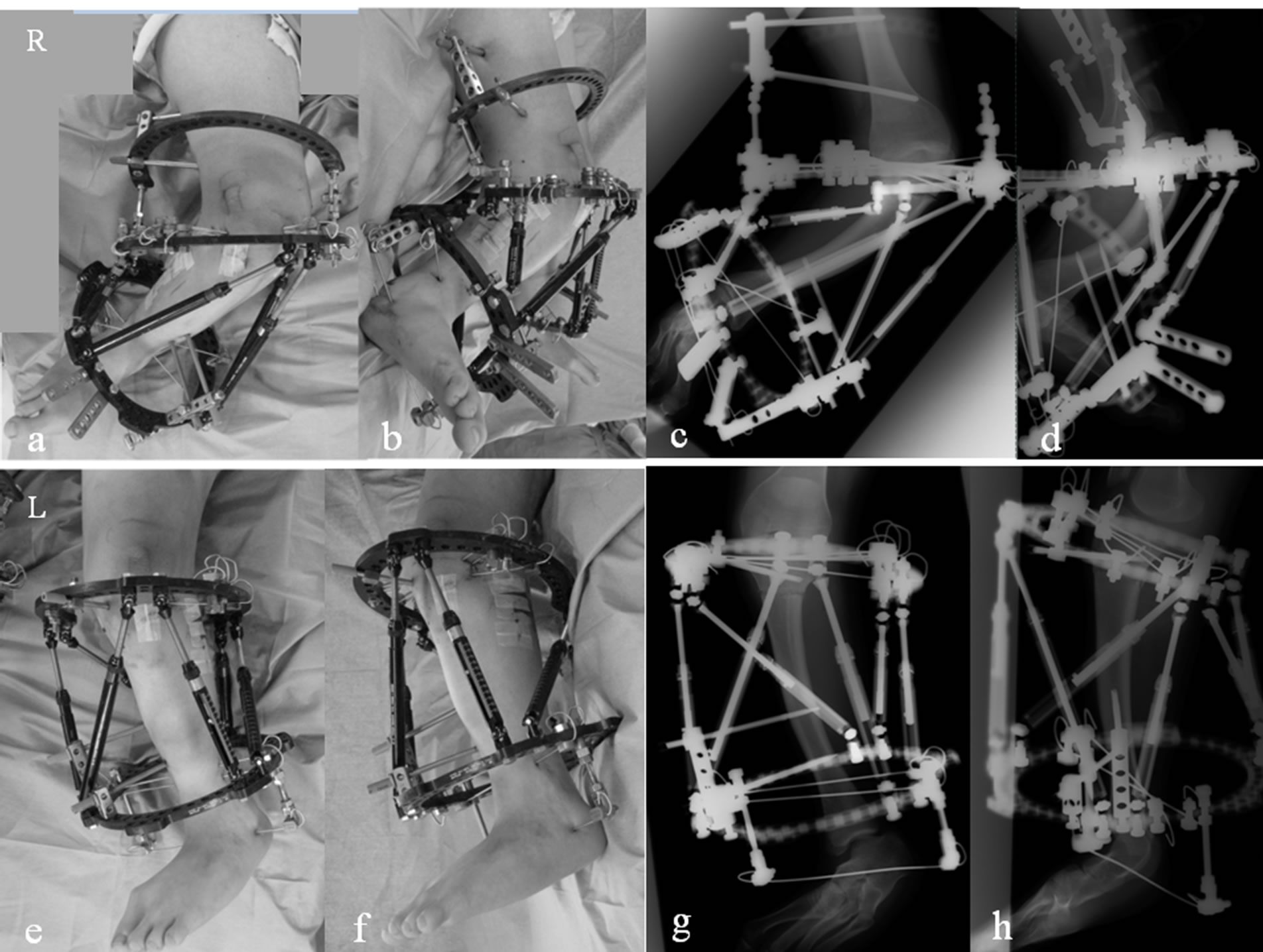
Figure 4. (a)-(d) Clinical photographs and radiographs of the right leg obtained just after the first surgery. Osteotomy was performed just distal to the tibial tubercle (proximal CORA) The TSF was put on the right tibia in combination with an Ilizarov external fixator bridging the knee joint. (e)- (h) Clinical photographs and radiographs of the left leg obtained just after the first surgery. Osteotomy was performed at the proximal CORA and the TSF was put on the left tibia.
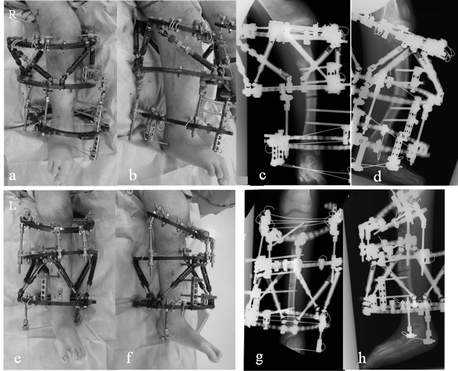
Figure 5. (a)-(d) Clinical photographs and radiographs of the right leg obtained just after the second surgery. The second osteotomies were performed at the distal CORAs with the third ring attaching to the middle of the tibiae bilaterally and bifocal corrections were performed at both CORAs using the TSF in combination with an Ilizarov external fixator system. (e)-(h) Clinical photographs and radiographs of the left leg obtained just after the second surgery.
fixators were removed.
At the latest follow-up evaluation, although anterior subluxation of the right knee was still existed, she was able to walk with a knee brace on the right side. Active range of motion of the right and left knees were 0 - 90 degree and 0 - 120 degree, respectively, with enough muscle strengths. Plain radiographs demonstrated complete bony union without angular deformity or limb length discrepancy (Figures 6(a)-(d)). This patient and her parents were informed of the purposes of the instructive case report and gave permission for us to submit our findings to a scientific journal using radiographs, images of CT scans and photographs, they were ensured that we do not include or reveal any personal information which might directly identify the patient.
3. Discussion
In patients with severe lower limb deformities complicated by angular and rotational deformities, it can be difficult for surgeons to gain a precise understanding of the nature of the problem. Preoperative assessment from radiographs is typically inaccurate because true AP and lateral radiographs are hardly obtained and physical measurements are not reliable. The resulting misunderstanding of the deformities can therefore lead to errors and failure to achieve deformity correction.
The development of 3D-CT has revolutionized the field of imaging in a variety of orthopedic surgeries. Reconstructed 3D-CT images have been widely used for preoperative planning [13-18]. Here we conducted a 3D-CT assessment of alignment for lower limb deformities using such images. A volume rendering technique [11,12] also allows generating images similar to X-ray images, which enables the magnitude of angulation to be measured from reconstructed AP and lateral images and rotation deformity to be calculated from the bird’s eye view.
However, there are several disadvantages to this method. First, radiation exposure of helical CT is still higher than that of plain radiographs, although recent helical CT scanning offers a marked reduction in the radiation dose while maintaining image quality. Second, in
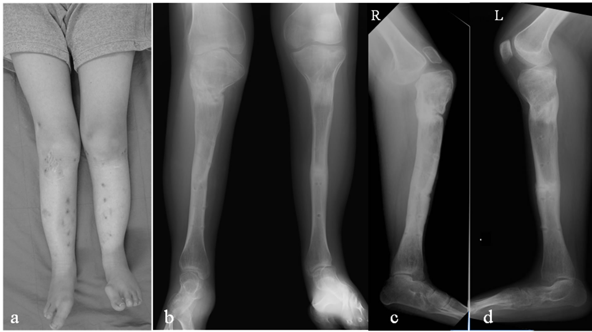
Figure 6. (a) Clinical photograph at 2 years after the first operation. (b)-(d) Radiographs after removal of the TSFs and Ilizarov fixator show complete bony union without angular deformity or limb length discrepancy.
the current filmless environment, physical measurement tools on the displayed 3D images have not been available, yet. When performing a 3D assessment using reconstructed 3D images we had to print these 3D images. We performed a malalignment test and measured the magnitude of angulation on paper because calculating the length and angle three-dimensionally is impossible on the displayed image.
Despite the higher level of radiation exposure in a 3D-CT scan, there are several advantages of 3D-CT assessment over traditional radiography: 1) ease of obtaining true AP and lateral images, 2) accurate assessment including rotational deformity, 3) no need for repeat visits to radiology, 4) no dependency on the patient’s position during scanning, and 5) the ability to view skin, muscle, tendon, and bone by changing the rendered image to highlight them.
4. Conclusion
In the present case, the reconstructed 3D-CT images made accurate assessment of the severe lower limb deformities easier, and bifocal correction without nonunion or limb length discrepancy was achieved using TSFs in combination with Ilizarov external fixator. Our experience suggests that 3D-CT assessment for severe lower limb deformities such as the current case is a valuable tool for precisely understanding deformities and performing accurate correction.
REFERENCES
- D. Paley and J. E. Herzenberg, “Principles of Deformity Correction,” Springer-Verlag, Berlin, 2002.
- D. S. Feldman, E. R. Henderson, H. B. Levine, P. L. Schrank, K. J. Koval, R. J. Patel, D. B. Spencer, D. A. Sala and K. A. Egol, “Interobserver and Intraobserver Reliability in Lower-Limb Deformity Correction Measurements,” Journal of Pediatric Orthopaedics, Vol. 27, No. 2, 2007, pp. 204-208. doi:10.1097/01.bpb.0000242441.96434.6f
- C. Achterman and A. Kalamchi, “Congenital Deficiency of the Fibula,” The Journal of Bone & Joint Surgery (British), Vol. 61B, No. 2, 1979, pp. 133-137.
- J. C. Taylor, “Correction of General Deformity with the Taylor Spatial Frame Fixator,” 2002. http://www. jcharlestaylor.com
- P. L. Docquier, D. Rodriguez and M. Mousny, “ThreeDimensional Correction of Complex Leg Deformities Using a Software Assisted External Fixator,” Acta Orthopaedica Belgica, Vol. 74, No. 6, 2008, pp. 816-822.
- M. Kucukkaya, O. Karakoyun, R. Armagan and U. Kuzgun, “Calculating the Mounting Parameters for Taylor Spatial Frame Correction Using Computed Tomography,” Journal of Orthopaedic Trauma, Vol. 25, No. 7, 2011, pp. 449-452. doi:10.1097/BOT.0b013e3181ee40c5
- L. P. Kristiansen and H. Steen, “Reduced Lengthening Index by Use of Bifocal Osteotomy in the Tibia: Comparison of Monofocal and Bifocal Procedures with the Ilizarov External Fixator,” Acta Orthopaedica Scandinavica, Vol. 73, No. 1, 2002, pp. 93-97. doi:10.1080/000164702317281486
- S. V. Vaidya, H. R. Song, S. H. Lee, S. W. Suh, S. M. Keny and S. S. Telang, “Bifocal Tibial Corrective Osteotomy with Lengthening in Achondroplasia: An Analysis of Results and Complications,” Journal of Pediatric Orthopaedics, Vol. 26, No. 6, 2006, pp. 788-793. doi:10.1097/01.bpo.0000242429.83866.97
- M. H. Griffith, M. J. Gardner, A. Blyakher and R. F. Widmann, “Traumatic Segmental Bone Loss in a Pediatric Patient Treated with Bifocal Bone Transport,” J Orthop Trauma, Vol. 21, No. 5, 2007, pp. 347-351. doi:10.1097/BOT.0b013e31805c0db5
- Sala F, Thabet AM, Castelli F, Miller AN, Capitani D, Lovisetti G, et al, “Bone transport for postinfectious segmental tibial bone defects with a combined ilizarov/taylor spatial frame technique,” Journal of Orthopaedic Trauma, Vol. 25, No. 3, 2011, pp. 162-168. doi:10.1097/BOT.0b013e3181e5e160
- P. S. Calhoun, B. S. Kuszyk, D. G. Heath, J. C. Carley and E. K. Fishman, “Three-Dimensional Volume Rendering of Spiral CT Data: Theory and Method,” Radiographics, Vol. 19, No. 3, 1999, pp. 745-764.
- J. S. Pelc and C. F. Beaulieu, “Volume Rendering of Tendon-Bone Relationships Using Unenhanced CT,” American Journal of Roentgenology, Vol. 176, No. 4, 2001, pp. 973-977. doi:10.2214/ajr.176.4.1760973
- R. Bilić, V. Zdravković and Z. Boljević, “Osteotomy for Deformity of the Radius. Computer-Assisted Three-Dimensional Modelling,” The Journal of Bone & Joint Surgery (British), Vol. 76B, No. 1, 1994, pp. 150-154.
- T. Shimizu, F. Fujioka, H. Gomyo, K. Isobe and K. Takaoka, “Three-Dimensional Starch Model for Simulation of Corrective Osteotomy for a Complex Bone Deformity: A Case Report,” Foot & Ankle International, Vol. 24, No. 4, 2003, pp. 364-367.
- H. S. Hosalkar, S. Jones, J. Hartley and R. Hill, “ThreeDimensional Tomography of Relapsed Infantile Blount’s Disease,” Clinical Orthopaedics and Related Research, Vol. 431, 2005, pp. 176-180. doi:10.1097/01.blo.0000150463.79616.48
- M. Kamegaya, T. Saisu, N. Ochiai and H. Moriya, “Preoperative Assessment for Intertrochanteric Femoral Osteotomies in Severe Chronic Slipped Capital Femoral Epiphysis Using Computed Tomography,” Journal of Pediatric Orthopaedics B, Vol. 14, No. 2, 2005, pp. 71-78. doi:10.1097/01202412-200503000-00003
- L. N. Metz and S. Burch, “Computer-Assisted Surgical Planning and Image-Guided Surgical Navigation in Refractory Adult Scoliosis Surgery: Case Report and Review of the Literature,” Spine, Vol. 20, No. 33, 2008, pp. E287-292. doi:10.1097/BRS.0b013e31816d256e
- A. L. Simpson, B. Ma, B. Slagel, D. P. Borschneck and R. E. Ellis, “Computer-Assisted Distraction Osteogenesis by Ilizarov’s Method,” International Journal of Medical Robotics, Vol. 4, 2008, pp. 310-320. doi:10.1002/rcs.211