Journal of Power and Energy Engineering
Vol.04 No.12(2016), Article ID:72621,19 pages
10.4236/jpee.2016.412001
Harmonic Propagation from the Low Voltage Four-Wire Delta Systems
Jandecy Cabral Leite1, Manoel Socorro Santos Azevedo1, Ubiratan Holanda Bezerra2, Ignacio Pérez Abril3, Carlos Alberto de León Benítez3
1Department of Electrical and Industrial Engineering, Institute of Technology and Education Galileo of Amazonia (ITEGAM), Manaus, Brazil
2Department of Electrical Engineering, Federal University of Para, Belém, Brazil
3Department of Electrical Engineering, Central University of Las Villas (UCLV), Santa Clara, Cuba

Copyright © 2016 by authors and Scientific Research Publishing Inc.
This work is licensed under the Creative Commons Attribution International License (CC BY 4.0).
http://creativecommons.org/licenses/by/4.0/


Received: September 27, 2016; Accepted: December 5, 2016; Published: December 8, 2016
ABSTRACT
The electric networks for the distribution to low voltage costumers can be configured in different layouts. Two main approaches are used: the European system composed by three-phase distribution transformers or the North American system composed by single-phase distribution transformers and three-phase transformer banks of single-phase transformers. With respect to harmonic analysis, much more attention has been focused on the three-phase balanced systems arrangements than on the unbalanced four-wire delta system extensively used to supply low voltage loads of 120/240 V. Different authors have shown the three-phase power systems modeling on a phase- coordinates frame. However, the presence of significant asymmetries in the network forces the need of adding a new phase-coordinates model to represent the three-phase transformers banks of two or three single-phase transformers in its various connections. Several papers treat the use of harmonic analysis programs based on a phase- coordinates frame to study the Wye or Delta connected three-phase systems. However, the commonly used four-wire delta connected systems are not fully treated in literature. This paper presents a phase-coordinates model for the representation of the commonly used three-phase transformer banks of three or two single-phase transformers, and single-phase distribution transformers for the harmonic analysis of the four-wire delta connected systems. The harmonic analysis method based on the presented model is used to examine the characteristics of this kind of distribution system with respect to the penetration of harmonics currents from loads to the primary system.
Keywords:
Harmonic Analysis, Phase-Coordinates, Four-Wire Delta Systems

1. Introduction
The electric networks for the distribution to low voltage costumers can be configured in different layouts. Two main approaches are used: the European system composed by three-phase distribution transformers or the North American system composed by single-phase distribution transformers and three-phase transformer banks of single-phase transformers. With respect to harmonic analysis, much more attention has been focused on the three-phase balanced systems arrangements than on the unbalanced four- wire delta system extensively used to supply low voltage loads of 120/240 V. The phase- coordinates models can be used for the analysis of distribution systems at fundamental frequency as well as for other frequencies and are well suited for the harmonic analysis of unbalanced networks.
The formulation of the harmonic power flow method in a phase-coordinates frame, besides allowing for a more accurate modeling of unbalanced networks, allows the specification of harmonic injections of any type: single-phase or three-phase of the desired sequence. Therefore, it is possible to study the effect of the non-linear loads according to its features and connection to the circuit.
Different authors have shown the three-phase power systems modeling on a phase- coordinates frame [1] - [9] . However, the presence of significant asymmetries in the network forces the need of adding a new phase-coordinates model to represent the three- phase transformers banks of two or three single-phase transformers in its various connections [6] [7] [8] [9] .
Several papers treat the use of harmonic analysis programs based on a phase-coor- dinates frame to study the Wye or Delta connected three-phase systems [3] [10] [11] [12] . However, the commonly used four-wire delta connected systems are not fully treated in literature. This paper presents a phase-coordinates model for the representation of the commonly used three-phase transformer banks of three or two single-phase transformers, and single-phase distribution transformers for the harmonic analysis of the four-wire delta connected systems. The harmonic analysis method based on the presented model is used to examine the characteristics of this kind of distribution system with respect to the penetration of harmonics currents from loads to the primary system.
2. Harmonic Penetration Analysis
One of the most widely used techniques for solving the harmonic power flow problem is the so called harmonic penetration study [13] [14] [15] [16] , which represent the non- linear load current injections by constant current sources of every one of the studied frequencies.
The magnitude and phase angle of each of these current sources are calculated by the results of a previously solved fundamental frequency power flow and considering the typical harmonic spectrum of the non-linear loads presented in the system [13] .
The procedure lies in the concept that the wave forms of the non-linear loads distorted currents are independent of the voltage magnitude and wave form. In that way, a fixed relation between each harmonic current component and the fundamental frequency current is considered.
Thus, the magnitude and phase angle of the hth harmonic are related with the fundamental frequency current and the typical harmonic spectrum of the load by:
 (1)
(1)
 (2)
(2)
Once all the harmonic current injections are calculated, the resulting harmonics voltages on the system buses are determined by means of:
 (3)
(3)
where V(h), Z(h) and I(h), are the voltages vector, the bus impedance matrix and the injected currents vector for each hth harmonic frequency.
The method decouples the voltages calculation for each frequency, so the process can be cyclically repeated for every harmonic frequency presented on any of the non-linear loads.
Concluded the harmonic penetration study, a complete set of harmonic voltages on every bus is obtained and with it, all the harmonic branch currents can be calculated.
The network bus impedance matrix for each frequency is determined as the inverse of the bus admittance matrix Y(h) that is built from established models for the different elements of the electrical system [3] .
Using the positive, negative and zero sequence models of the system’s elements the bus impedance matrices of different sequences can be found.
However, some types of electrical distribution networks of industrial, commercial or service facilities are so unbalanced that a more effective modeling can be achieved by using phase-coordinates models.
2.1. The Phase-Coordinates Frame
In essence, the phase-coordinates modeling is able to determine the voltage at all the nodes with respect to a reference node, which is usually the ground, but in the case of a not grounded system, or an asymmetric network as the four-wire delta connected system is a fictitious reference node.
Again, the resulting harmonics voltages of the system nodes are determined by means of (3). Thus, the key elements in the analysis are the determination of the vector I(h) and the matrix Z(h) in the phase-coordinates frame.
The harmonic power penetration analysis in phase-coordinates allows the specification of current injections of any type: single-phase or three-phase of the desired sequence. Therefore, it is possible to study the effect of non-linear loads according to their characteristics and their connection to the circuit.
In order to represent a non-linear load current injection of N phases, a typical harmonic spectrum of equal number of phases must be used.
The fundamental apparent power S(1) of the load is the sum of the power of each phase n:
 (4)
(4)
On the other hand, as the magnitude and phase angle relations between the fundamental currents of the N phases of the typical harmonic spectrum must be fulfilled, it can be expressed a linear relation between each phase fundamental current and their correspondent phase fundamental current in the considered harmonic spectrum.
 (5)
(5)
To determine the complex parameter μ, the relation (5) is substituted in (4) obtaining:
 (6)
(6)
From where:
 (7)
(7)
Calculated μ, the fundamental and other harmonic currents of each phase can be obtained by:
 (8)
(8)
 (9)
(9)
where fμ represents the phase angle of μ.
Normally, typical harmonic spectrums are employed to represent the non-linear loads currents injections, however, a non-typical harmonic spectrum can be employed to represent a non-typical operation condition of the harmonic producing loads: partial load, voltages unbalance, non-characteristic harmonics generation, etc.
To determine the bus impedance matrix for every frequency, there network nodal admittance matrix for each frequency must be formed, which comprises the adding of the nodal admittance sub-matrices of different elements such as the transformers, feeders, machines and other passive elements such as capacitor banks, harmonic filters, etc.
The model of three-phase transformers and three-phase transformer banks is one of the most complicated parts of the network model, due to the diversity of their connections and configurations. However, the effective network overlapping technique presented by Chen [6] [7] [8] simplifies the formation of the possible three-phase transformers and three-phase transformer banks configurations.
In [17] was presented a new model for the single-phase distribution transformer with center-tap in the secondary winding that considers the relation m between the impedances of the primary and secondary winding of the transformer. This ratio depends on:
 (10)
(10)
where ZFULL represents the full-winding impedance and ZHALF the half-winding impedance of the distribution transformer.
Taken into account that the series reactance of the transformer varies with the harmonic order h, and considering the commonly employed values for the half-winding impedance of the transformer [18] , the relation m can be calculated depending on the secondary winding construction by:
 (11)
(11)
where R and X are the full-winding resistance and reactance of the transformer at the fundamental frequency.
Using that model, this paper presents the admittance matrices of the commonly used three-phase transformer banks configurations. Besides, for each type of transformer bank, an analysis of the harmonics penetration in the primary circuit is achieved to highlight the characteristics of this system.
2.2. The Floating Wye-Delta Transformer Bank
The floating Wye-Delta transformer bank (Figure 1) is composed by a lighting leg transformer (1) and two equal power?leg transformers (2) and (3) of minor capacity.
The admittance matrix of this transformer bank considering a relation m between the primary and the secondary winding impedances of the lighting?leg transformer (1) is:
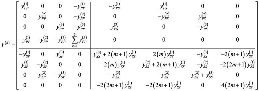 (12)
(12)
where yPP, yPS and ySS of each transformer are calculated as follows:

Figure 1. Floating Wye-Delta transformer bank.
 (13)
(13)
 (14)
(14)
 (15)
(15)
And y0 is the admittance shunt that represents the non-load losses and y is the series full-winding admittance of the transformer (both calculated for the frequency h), while α and β are the corresponding tap selection for primary and secondary respectively.
2.3. The Open Wye-Open Delta Transformer Bank
The open Wye-open Delta transformer bank (Figure 2) is composed by a larger lighting-leg transformer and a single power-leg transformer. The primary neutral must be grounded, so this node is eliminated from the analysis.
The admittance matrix of this transformer bank considering a relation m between the primary and the secondary winding impedances of the lighting?leg transformer (1) is:
 (16)
(16)
2.4. The Single-Phase Distribution Transformer
The single-phase distribution transformer (Figure 3) does not supply three-phase loads.
The admittance matrix of this transformer, provided that the primary neutral is grounded, is:

Figure 2. Open Wye-open Delta transformer bank.

Figure 3. Single-phase distribution transformer.
 (17)
(17)
3. System Analysis
The presented phase-coordinates model has been implemented in a Matlab 2010 application to evaluate the harmonics penetration from the low voltage four-wire delta connected non-linear loads into the primary medium voltage feeder of a grounded Wye connected distribution system.
The test system of Figure 4 is a three-phase four-wire 4160 V primary distribution feeder of four conductors (three-phases and multi-grounded neutral) 3/0 AWG that is supplied at bus N1 by a three-phase power source of 150 MVA of short circuit and x/r ratio equals 10.
At the buses N1, N2 and N3 (250 meters apart each other) three equal transformer banks supply the loads at the low voltage buses n1, n2 and n3 that consists in a mixture of 240 V three-phase and 120 V single-phase loads.
Two types of single-phase distribution transformers are employed to form the transformer banks (Table 1) of the example.
In order to evaluate the harmonic injections effect of the non-linear loads, only this kind of loads will be considered in the example cases. The data of the loads supplied at the low voltage buses are (Table 2).
These non-linear loads have been represented by the typical harmonic spectrum (Table 3) of a three-phase six pulse converter (1) and a branch circuit serving computer loads (2).
Three cases are analyzed:
1) Three floating Wye-Delta transformers banks.
2) Three open Wye-open Delta transformers banks.
3) Three single-phase distribution transformers.
All the currents and voltages that will be shown are in per unit values of 100 kVA bases.

Figure 4. Test system.

Table 1. Distribution transformers data.
Table 2. Non-linear loads data.
Table 3. Non-linear loads harmonic spectrums.
3.1. Case 1
In this case, three floating Wye-Delta transformers banks are used with the following connections (Table 4).
Table 4. Case 1 banks connections.
*AB, BC or CA is the mid-tap phase in the lighting-leg transformer.
Single phase non-linear loads are supplied by the lighting leg transformers. If the both secondary sections of each lighting-leg transformer supply half of the single-phase load, no current flows through the mid tap.
Due the floating primary neutral, the summation of primary currents must be zero. So, it can be shown, that the primary currents in the nodes 1, 2 and 3 (Figure 1) depend on:
 (18)
(18)
where k is the transformer relation and IL1 is the current of the single-phase load that is connected to the lighting-leg transformer secondary.
Considering the expression (18), all the single-phase load harmonic currents will flow through the transformer bank and so harmonics of all sequences will appear in the primary currents. The obtained results for the first transformer bank (Figure 5) supplying only the single phase non-linear load confirms this conclusion.
On the other hand, the flow through the feeder of the harmonics produced for all the single-phase loads is presented (Figure 6).
As it can be seen (Figure 6), triples harmonics can flow through the A, B, C phases, but not through the multi-grounded neutral (Gnd) because of the floating primary neutral of the transformer banks. In a perfectly balanced case like the presented, the triples harmonics will be eliminated and the non-triples harmonics will be balanced after the addition of the primary currents of the three transformer banks. However, this perfect situation is very rare in practice.

Figure 5. Harmonic currents in the transformer bank due to the single-phase load (case 1).

Figure 6. Harmonic currents in the feeder due to the single-phase loads (case 1).
With regard to the harmonics of the secondary voltages, those are influenced by the connection of the single-phase non-linear load and the type of lighting-leg transformer employed.
If the single-phase non-linear load is equally divided between the both secondary sections of the lighting-leg transformer, the harmonics of the line to line voltages at the secondary are equal in the both secondary sections of this transformer (Figure 7).
However, if all the single-phase non-linear load is connected between the phases A and AB (mid tap between A and B), the line to line voltages at the secondary depend on the windings construction of the lighting-leg transformer. The obtained results are shown in Figure 8 and Figure 9 for interlaced and non-interlaced windings transformer respectively.
As it can be seen (Figure 9), the increased reactance of the non-interlaced windings transformer increase the presence of harmonics in the line to line voltage at the position in which the single-phase load is connected.
The penetration of the balanced three-phase non-linear load harmonics in the primary feeder (Figure 10) follows the known rules for balanced three-phase systems. Only the unbalanced triples harmonics can flow through the feeder.
With respect to the harmonics in the secondary line to line voltages, it can be seen (Figure 11) that these voltages are lower in the secondary of the lighting-leg transformer. This is caused by the reduced impedance of this larger size transformer.
3.2. Case 2
In this case, three open Wye-open Delta transformers banks are used with the following connections (Table 5).

Figure 7. Harmonics of the secondary line to line voltages (equally loaded sections).

Figure 8. Harmonics of the secondary line to line voltages (unequally loaded sections in an interlaced windings transformer).

Figure 9. Harmonics of the secondary line to line voltages (unequally loaded sections in a non- interlaced windings transformer).

Figure 10. Harmonic currents in the feeder due to the three-phase loads (case 1).

Figure 11. Line to line voltages at the secondary due to the three-phase load (case 1).
Table 5. Case 2 banks connections.
*AB, BC or CA is the mid-tap phase in the lighting-leg transformer.
In this transformer bank, the single-phase load currents only flow through the lighting- leg transformer, so the entire effect of this harmonics is produced on the primary phase in which the lighting-leg transformer is connected (Figure 12).
As the single-phase load harmonics flow freely through the lighting-leg transformers, the triples harmonics penetrate the primary feeder and are added to the current in the multi-grounded neutral conductor (Figure 13).
In a perfectly balanced case like the presented, the triples and non-triples harmonics will be balanced in the feeder’s phases after the addition of the primary currents of the three transformer banks. On the other hand, the triples harmonics contents of the neutral current are always increasing.
With respect to the three-phase load effect, it is supplied by the two transformers, so the harmonics of all frequencies penetrate two phases and the neutral of the primary feeder (Figure 14).
In the presented case, the positive and negative sequence harmonics will be balanced in the feeder’s phases after the addition of the primary currents of the three transformer banks (Figure 15).
3.3. Case 3
In this case, three single-phase distribution transformers are used with the following connections (Table 6).
In this case, the load current only flow through the lighting-leg transformer, so the entire effect of this harmonics is produced on the primary phase in which the lighting- leg transformer is connected (Figure 16).
As the single-phase load harmonics flow freely through the lighting-leg transformers, the triples harmonics penetrate the primary feeder and are added to the current in the multi-grounded neutral conductor (Figure 17).
4. Conclusions
With respect to harmonic analysis, the four-wire delta connected system has the handicap that the single-phase 120 V load is connected only to the lighting-leg transformer.

Figure 12. Harmonic currents in the transformer bank due to the single-phase load (case 2).

Figure 13. Harmonic currents in the feeder due to the single-phase loads (case 2).

Figure 14. Harmonic currents in the transformer bank due to the three-phase load (case 2).

Figure 15. Harmonic currents in the feeder due to the three-phase loads (case 2).

Figure 16. Harmonic currents in the transformer due to the single-phase load (case 3).

Figure 17. Harmonic currents in the feeder due to the single-phase loads (case 3).
Table 6. Case 3 transformers connections.
*AB, BC or CA is the mid-tap phase in the lighting-leg transformer.
So, this system is very unbalanced by its structure and the harmonics cancellation is rarely obtained. That is why harmonics of all the frequencies can be found in the feeder phases.
The use of both the open Wye-Delta transformer banks and the single-phase distribution transformers permits the zero sequence harmonics circulation through the multi-grounded neutral conductor of the primary feeder.
The phase-coordinates model developed for the harmonic analysis is able to represent with good accuracy unbalanced networks like the presented. Their results permit the evaluation of the influence on the secondary line to line voltages of the unequal load in both sections of the secondary of the lighting-leg transformer considering its windings construction.
Acknowledgements
The authors acknowledge the Institute of Technology Galileo of Amazon (ITEGAM) and the Amazonas Research Foundation (FAPEAM) for the financial support as doctorate grant for performing this work.
Cite this paper
Leite, J.C., Azevedo, M.S.S., Bezerra, U.H., Abril, I.P. and de León Benítez, C.A. (2016) Harmonic Propagation from the Low Voltage Four-Wire Delta Systems. Journal of Power and Energy Engineering, 4, 1-19. http://dx.doi.org/10.4236/jpee.2016.412001
References
- 1. Arrillaga, J. and Arnold, C.P. (1990) Computer Analysis of Power Systems. Wiley, New York.
https://doi.org/10.1002/9781118878309 - 2. Arrillaga, J. and Watson, N.R. (2001) Computer Modeling of Electrical Power Systems. 2nd Edition, Wiley, New York.
https://doi.org/10.1002/9781118878286 - 3. Arrillaga, J. and Watson, N.R. (2003) Power Systems Harmonic. 2nd Edition, Wiley, New York.
https://doi.org/10.1002/0470871229 - 4. Irving, M.R. and Al-Othman, K. (2003) Admittance Matrix Models of Three-Phase Transformers with Various Neutral Grounding Configurations. IEEE Transactions on Power Systems, 18, 1210-1212.
https://doi.org/10.1109/TPWRS.2003.814905 - 5. Moorthy, S. and Hoadley, D. (2002) A New Phase-Coordinate Transformer Model for Ybus Analysis. IEEE Transactions on Power Systems, 17, 951-956.
https://doi.org/10.1109/TPWRS.2002.804996 - 6. Chen, T.H. and Yang, W.C. (1998) Modeling and Analysis of Three-Phase Four-Wire Distribution Transformers with Mid-Tap on the Secondary Side. International Conference on Energy Management and Power Delivery, Vol. 2, 723-727.
- 7. Chen, T.H., Yang, W.C., Guo, T.Y. and Pu, G.C. (2000) Modeling and Analysis of Asymmetrical Three-Phase Distribution Transformer Banks with Mid-Tap Connected to the Secondary Neutral Conductor. EPRI, 54, 83-89.
- 8. Chen, T.H. and Yang, W.C. (2001) Analysis of Multi-Grounded Four-Wire Distribution Systems Considering the Neutral Grounding. IEEE Transactions on Power Delivery, 16, 710-717.
https://doi.org/10.1109/61.956760 - 9. Kang, J. and Fu, L.J. (2008) Three-Phase Transformer Models for Load Flow Calculations in Power Systems. International Conference on Electrical Machines and Systems (ICEMS 2008), China, October 2008, 4114-4118.
- 10. Sainz, L., Caro, M. and Pedra, J. (2004) Study of Electric System Harmonic Response. IEEE Transactions on Power Delivery, 19, 868-874.
https://doi.org/10.1109/TPWRD.2004.825299 - 11. Sainz, L., Pedra, J. and Caro, M. (2005) Steinmetz Circuit Influence on the Electric System Harmonic Response. IEEE Transactions on Power Delivery, 20, 1143-1150.
https://doi.org/10.1109/TPWRD.2004.834339 - 12. Sainz, L., Pedra, J. and Herraiz, S. (2005) Capacitor and Shunt Filter Unbalance Influence on the Electric System Harmonic Response. IEEE Transactions on Power Delivery, 20, 1522-1531.
https://doi.org/10.1109/TPWRD.2004.838630 - 13. Task Force on Harmonics Modeling and Simulation (1996) Modeling and Simulation of the Propagation of Harmonics in Electric Power Networks Part I: Concepts, Models, and Simulation Techniques. IEEE Transactions on Power Delivery, 11, 452-465.
- 14. Task Force on Harmonics Modeling and Simulation (1996) Modeling and Simulation of the Propagation of Harmonics in Electric Power Networks Part II: Sample Systems and Examples”. IEEE Transactions on Power Delivery, 11, 466-474.
https://doi.org/10.1109/61.484131 - 15. Oliveira, L.C.O., et al. (2011) Harmonic Propagation Analysis in Electric Energy Distribution Systems. 11th International Conference on Electrical Power Quality and Utilisation (EPQU), Lisbon, 2011, 1-6.
- 16. Guide for Applying Harmonic Limits on Power Systems (Draft 7). P519A Task Force of the Harmonics Working Group. IEEE 2000.
- 17. Leite, J.C., Abril, I.P., Tostes, M.E.L. and Oliveira, R.C.L. (2012) Frequency Scan on Phase-Coordinates Frame for Unbalanced Systems. Electric Power Systems Research, 93, 113-119.
https://doi.org/10.1016/j.epsr.2012.07.013 - 18. Short, T.A. (2004) Electric Power Distribution Handbook. CRC Press, Boca Raton.