Journal of Computer and Communications
Vol. 1 No. 2 (2013) , Article ID: 32286 , 10 pages DOI:10.4236/jcc.2013.12002
The Overload Reduction in SIP Servers through Exact Regulation of the Retransmission Timer of the Invite Message
![]()
Department of Computer Engineering, Ferdowsi University of Mashhad, Mashhad, Iran.
Email: Ahmadreza.Montazerolghaem@stu.um.ac.ir, yaghmaee@ieee.org
Copyright © 2013 Ahmadreza Montazerolghaem, Mohammad Hossein Yaghmaee. This is an open access article distributed under the Creative Commons Attribution License, which permits unrestricted use, distribution, and reproduction in any medium, provided the original work is properly cited.
Received May 4th, 2013; revised May 24th, 2013; accepted May 30th, 2013
Keywords: Reduction of Session Initiation Time; SIP (Session Initiation Protocol); Invite Message Retransmission Timer; Overload Reduction
ABSTRACT
To initiate voice, image, instant messaging and general multimedia communication, the Session communication must initiate between two participants. SIP (Session initiation protocol) is an application layer control, which task is creating management, and terminating this kind of Sessions. With regard to the independence of SIP from the Transport layer protocols, the SIP messages can be transferred on a variety of Transport layer protocols such as TCP or UDP. The mechanism of Retransmission, which has been embedded in SIP, is able to compensate the missing Packet loss, if needed. The application of this mechanism is when SIP messages are transmitted on an unreliable transmission layer protocol such as UDP. This mechanism, while facing with SIP proxy with overload, causes excessive filling of proxy queue, delays the increase of other contacts and adds the amount of the proxy overload. We in this article, while using UDP, as the Transport layer protocol, by regulating the Invite Retransmission Timer appropriately (T1), have improved the SIP functionality. Therefore, by proposing an Adaptive Timer of Invite message retransmission, we have tried to improve the time of Session initiation and as a result, improving the performance. The performance of the proposed SIP, by the SIPP software in a real network environment has been implemented and evaluated and its accuracy and performance has been demonstrated.
1. Introduction
In recent years, the presence of Internet-based networks can be seen everywhere. This is itself has become a factor to popularize the dial-up calls via IP network. We can name some cases among the factors that has caused more welcoming of such communications. The first case is the economic problems, the internet phone call, especially for international call is much cheaper than the typical phone calls. The next case is the development of the IP communication in a variety of applied equipments. The personal computers connect to the internet easily and through different modes. Even the presence of IP in cell phones is also one of the factors that have caused the further development of Internet in comparison to the other technologies. Another factor is the further use of Packet Switched architecture instead of Circuit Switched, which can itself make optimum use of the resources.
In simultaneous communications and two-way communications such as audio and video communications, file transfer, exchanging instant message and general multimedia sessions expressed, which the communication is on line, first a session must initiate among the participants. Its most important aspects of these types of communications and especially the internet phone call contact, is signaling. This signaling is responsible for the task of initiating and managing of the session. One of the very suitable protocols in this field is SIP, which its task is: creating, modifying and terminating the session. One of the key components of the delay-sensitive applicable programs such as voice and image transmission by Internet is the time required to start-up the session, which is highly effective in Protocol efficiency. The reduction of this period of time causes the increase of the SIP server transmitting and consequently, it improves its efficiency, on the other hand, it will cause more acceptability of user [1]. Due to the importance of this issue, some researches have been done, to reduce the necessary time to create the session in progress, which some examples are mentioned below.
We in this article to improve the session initiation time in UDP protocol, through appropriate regulation of the Timer, sending of the Invite message retransmission, we improve the session initiation time as well as reducing the missed calls.
2. Related Work
As we can use certain servers specified for SIP, for a session, increasing the number of the servers, the load distribution among them or raising the servers processing capability can help reduce the time to initiate the session [1]. We should know that these changes are costly and in some cases difficult. Another way is using the Stateless mode instead of Stateful in the servers [1-3]. But this method has a major problem, so that a complete history of communication will not be available [2]. Another method used to reduce the time used for session initiation, is to remove users’ authentication confirmation, which has the highest positive impact on reducing the time of the session initiation, but due to the nature of the Internet network and in some cases, the necessity of using authentication confirmation, using this method has also considerable problems. On the other hand, another important component, which must be considered, is the percentage of sessions missed, which its reduction influence on the Protocol is evident. Generally, with regard to the compatibility in the interoperability, UDP is considered as the standard transmission protocol for SIP, but we should know that the other protocols such as TCP and SCTP are also reliable and applicable [3] (in some cases, the use of connection-oriented protocols are essential, for example, in the circumstances, which the SIP message transmission length is more than MTU [4]). Whereas, according to the standard, all the implementations of SIP must back-up TCP and UDP [5]. Now considering this issue, through appropriate selection of Transmission protocol and also by selecting UDP as Transmission layer protocol, by regulating SIP Timers, we can provide conditions to increase the protocol effectiveness, in various network conditions and through considering the amount of Packet loss and Delay and the amount of Traffic load of SIP. As the session initiator can determine the Transmission protocol and the responder complies with him and making decision for this selection is done in each Nod of the SIP network [6], therefore, we can take measures in each point of the network considering the network conditions for selection [7-9]. In this case, the selection is done dynamically and without spending certain expense we can increase the transmission and as a result, the high efficiency [10,11].
The rest of this paper is organized as follows: Section 3 includes an overview to improve SIP efficiency while using UDP. Section 4 includes Timer T1 Adaptive. Section 5 includes estimating the Timer T1 Adaptive.
3. To Improve SIP Efficiency While Using UDP
As it has already been stated, in some cases using a connection-oriented protocol such as TCP is essential as the Transmission layer protocol in SIP. Here we consider the situation that due to any reason, UDP has been considered as Transmission layer protocol for SIP. In this situation the regulations will be in a way that the efficiency of SIP improves. Here we also consider two important parameters are as the assessing criteria of SIP efficiency. The first parameter is the required time for session initiation and the next parameter is the ratio of the sessions’ loss to the sessions’ start-up. Now we have tried to take actions to increase the Protocol efficiency by accurate regulating the T1 retransmission Timer on SIP, compared to the increase of the efficiency of the Protocol Action. As we know, UDP protocol is an unreliable protocol and a mechanism to guarantee the delivery of the messages to the destination does not exist. On one side, sometimes due to some of its advantages, it is selected as the Transmission layer protocol, which in such cases if the guaranteed delivery of packets to the destination is important, the management mechanism must be implemented in the applicable layer. Regarding SIP such conditions are also applied. For this purpose, some Timers have also been placed that for the time being, we will consider Timer T1, which is the most important ones.
3.1. Application of Timer T1
In SIP, some Timers have been placed to manage the messages’ retransmission in the message loss cases, among which Timer T1 can be named as the most important one. This Timer specifies the initial amount Timer A as well as the amount of B Timer, and the default amount of SIP, is 500 milliseconds. Timer A is the Invite message retransmission Timer, which the following equation is between Timer A and Timer T1:
 (1)
(1)
In this formula J is the times of Invite message retransmission. As we can see in the above equation, message retransmission is in the form of a symbol of the initial amount of the Timer T1. This means, when the Invite message is sent, UAC for a period of A = T1 waits to receive a temporary reply (for example: 180 ringing) or final reply (200 OK) from UAS and if it doesn’t receive any reply up to the end of Timer A, through using the formula mentioned, it will reset Timer A again and transmits Invite message again. As it is observed, at every stage of Invite retransmission, the amount of Timer A will be double, in order to increase the probability of receiving the reply. This action will continue as much (for 7 times), so that Timer B will be terminated, this Timer is equivalent to 64 times of Timer T1 according to the following formula:
 (2)
(2)
As in the formula above can be observed, the amount timer B, is 64 times initial Timer T1, which means, after the elapse of this period of time and not receiving a final reply, Time-out will occur in UAC and the contact will totally drop out. Now, according to the above article on Timer T1 has very important impact on the messages retransmission as well as contact drop-outs and its accurate regulating can help a lot to improve the efficiency, we consider regulating this Timer in the direction of improving the average time of the sessions initiation as well as reducing the sessions loss.
3.2. Test-Implementation Plan of Protocol, by SIPp Software—The Adjustments Done in SIPp Software
SIPp is a testing tool to study the performance and also functionality of SIP hardware and software implementation, which has been created by HP (Hewlett Packard). This software is practicable on LINUX, therefore, if we want to be able to implement and run it on Windows; we have used the Cygwin software, which provides necessary ports for implementation on Windows. In this software various types of SIP scenarios can be created in XML language and import them. In this section, we install SIPp and Cygwin, on two separate computers. Then, we set a network connection between the two computers. One computer has been considered as UAS and another as UAC.
As we have already mentioned, we must write and apply the desired SIP scenario with XML language and present it to SIPp. Therefore, in one computer UAS scenario and in the other one the UAC is written and applied. These two scenarios were written in a way that through sending the Invite message, it starts up the session and through sending bye message it terminates the session.
It should be noted that it has been tried to use the network natural delay as Delay through conducting the test on different networks and to perform the complete tests, simulated Delay in SIPp software has been used. About implementation of Packet loss, also the exertion of Packet loss has been used in software in SIPp software. To perform the tests a number of 1000 calls with a rate of 100 calls per second have been set up. The broad band of the test environment has also been 4 megabytes per seconds and to be able to assess SIP behavior accurately, only signaling traffic has been exchanged.
Regulating Timer T1
As it has already been noted, Timer T1 specifies the initial values of A and B Timers, which respectively have the task of regulating the retransmission of Invite message and the sessions being Time-out. Therefore, according to the above tasks, which specify the function of Timer T1, the following points regarding the Timer T1 regulation are noteworthy:
If in the network the delay is low, the Timer T1 amount can be reduced to prevent waiting in vain, in case of deterioration of the transmitted Invite message from UAC or temporary transmitted reply from UAS.
If the network delay is higher than Timer T1 default (which is 500 milliseconds) (such as satellite transmission environment or due to sectional density), the Timer amount must be added to prevent retransmission and vain Invite messages, which replies are on the track, due to the network natural delay.
If the delay in receiving the reply from UAS is due to CPU high load in the mentioned Nod, through increasing the time of Timer T1, we can reduce the working load of UAS.
In case of the existence of Loss in the environment and the Invite message being lost or the temporary reply, it is better to reduce the speed of Invite message retransmission through increasing the time of Timer T1, so that through this way, congestion can be reduced.
If Invite messages or temporary reply reaches the destination defectively, it is better to take action to retransmit the message Invite immediately by reducing the Time T1, to prevent waiting for a reply that will never be received.
3.3. Study of the Delay Effect
Here the delay effect has been evaluated when the amount of the network Loss has been considered zero. Therefore, the results obtained in this part, evaluating the Delay effect disregarding the Loss. This part of the experiment has been performed in several steps. Here we want to evaluate the Delay effect considering the various values of Timer T1, while UDP has been set up as a Transmission layer protocol. The method of assessment is in such a way that by average measuring the time required to initiate a session, the percentage of the missed calls, as well as the percentage of the Invite messages, which have been retransmitted, we have studied the performance of the protocol. It is necessary to mention that the amount of the retransmission of the Invite messages as a criterion to study the usage of the band width and also the load process in UAS will be reviewed. Figure 1 represents SST changes (Session Start-up Time) to Delay changes according to T1 amounts.
As it can be observed in Figure 1 by reducing the amount of Timer T1, we can reduce the average time of the Session initiation and increase the efficiency of the Protocol but here a Tradeoff exists. The important issue is transmitting Invite messages that in situations where the amount of Delay is much more than the amount the Timer T1, retransmission is very high and it will cause a waste of bandwidth as well as the use of the processor in UAS. In Figure 2, it is obvious that by reducing the Timer, the amount of Invite message retransmission will be highly increased. In this figure we can see that the charts have exponential shape, which the reason is the exponential nature of Timer A compared to the Timer T1 and at intervals of 2 times compared to the previous retransmission, at each stage, the Invite message is retransmitted.
Another parameter, that should be considered here, is the rate of call drop. Figure 3 shows that in situations where Timer T1 is much smaller than the amount of De lay, it will cause loss of calls.
3.4. The Study of Loss Effect
The Loss effect in conditions has been evaluated that the
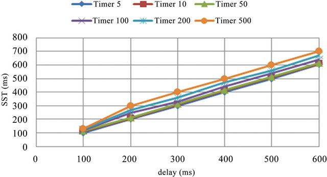
Figure 1. Chart of comparing the average changes of Session initiation time to Delay changes for different values of T1 in milliseconds.
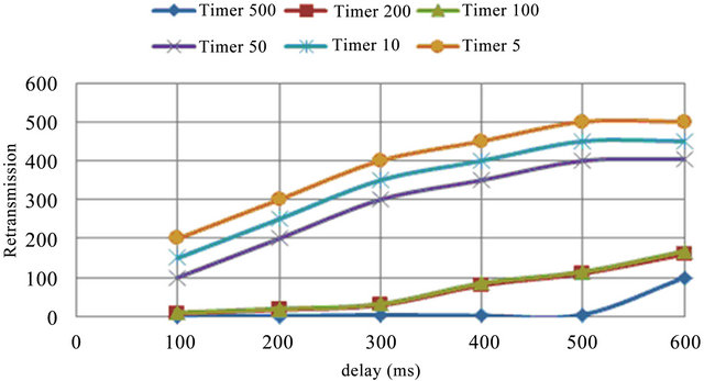
Figure 2. Chart of comparing the Invite message retransmission changes to different Delay changes for various values of Timer T1 changes in seconds.
network Delay has been considered in the minimum possibility. In these circumstances, by removing Delay effect, the Loss effect can solely been evaluated. therefore, the results obtained from this part of the tests carried only represent the SIP protocol behavior compared to Loss changes, In case of using UDP as a Transmission layer protocol and with respect to different values of Timer T1. This part of the experiment also has been carried in some separate stages and the results will be compared with each other. To do this, first UDP protocol has been set up as Transmission layer protocol, and then by changing the Loss applied, we conduct the test and study the amount of SST, Call drops, as well as the amount of Invite message retransmission. It should be noted that, for each amount of the Loss, different values of Timer T1 has been tested (see Figure 4).
It is necessary to note this point that Loss has not been by the simulation software and due to the network congestion, therefore, it should be considered similar to the circumstances that the messages have reached the target defectively. As it is specified in Figure 5, through analyzing Timer T1, which has also been mentioned before, it can be found that by reducing Timer T1, in a proper way, the effect of losing messages on the average time of a session initiation can be neutralized. It is obvious that
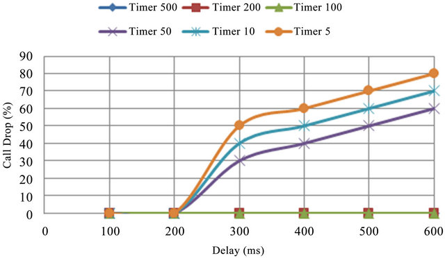
Figure 3. Chart of comparing the percentage of missed calls to Delay changes for different values of Timer T1 in milliseconds.
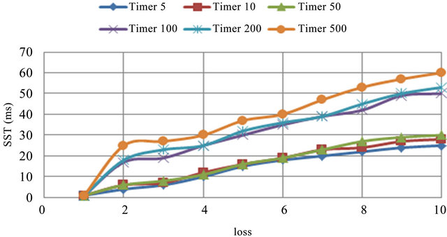
Figure 4. Chart comparing the average Session time set up to Loss change for different values of Timer T1 in milliseconds.
through rapid retransmission of Invite messages, the corrupted messages can immediately be compensated and it can cause the reduction of the average time of the session initiation.
Also through observing Figure 5, which represents the amount of Invite message retransmission, we can understand that by reducing the Timer the retransmission boosts and we can find out the point that since the network Delay is low (1 milliseconds) the amount of retransmission would be low and in the worst case (here Loss is equal to 10%) and the smallest selected Timer also does not set the amount of retransmission to 10%. So it has significant impact on the occupation of the bandwidth and on the other hand, it won’t have a lot of processing overload for UAS. It is necessary to mention that the rate of the contacts loss during this phase of the test is zero. It means that in the absence of so much Delay, Loss does not have a lot of impact on the loss of the contacts.
3.5. Study of the Rate of the Set up Calls
One of the other factors that can affect the session initiation time and can be effective in the Protocol result is the set-up contacts rate. The set-up contacts rate can be effective on the average time of set up contacts in various ways. Its first impact is on the communication bandwidth between two elements (UAC and UAS) i.e. If the limitation is on the bandwidth of the communication path between two Nods, the traffic and the load over the SIP messages causes creation of Congestion, on the other hand, it causes the increase of RTT and consequently, the increase of the necessary average time to initiate sessions and on the other hand, through the creation of the Packet loss the amount of retransmission will increase and as a result, by increasing the density, the efficiency of the Protocol will reduce more. The next effect of the contacts rate increase is to apply the resources in the server (here the UAS Nod). By noting resources we mean, process capacity and memory, which can result in effecting on processing speed and also increasing the time of wait
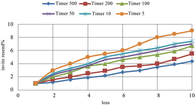
Figure 5. Chart comparing the changes of Invite message retransmission to the changes of the failed messages for different values for Timer T1 in milliseconds.
ing in the queue and thus increasing the time required to initiate the session and thus reducing the efficiency. Since in here, we just study the Delay rate of contacts, we have tried to set the other parameters including Packet loss and Delay in a way, so that there won’t be any interference in the results achieved. Therefore, the test environment has been selected in a way that the Packet loss is very minor and it is almost zero and the network delay is also about a millisecond.
This test has also been done in several stages, in a way that the rate of SST has been measured and evaluated with the rate of the load change. We should know that this test was repeated for different values of Timer T1, so that the effect of the Timer in different amounts of SIP traffic load can be evaluated in a more appropriate way. Figure 6 displays the average changes of the sessions’ initiation time to the load changes for different amounts of Timer T1. As it can be observed in the low amounts of Traffic load, Timer T1 does not have a noticeable effect on the average time of the session initiation, but the increase of the set up contacts rate has more effect on the Timer and it increases the session initiation average time in a greater degree, but in low amounts of the Timer the effect of the load is so much less. As it has been observed to reduce the negative effect of load increase, it is better that Timer T1 increases. Of course, it is in the conditions that the Delay rate is very low.
To consider the costs of this selection, we also evaluate the percentage of Invite messages retransmission. Figure 7 represents the retransmission changes to the Load changes for Timer T1 different amounts.
As it has also been anticipated, the small Timer will be a factor for more retransmission, which is also the same here. As it can be observed, in the range of the Traffic and selected Timers as much as 10 times increase of Timer T1, SST will be approximately 10 times, while the retransmission rate will be roughly half that will be indicative of the advantages of using smaller Timers in the conditions of Load increase.
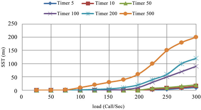
Figure 6. Chart of comparing the changes of the Session initiation time with Load changes for different values of Timer T1 in seconds.
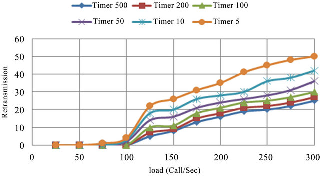
Figure 7. Chart of comparing the Invite message retransmission changes to load changes for Timer T1 different values in milliseconds.
4. Timer T1 Adaptive
As it has already been mentioned, Timer T1 specifies the initial values of Timer A as well as Timer B. Timer A has the task to retransmit Invite message and Timer B has the task of finishing the session in case a reply is not received. It seems, in order to have the Protocol performance to the best condition; we must perform the Invite message retransmission, in the best time, when the reply is not received from UAS. If the retransmission is done later than its time, it will result in increasing of the average time required to initiate a session and sooner than that, it might be in vain.
4.1. Detection of Invite Message Retransmission Time
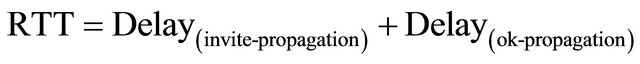
To determine the time required for waiting to get replies, we will analyze it. In this case, we should evaluate the time it takes to receive the reply, after transmitting the Invite message (which is called Delay (invite→ok)), therefore, we can obtain the time it takes to receive reply through the following total periods of time.
The period of time it takes that the Invite message UAC reaches UAS (it is called Delay(invite-propagation)).
The period of time it takes that Invite message is analyzed in UAS and temporary or final reply message is initiated. This time is the sum of all waiting periods of time in the queue and UAS processing (it is called Delay(Queuing/Processing)).
The period of time it takes, that the reply message (temporary or final) reaches from UAS to UAC (It is called Delay(Ok-Propagation)).
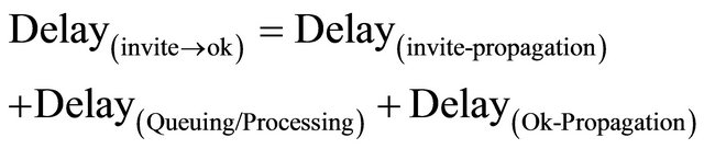 (3)
(3)
To determine the values of the above equation, we perform the following procedure:
1) To determine Delay(invite-propagation) + Delay(Ok-Propagation), we use Ping. With this estimation we can get the transmission and receiving time in the network or RTT. As we know the length of the transmitted packages in the network has effect during their sending and receiving and the larger length of the packages will cause the RTT time increase. To more appropriately estimate the Invite message transmission time and receiving the reply message it has been tried to use the Ping packages with a suitable length. According to [1] as average the Invite message length 728 Bytes and the OK message length is 573 Bytes. Therefore, the transmitted Ping packages length has selected as much as possible fit the SIP message length.
 (4)
(4)
2) To determine UAS processing time the following method is suggested:
First we describe one of the Protocol’s developments called Subscribe/Notify.
Subscribe/Notify Development
These two development methods are based on SIP that has been standard in RFC 3265. The general idea to create this development has been sending information from an event or a parameter change in an SIP element to another element. Subscribe is an SIP method. It means that it can be applied on an SIP request message. Notify can also be applied in a request message, although it is logically a reply.
The Subscribe sender element is called Subscriber and the Notify sender element is called the Notifier. Subscribe message usually contains the Expiration header, which indicates the length of time that the applicant demands to continue receiving the Notifying messages. After termination of this period of time, if the applicant is willing to continue receiving the Notify messages, he must register his request in the Notifier again. Generally we should know that Notifier includes information of an event or it is a change in a parameter, which knowing it is valuable for the subscriber and subscriber has requested them from Notifier, while registering his request.
In each Notify, which is sent to the applicant, the remaining time until the transmission termination has been registered and through using it, the applicant can take action to register his request again. In replying to each notify, the OK reply to confirm receiving from subscriber will be transmitted to the Notifier (Figure 8).
The frequency of Notify messages transmission is in this way, if a specified event occurs or if the required
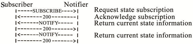
Figure 8. Subscribe/Notify development.
Parameter, which its information must be sent to the subscriber changes, the Notify message will be made immediately in the Notifier and will be sent towards the Subscriber. As the waiting in queue and the processing time in UAS Nod can be estimated and it is needed in UAC Nod, its estimation in UAC Nod encounters some problems (including getting the amount of free resources in UAS and estimating the amount of background load in it and …), the estimation and getting the time can be submitted to UAS. This means that in the UAS Nod, the time required creating the reply message for each Invite message request achieved and its average is maintained in the form of variable in UAS. It is obvious that the value of this variable according to the terms of the server and the method of averaging in different time intervals will change. Now, in order that the amount of this variable, which is the average processing time in UAS Nod, is applied for decision-making, one of the developments of the SIP protocol in the name of Subscribe/Notify is applied. As it has already been explained about this development of SIP, through it the amount of the abovementioned variable whenever changes, it will be sent to the UAC Nod through the Notify messages. Therefore, in the form of online the UAC Nod will be aware of the time of queuing and processing in the UAS Nod. This amount is called Delay(Queuing/Processing).
Generally, three conditions can be predicted for the transmitted Invite message:
1) Retransmission despite the existence of Delay in the network 2) Retransmission when the message is corrupted 3) Retransmission when Loss occurs We analyze each of them separately as follows and in each case we will obtain the appropriate value of Timer T1:
4.2. Retransmission Despite the Delay in Network
Now, with regard to the above contents and the use of the contents of (3) & (4), the following formula can be used to estimate the Delay in receiving the reply and the proper retransmission time:
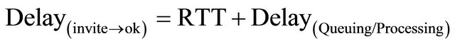 (5)
(5)
 (6)
(6)
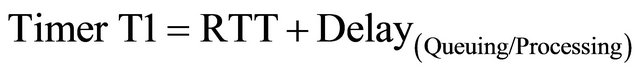
From the above-mentioned formula it can be realized that RTT and the time required for queuing and processing in UAS Nod, are the determiners for the Invite message retransmission time.
4.3. Retransmission When the Message is Corrupted
As we have already mentioned, in case any error is created in the Invite message (or temporary reply), the Invite message must be transmitted immediately. This means that in the event of a message malfunction, as soon as possible (possible minimum time) the message should be transmitted again. Therefore, to estimate the minimum time required to retransmit the following procedure should be done.
As we know, if the reply is not transmitted, the session will be terminated until the termination of Timer T1, and Timer B is 64 times more than Timer T1, so we can understand that Timer T1 can be  the time required for the reply to be received. That is, if Timer T1 is considered smaller than this amount, the session will be expired before receiving the reply, thus, the minimum time of the Timer is equivalent to the following formula:
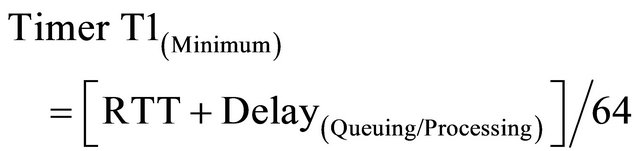 (7)
(7)
Therefore, retransmission, when the failure occurs can be obtained through the above formula.
4.4. Retransmission in the Event of Loss
We know, in case of the existence of congestion in the network, Loss will happen and it results in the loss of the packages. If the Invite message is lost (or the reply loss), the Invite message retransmission should be delayed and the congestion and the negative effects will be reduced through reducing the rate of the retransmission. For this reason, to estimate the time required for retransmission, here we have considered K coefficient (K > 1) for retransmission:
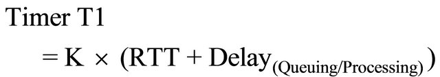 (8)
(8)
5. Estimating the Timer T1 Adaptive
As it is explained in the previous sections, 3 situations will occur for transmitted Invite message:
1) The received UAS message and its reply will also return.
2) The message or reply due to any reason is damaged on the track, so it cannot be applied.
3) The message or its reply due to the existence of congestion and Loss occurred in the network is lost.
Also for each state the appropriate amount of Timer T1 has been estimated. In order to be able to suggest the appropriate Timer, suitable weight should be related to each of the above components. The final amount of the Timer is the total above weight-given components.
Now, to have the percentage of the corrupted messages, the following procedure is done:
Therefore:
Therefore:
Therefore:

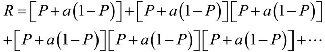
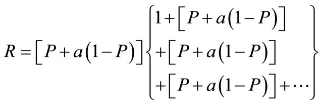
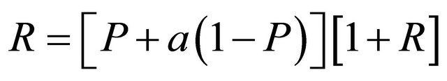
So the percentage of the defective messages is obtained from the formula (9):
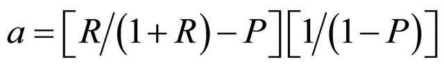 (9)
(9)
where P is the network Packet loss rate, (1-P) is the probability of the messages being reached, a is the percentage of the defective messages and R is the percentage of the retransmitted messages.
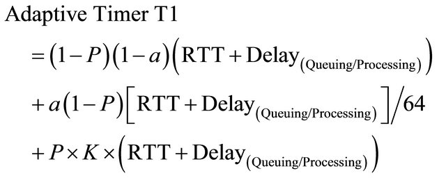
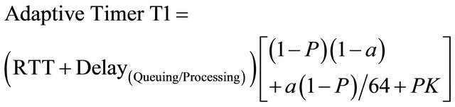
Now we considering (6) - (9) relations the proposed Adaptive Timer can be expressed as follows:
Therefore:
Therefore:
Therefore, we will have:
where K (1 < K) is called the Invite message retransmission rate reduction coefficient to reduce congestion.
6. Implementation of the Proposed Timer
In this section, to study the proposed accuracy performance of the Timer, through representing three different samples it will be reviewed.
1) Consider the circumstances that Loss = 5% and RTT = 600 ms and at the beginning, based on the default value of the Timer R is: R = 110%. Meanwhile, we have assumed the K coefficient 2. In these circumstances and on the basis of the proposed formula, the best time of the Timer T1, is specified approximately 700 milliseconds. Figures 9 and 10 respectively represent the SST changes and the percentage of retransmission packages to the Timer changes.
As it is observed, in the circumstances that Timer T1 is more than about 700 ms, it causes the increase of SST and there will not be great recovery and if it is less than 700 ms, it may reduce the SST, but it will greatly increases the invite message retransmission.
2) In this section, the proposed adaptive timer is compared with the fixed Timer and T1 default, which is equivalent to 500 milliseconds in the conditions that the network delay is 100 and the amount of the network loss is variable. Figures 11 and 12 respectively show the SST changes and the invite message retransmission in terms of Loss changes for the proposed fixed and adaptive Timer. As it is observed, the proposed formula shows appropriate improvement in SST. Of course, as it was anticipated, it also increases the amount of the message retransmission, which is very minor amount and it seems according to the rate of improvement, SST has appropriate effect on the SIP protocol efficiency.
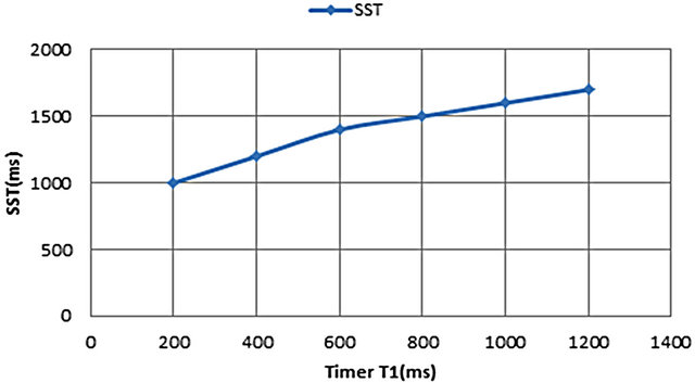
Figure 9. Chart of the session initiation time average changes to session Timer T1 in milliseconds.
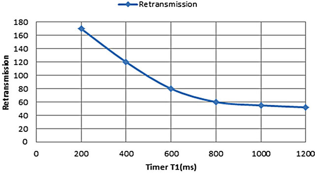
Figure 10. Chart of the Invite message retransmission changes to Timer T1 changes in terms of milliseconds.
3) In this section, the proposed adaptive Timer is compared with fixed Timer and Timer T1 default, which is the equivalent to 500 milliseconds in the circumstances, which the rate of conversation production has started from low amount and continues to heavy conversation rate up to 1800 contacts per second. Figure 13 shows the passage in the form of a function of the rate of incoming call requests in both cases, which indicates that despite the proposed adaptive timer, the proxy passage can be kept at the maximum capacity and this means to improve the performance, while facing with overload.
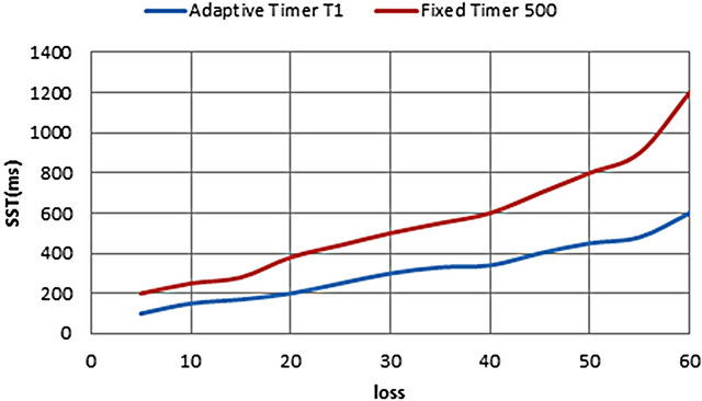
Figure 11. Chart of comparing the session initiation average time changes to loss changes in Adaptive Timer T1 and 500 milliseconds Fixed Timer.
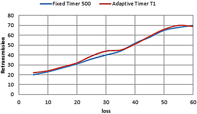
Figure 12. Chart comparing the Invite message retransmission changes to Loss changes in Adaptive and Fixed Timer T1.
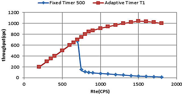
Figure 13. The throughput with Adaptive and Fixed Timer T1.
7. Conclusion
Considering the tests carried out, we can conclude, according to the amount of Loss and network delay as well as SIP traffic, the proper selection of Layer protocol can be effective in the time required for the session initiation and as a result the efficiency. Using TCP prevents any call drop, but it results in SST more time and the utilization of the bandwidth and CPU in the server and the cost of using UDP will be the existence of a slight call drop. In the conditions of the existence of Loss, using TCP is also optimal both in terms of SST and also in terms of call drop. Also, considering the experiments carried out, we have noticed the great effect of the appropriately regulating of Timer T1. As much as Timer T1 amount becomes smaller, the SST also reduces, but its cost is the increase of Invite message retransmission, which has a negative impact on the use of bandwidth and the CPU on the server. We should know that Timer T1 cannot be considered smaller than  time required to send the Invite message and receive a reply, because it will cause the sessions timeout. To make the SST time optimal (considering the amount of Invite message retransmission), Timer T1 must become larger, in the case of RTT increase, the time required for processing on the server increase and Loss increase and in case of the increase of the percentage of the messages malfunction, Timer T1 must become smaller. Meanwhile, the adaptive provided Timer, which was suggested with respect to the amount of Loss and Delay and messages malfunction, was evaluated and showed that to the proper extent, it has reduced the SST and it has not had a lot of negative impact on the message retransmission.
REFERENCES
- H. Fathi, S. S. Chakraborty and R. Prasad, “Optimization of SIP Session Setup Delay for VoIP in 3G Wireless Networks,” IEEE Transaction on Mobile Computing, Vol. 5, No. 9, 2006, pp. 1121-1132.
- E. Nahum, J. Tracey and C. P. Wright, “Evaluating SIP Server Performance,” Sigmetrics’07 Conference Proceedings, Vol. 35, No. 1, 2007, pp. 349-350.
- G. De Marco and G. Lacovoni, “A Technique to Analyse Session Initiation Protocol Traffic,” Proceedings of the 11th International Conference on Parallel and Distributed Systems, Vol. 2, 2005, pp. 595-599.
- R. Jain, V. K. Gurbani and R. Jain, “Transport Protocol Considerations for Session Initiation Protocol Networks,” Bell Lab Technical Journal, Vol. 9, No. 1, 2004, pp. 83- 97. doi:10.1002/bltj.20006
- N. Lindqvist, “SIP—Session Initiation Protocol,” Seminar on Instant Messaging and Presence Architectures in the Internet, 2005.
- H. Schulzrinne, S. Narayanan and J. Lennox, “SIPStone - Benchmarking SIP Server Performance,” Columbia University, Columbia, 2002
- D. Malas, “SIP End-to-End Performance Metrics,” 2007.
- B. Veena, M. L. Jagadeesan and K. G. Vijay, “Characterizing Session Initiation Protocol (SIP) Network Performance and Reliability,” Bell Laboratories, Lucent Technologies Naperville, Illinois, 2005.
- J. S. Rosenberg, “Session Initiation Protocol (SIP): Locating SIP Servers,” 2002.
- H. S. Rosenberg, “SIP: Session Initiation Protocol,” 2002.
- M. Cortes, J. O. Esteban and H. Jun, “Towards Stateless Core: Improving SIP Proxy Scalability,” 2006.