Journal of Electronics Cooling and Thermal Control
Vol.04 No.03(2014), Article ID:49373,10 pages
10.4236/jectc.2014.43007
Heat Transfer Characteristics of Square Micro Pin Fins under Natural Convection
Naoko Matsumoto, Toshio Tomimura, Yasushi Koito
Department of Advanced Mechanical Systems, Kumamoto University, Kumamoto, Japan
Email: 134d9211@st.kumamoto-u.ac.jp
Copyright © 2014 by authors and Scientific Research Publishing Inc.
This work is licensed under the Creative Commons Attribution International License (CC BY).
http://creativecommons.org/licenses/by/4.0/


Received 26 June 2014; revised 26 July 2014; accepted 27 August 2014
ABSTRACT
In order to comply with the recent demand for downsizing of the electric equipment, the minia- turization and the improvement in heat transfer performance of a heat sink under natural air-cooling are increasingly required. This paper describes the experimental and numerical investigations of heat sinks with miniature/micro pins and the effect of the pin size, pin height and the number of pins on heat transfer characteristics of heat sinks. Five types of basic heat sink models are investigated in this study. The whole heat transfer area of heat sinks having the different pin size, pin height and the number of pins respectively is kept constant. From a series of experiments and numerical analyses, it has been clarified that the heat sink temperature rises with increase in the number of pins. That is, the heat sink with miniaturized fine pins showed almost no effect on the heat transfer enhancement. This is because of the choking phenomenon occurred in the air space among the pin fins. Reflecting these results, it is confirmed that the heat transfer coefficient reduces with miniaturization of pins. Concerning the effects of the heat transfer area on the heat sink performance, almost the same tendency has been observed in other three series of large surface area, that is, higher pin height. Furthermore as a result of studying non-dimensional convection heat transfer performance, it was found that the relation between the Nusselt number (Nu) and the Rayleight number (Ra) is given by Nu = 0.16 Ra0.52.
Keywords:
Natural Air-Cooling, Heat Sink, Micro Pin Fin, Heat Transfer Performance, Experiment, Numerical Analysis

1. Introduction
In electronic equipment applications with high heat fluxes, the heat transfer performance and the lifetime of components are often deteriorated due to temperature rise. To avoid those unfavorable problems, it is necessary to keep the component under a critical temperature by introducing a high performance heat sink. Furthermore, in order to comply with the recent demand for downsizing of the electronic equipment, the miniaturization and the improvement in heat transfer performance of the heat sink are required much more strongly than ever. But it is well known that the decrease in heat transfer area by downsizing leads to a decline of the heat sink performance.
Many studies of heat transfer characteristics using large scaled heat sinks have been carried out so far. For example, Aihara et al. [1] and Sara [2] revealed that the heat sink performance depends on the pin size, the population density of pin. Zografos and Sunderland [3] studied the effect of pin arrangement on the heat transfer performance, and reported that a choking phenomenon, which had a negative effect on heat transfer from a heat sink, was observed in the air space among pin fins. Huang et al. [4] , Sparrow et al. [5] and Sertkaya et al. [6] investigated experimentally the dependence of the pin fin performance on a heat sink orientation.
In electronic equipment applications, heat sinks are placed within enclosed areas and the emphasis is on making the enclosures more compact than ever. Yu et al. [7] and Bocu et al. [8] reported natural convection heat transfer from heat sink attached to enclosures in their studies.
On the other hand, concerning small sized heat sinks or nano particles structure, the analytical and experimental studies were published by Narasimhan et al. [9] and Minakami et al. [10] , Kunugi et al. [11] . Although interesting findings on natural and forced convection, and radiation from heat sinks have been reported in the previous studies, the mechanism of the heat transfer has not been clarified yet.
Accordingly, in the present study, the effects of pin size, pin height and the number of pins on the heat transfer characteristics of heat sinks with miniature/micro pins have been investigated fundamentally.
2. Heat Sink Models
Five types of basic heat sink models are shown in Figure 1. The first model has four square pins, and is named as Type 1. Each pin placed at equal space of the heat sink base (length: 25 mm, width: 25 mm, thickness: 2 mm) has the pin width wp = 6.25 mm and the pin height hp = 6.5, 14, 21.5, 29 mm at intervals of 7.5 mm. And in Type 2 model, the pin size is reduced to half the pin width and height of Type 1. That is, under the conditions of constant heat transfer area, the number of pins for Type 2 is quadrupled against Type 1. In the same manner, five types of heat sinks in total, which have the pin height from several hundred micro meters to a few millimetres and have the same heat transfer area, are prepared.
As listed in Table 1, the number of pins N is changed from 4 to 1024, and corresponding to this change in N, the pin width wp and the pin height hp vary from 0.39 mm to 6.25 mm and from 0.41 mm to 29 mm, respectively. The whole heat transfer area of the square pin series Ahs is 1.48 ´ 10−3 m2, 2.23 ´ 10−3 m2, 2.98 ´ 10−3 m2 and 3.73 ´ 10−3 m2.

Figure 1. Heat sink models, (a) Top view, (b) Side view, (c) Parts and nomenclature.

Table 1. Dimensions of pin fin.
3. Experimental
Figure 2 shows a schematic diagram of experimental apparatus, which consists of a chamber, a vacuum pump, a vacuum gauge, and a heat sink with a heater used as the heat source. The chamber made of SUS is 400 mm in diameter and 170 mm in height. Here, its wall temperature which is regarded as the ambient temperature Ta was kept at 25˚C by circulating cooling water. The heat sink was hung in the air in the chamber by using fine wires to reduce the heat loss from the heat sink to the chamber wall by conduction. The heat sink was placed in the upward facings of the heated surface. The pressure in the chamber was controlled with the vacuum pump from the atmospheric pressure to the vacuum condition of approximately 3.5 × 10⁻² Pa, and the chamber pressure was measured using the vacuum gauge. Under the atmospheric pressure, heat is transferred from the heat sink to the surroundings by convection and thermal radiation. On the other hand, under the vacuum condition of approximately 3.5 × 10⁻² Pa, heat is transferred from the heat sink to the surrounding wall only by thermal radiation.
As shown in Figure 3, the heat sink, which is made of Aluminum alloy A6063 (the thermal conductivity l = 200 W/(m∙K), the emissivity e = 0.89) with a base plate of 25 mm long, 25 mm wide and 2 mm thick, was placed on the same sized square copper block (thickness: 2 mm, l = 398 W/(m∙K)) through a thermal interface material (thickness: 0.5 mm, l = 3.1 W/(m∙K)). Furthermore, on the bottom part of the copper block, a ceramic heater is attached through the thermal interface material. The representative temperature Th was measured using a f 0.5 mm K-type thermocouple fixed in a small groove machined at the copper block center. In Figure 3, Ta is the ambient temperature.
First, under the atmospheric pressure, the heat rate Qin = 1.25 W was applied to the heat sink by the ceramic heater. Second, the representative temperature Th was measured under the steady-state condition. Third, under the vacuum condition of approximately 3.5 × 10⁻² Pa, some amount of heat was applied to the heat sink by the heater until the heat sink temperature became the same temperature Th under the atmospheric pressure, and then the heat transferred by thermal radiation Qr from the heat sink under the steady-state conditions was measured based on the input power to the heater. Furthermore, in the same manner, Th and Qr for the heat sink consisting only of the base plate were also measured for reference.
4. Numerical Analysis
Figure 4 shows the boundary conditions for the large air space surrounding the heat sink placed in the upward facings of the heated surface. A series of numerical analyses have been performed for the physical models shown in Figure 1 and for the heat sink consisting only of the base plate (25 mm, 50 mm, 100 mm and 150 mm on a side) for reference. In this study, the fine wires for hanging the heat sink and the copper block, the thermal interface material were neglected for simplification, and only the heater (length: 25 mm, width: 25 mm, thickness: 0.5 mm), the heat sink, and the surrounding large air space were taken into consideration.
The present numerical calculations were carried out using the simulation software of Computational Fluid Dynamics (CFD). The following assumptions are applied in the analysis.
1) Fluid is incompressible.
2) Thermophysical properties are assumed to be constant except density (Boussinesq approximation).
3) Ambient temperature Ta is constant.
Based on these assumptions, the following basic equations are obtained under the steady state conditions.
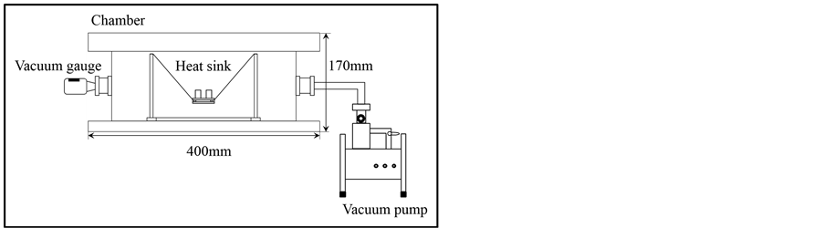
Figure 2. Schematic of experimental apparatus.

Figure 3. Configuration of tested heat sink.

Figure 4. Boundary conditions of CFD (upward facing).
Continuity equation:
 (1)
(1)
Momentum equations:
 (x-direction) (2)
 (y-direction) (3)
 (z-direction) (4)
Energy equation:
 (5)
(5)
Boundary conditions are given as follows. The same heat rate Qin = 1.25 W as the experiment was applied to the heat sink. The velocity is zero on all the solid surfaces, that is u = v = w = 0. The gauge pressure pg of the inlet and the outlet of the large surrounding space is 0 Pa, the inlet air temperature is 25˚C, and other remaining surfaces are adiabatic. The amount of heat transfer rate by convection and thermal radiation is equal to that by conduction through the solid.
The equation of conduction within the solid is given by the following equation.
 (6)
(6)
In the numerical analysis, the same heat rate Qin = 1.25 W as the experiment was applied to the heater. In the case of large sized heat sink consisting only of the base plate, the heat rate added to the base plate was kept constant.
Then the representative temperature Th of the heat sink under the steady-state conditions and the heat rate released from the heat sink by thermal radiation Qr were calculated using the simulation software of CFD. In addition, the velocity vectors and the temperature fields at the central lateral plane of the heat sink were obtained.
5. Results and Discussion
5.1. Heat Transfer Performance of Heat Sinks
Figure 5 and Figure 6 show the measured and simulated results on the effects of the number of pins N, the pin height hp on the temperature rise DT of the heat sink. Here, DT is defined as the difference between the repre-

Figure 5. Effects of N and hp on DT (measured results).

Figure 6. Effects of N and hp on DT (calculated results).
sentative temperature Th and the ambient temperature Ta. Accordingly, the lower DT means a higher heat transfer performance. The symbols show the results for the heat sink with different pin height, that is, heat transfer area. The broken line shows the DT for the heat sink consisting only of the base plate. Further, the number of pins N corresponds to the heat sink type from Type 1 to Type 5.
Concerning Type 1 model having the smallest number of pins, it is found that the heat sink performance of Type 1 model is the highest and as the pin height hp is higher, the heat sink performance is better. In a series of heat sinks, the heat transfer rate increases with the pin height of Type 1. Each representative temperature Th of the heat sink rises with increase in the number of pins N. Especially, in the case of large N, the temperature rise DT of the heat sink comes close to that of the base plate level. In other words, the heat sink with miniaturized pins has almost no effect on the heat transfer enhancement. As seen from the figure, the simulated results agree qualitatively well with the measured results. That is, the dependence of the temperature rise DT on the number of pins N agrees fairly well with each other. Unfortunately, however, a quantitative agreement is not obtained between them. This is because the present physical model cannot reproduce the experimental heat sink system exactly.
5.2. Velocity Vector and Temperature Field
The velocity vector in air space surrounding the heat sink model at central longitudinal section, which are obtained from numerical simulation, are shown in Figure 7. From this figure, it can be seen that the velocity vector among pins becomes small with increase in the number of pins. In particular, the air velocity of Type 5 models becomes almost zero.
The temperature fields of the heat sink and its surrounding air space are shown in Figure 8. The representative temperature Th at the heater surface is the highest. From this figure, it can be seen that the heater tem- perature rises from Type 1 to Type 5. Namely, this means that the increase in the number of pins causes the

Figure 7. Flow field along center line of heat sink; (a) hp = 6.5 mm, (b) hp = 29 mm series.
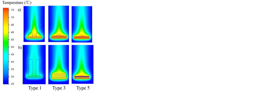
Figure 8. Temperature field along center line of heat sink; (a) hp = 6.5 mm, (b) hp = 29 mm series.
deterioration of the heat sink performance.
5.3. Air Velocity between Pins
Figure 9 shows the air velocity between pins which was numerically obtained for Type 1 to Type 5 models. The present air velocity means the average value obtained at central lateral plane of heat sink. As shown in the figure, the air velocity decreases with increase in the number of pins. This result shows the same tendency as the velocity vectors. In Type 3 to Type 5 models, regardless of the pin height, the air velocity becomes almost zero. This behavior must be the choking phenomena observed in the previous study using the large sized heat sinks done by Zografos et al. [3] , and as an inevitable consequence, it leads to low heat transfer performance of the heat sink.
5.4. The Ratio of Convective and Radiative Heat Transfer Rates
In order to estimate the heat sink performance from the view point of the heat transfer, the ratio of convective and radiative heat transfer rates in whole heat sink system has been also investigated experimentally and analytically, and the measured and calculated results are shown in Figure 10 and Figure 11 respectively. The total amount of heat transfer rate into and out has to keep the energy balance expressed by Equation (7). Under the conditions of the experiments and numerical calculations, Qin is 1.25 W. In addition, the output energy from heat sink is the sum of convective and radiative heat transfer rates Qc and Qr, so the amount of heat transferred by convection Qc is given by the following Equation (8).
 (7)
(7)
 (8)
(8)

Figure 9. Flow velocity between pins on heat sink.
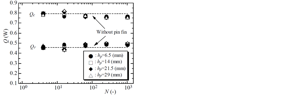
Figure 10. Effects of N and hp on Q (measured results).

Figure 11. Effects of N and hp on Q (calculated results).
As seen from Figure 10, it is clear that the convective component Qc which is the dominant parameter in this case attains its maximum by Type 2, and reduces to Type 5 and then becomes saturated. It can be observed that the convection component Qc of Type 2 is exactly proportional to the pin height hp, in other words the heat rate transferred by thermal radiation Qr vary inversely proportional to the pin height hp. And in other heat sink models there is no correlation between the convection component Qc and the pin height hp. Furthermore, the heat rate transferred by convection Qc occupies approximately 60% of the total input or output energy Qin or Qout, the heat rate transferred by thermal radiation Qr is about 40%, and the result agrees very well with the results reported by Sparrow et al. [5] . And from Figure 11, it is found that the calculated results agree well with the measured results qualitatively. However a quantitative agreement is not obtained between them, as previously noted, this is because the present physical model cannot reproduce the experimental heat sink system exactly.
5.5. Heat Transfer of Heat Sink under Natural Convection
In numerical simulations, the total amount of heat transfer rates of the heater and the heat sink was investigated. The convective component of heat sink only is represented by Equation (9) using computable parameters of the total amount of convective heat transfer rate Qc and the heat transfer from heater by convection Qc_ht.
 (9)
(9)
The convective heat transfer rate of the heater is calculated by Equation (10),
 (10)
(10)
 (11)
(11)
where Nu is the Nusselt number, la is thermal conductivity of air, L is characteristic dimension and A is heat transfer surface of the heater. Equation (11) gives the heat transfer coefficient h.
It is found that the heater has isothermal heating surface according to the simulated results, the Nusselt numbers at the lower and side surfaces of the heater are calculated by previously-proposed Equation (12) [12] , Equation (13) [13] and Equation (14), where Nu1 is the Nusselt number of lower surface of heated plate, Nu2 is that of vertical surface of heated plate. And Ra is the Rayleigh number which is represented as the correlation parameter between the Grashof number and the Prandtl number.
 (12)
(12)
 (13)
(13)
where
 (14)
(14)
Two types of characteristic lengths L will be employed here. In the case of the lower surface of cooled plate, L is taken as L = A/P where A is the plate surface area and P is the perimeter which surrounds the area [14] . In the vertical flat plate, L is taken as 0.5 mm which is the height of heater. Using these numbers, Qc_ht of the each side is calculated by substituting Nu1 and Nu2 into Equation (10). And then Qc_hs is determined by Equation (9) using known Qc.
Figure 12 shows the effects of the number of pins and the pin height on the convective heat transfer coefficient. Here, in order to evaluate the improvement in the convective heat transfer performance for heat sink base surface, the surface area of the top of the base is adopted as A (6.25 × 10⁻⁴ m2 constant). In this figure, it is clear that each heat transfer coefficient h of the heat sink decreases with increase in the number of pins N and in the case of Type 5 model it comes close to that of the base plate level. Since Figure 12 agrees well with the results of the temperature rise, it is considered that the factor of decreasing heat transfer performance due to the miniaturization is the convective heat transfer coefficient.
Finally, the calculated data of heat sink, expressed in terms of Nu and Ra, are plotted in Figure 13. In this figure, the lower solid line represents Equation (15) [14] in which Nu3 is the Nusselt number of upper surface of heated plate and the symbols (´) show the calculated results of the base plate.
 (15)
(15)
From these results, it is confirmed that Equation (15) applied to a range of the low-Rayleigh number. Using Equation (11), the Nusselt number of the heat sinks was calculated. Here, L was estimated to be the total value of the pin height hp and the base height 2 mm. As seen this figure, regardless of the pin size, the pin height, the number of pins, it is revealed that Nu and Ra of the heat sink are expressed by an approximate equation, such as Equation (16).
 (16)
(16)
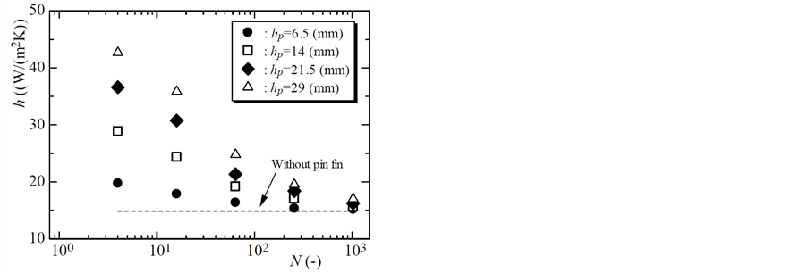
Figure 12. Effects of N and hp on h (calculated results).
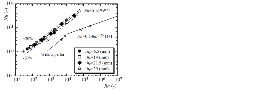
Figure 13. Correlation of Ra and Nu of the heat sink based on the base plate.
Since the calculated results were shown between ±20% of the approximate expression and with miniaturization of pins the Nusselt number Nu of the heat sink comes close to that of the base plate level, it is considered that the proposed correlation implies high accuracy.
6. Conclusions
In this study, experimental and numerical studies have been done on the effects of the pin size, pin height, the number of pins on the heat transfer performance of the heat sink.
Concerning the heat sinks with the same heat transfer area, it has been confirmed that the heat sink performance changes depending on the population density of pin and the pin size. From the measured and calculated results, the heat sink temperature has been shown to rise with increase in the number of pins. Especially, the heat sink with miniaturized pins has almost no effect on the heat transfer enhancement. It is considered that these characteristics of the heat sink cause the decrease in the convective component, which occupies approximately 60% of total heat transfer rate, and the heat transfer coefficient due to the decrease in the flow velocity when the pin to pin clearances are reduced.
Regardless of the pin size, the pin height, and the number of pins, it has been revealed that the Nusselt number and the Reyleigh number of the heat sink are represented by an approximate equation.
References
- Aihara, T., Maruyama, S. and Kobayakawa, S. (1990) Free Convective/Radiative Heat Transfer from Pin Fin Arrays with a Vertical Base Plate (General Representation of Heat Transfer Performance). International Journal of Heat Mass Transfer, 33, 1223-1232. http://dx.doi.org/10.1016/0017-9310(90)90253-Q
- Sara, O.N. (2003) Performance Analysis of Rectangular Ducts with Staggered Square Pin Fins. Energy Conversion and Management, 44, 1787-1803. http://dx.doi.org/10.1016/S0196-8904(02)00185-1
- Zografos, A.I. and Sunderland, J.E. (1990) Natural Convection from Pin Fin Arrays. Experimental Thermal and Fluid Science, 3, 440-449. http://dx.doi.org/10.1016/0894-1777(90)90042-6
- Huang, R.T., Sheu, W.J. and Wang, C.C. (2008) Orientation Effect on Natural Convective Performance of Square Pin Fin Heat Sinks. International Journal of Heat and Mass Transfer, 51, 2368-2376. http://dx.doi.org/10.1016/j.ijheatmasstransfer.2007.08.014
- Sparrow, E.M. and Vemuri, S.B. (1986) Orientation Effects on Natural Convection/Radiation Heat Transfer from Pin- Fin Arrays. International Journal of Heat and Mass Transfer, 29, 359-368. http://dx.doi.org/10.1016/0017-9310(86)90206-1
- Sertkaya, A.A., Bilir, S. and Kargici, S. (2011) Experimental Investigation of the Effects of Orientation Angle on Heat Transfer Performance of Pin-Finned Surfaces in Natural Convection. Energy, 36, 1513-1517. http://dx.doi.org/10.1016/j.energy.2011.01.014
- Yu, E. and Joshi, Y. (2002) Heat Transfer Enhancement from Enclosed Discrete Components Using Pin-Fin Heat Sinks. International Journal of Heat and Mass Transfer, 45, 4957-4966. http://dx.doi.org/10.1016/S0017-9310(02)00200-4
- Bocu, Z. and Altac, Z. (2011) Laminar Natural Convection Heat Transfer and Air Flow in Three-Dimensional Rectangular Enclosures with Pin Arrays Attached to Hot Wall. Applied Thermal Engineering, 31, 3189-3195. http://dx.doi.org/10.1016/j.applthermaleng.2011.05.045
- Narasimhan, S. and Majdalani, J. (2002) Characterization of Compact Heat Sink Models in Natural Convection. IEEE Transactions on Components and Packaging Technologies, 25, 78-87. http://dx.doi.org/10.1109/6144.991179
- Minakami, K., Mochisuki, S., Murata, A., Yagi, Y. and Iwasaki, H. (1993) Heat Transfer Characteristics of Pin-Fins with In-Line Arrangement (1st Report, Effect of the Pin Pitch). Japan Society of Mechanical Engineers, 59, 300-307.
- Kunugi, T., Muko, K. and Shibahara, M. (2004) Ultrahigh Heat Transfer Enhancement Using Nano-Porous Layer. Superlattices and Microstructures, 35, 531-542. http://dx.doi.org/10.1016/j.spmi.2004.04.002
- Kreith, F. and Bohn, M.S. (2000) Principles of Heat Transfer. 6th Edition, Brooks/Cole.
- Nakayama, A. (2008) Problems in Heat Transfer. Japan Society of Mechanical Engineers. Maruzen Publishing Co., Ltd.
- Goldstein, R.J. and Sparrow, E.M. (1973) Natural Convection Mass Transfer Adjacent to Horizontal Plates. International Journal of Heat and Mass Transfer, 16, 1025-1035. http://dx.doi.org/10.1016/0017-9310(73)90041-0
Nomenclatures
A: heat transfer area (m2);
cp: specific heat (J/(kg×K));
Gr: Grashof number (−);
g: gravitational acceleration (m/s2);
h: heat transfer coefficient (W/(m2×K));
hp: height of pin (mm);
L: characteristic length (m);
N: number of pins (−);
Nu: Nusselt number (−);
P: perimeter (m);
Pr: Prandle number (−);
p: pressure (Pa);
Q: heat transfer rate (W);
Ra: Rayleigh number (−);
T: temperature (˚C or K);
u: velocity component in x-direction (m/s);
V: air velocity (m/s);
v: velocity component in y-direction (m/s);
w: velocity component in z-direction (m/s);
wp: width of pin (mm).
Greek Symbols
α: thermal diffusivity (m2/s);
b: coefficient of volume expansion (K−1);
e: emissivity (−);
ΔT: temperature difference (˚C or K);
λ: thermal conductivity (W/(m×K));
υ: kinematic viscosity (m2/s);
ρ: density (kg/m3).
Subscripts
a: ambient or air;
c: convection;
g: gauge;
h: representative;
ht: heater;
hs: heat sink;
in: input;
out: output;
r: radiation;
1: lower surface of heated plate;
2: vertical surface of heated plate;
3: upper surface of heated plate.