Open Journal of Inorganic Chemistry
Vol.07 No.01(2017), Article ID:72973,15 pages
10.4236/ojic.2017.71001
A Simple and “Green” Method for Synthesis of Magnetic Hollow Silica Spheres and Its 99Tcm Labeled Targeting Studies
Yicheng Liu1, Xiazhang Li2, Jen Sloppy3, Yan Huang1*, Pingping Yao1, Junya Yang1, Yuxiang Yang1*
1School of Chemistry and Molecular Engineering, East China University of Science and Technology, Shanghai, China
2School of petrochemical engineering, Changzhou University, Changzhou, China
3Department of Materials Science and Engineering, University of Delaware, Newark, DE, USA

Copyright © 2017 by authors and Scientific Research Publishing Inc.
This work is licensed under the Creative Commons Attribution International License (CC BY 4.0).
http://creativecommons.org/licenses/by/4.0/


Received: October 9, 2016; Accepted: December 20, 2016; Published: December 23, 2016
ABSTRACT
The magnetic hollow silica spheres (MHSS) with uniform cavity size and shell thickness were prepared by a simple and “green” method using functionalized SiO2 spheres as templates. Magnetic particles (Fe3O4) were deposited on the SiO2 surface by varying the molar ratio of [Fe2+]/[Fe3+] and the molar concentration of iron salts. The obtained magnetic hollow silica spheres exhibited a super-paramagnetic behavior at room temperature. Scanning electron microscopy (SEM), transmission electron microscopy (TEM), and X-ray powder scattering (XRD) were applied to characterize the MHSS. Besides, their unit cell parameters are calculated according to results indexing to XRD, the MHSS sample prepared at 0.10 M iron salts and 2:1 molar ratio of [Fe2+]/[Fe3+] has a largest cell angle (β) of unit cell. Due to large hollow cavity space and super-paramagnetic characteristics, the inner amino-functionalized MHSS could be labeled with radioisotope 99Tcm to study the MHSS’s magnetic targeting distribution in vivo. These results indicate that the MHSS has potential in the magnetic targeted drug delivery system which reduces the damage to normal cells and improves the therapeutic effect of cancer.
Keywords:
A Simple and “Green” Method, Magnetic Hollow Silica Spheres, Magnetic Targeting, Iron Salts, Radioisotope 99Tcm

1. Introduction
Hollow magnetic silica spheres (MHSS) have received great attention in many fields including catalysts [1] [2] , microwave absorbing material [3] , drug carriers [4] [5] [6] and the immobility of biomolecules [7] [8] [9] , due to their unique properties such as low toxicity, biocompatibility, high specific surface area and huge interior space, which could provide greater drug loading volume and better adsorption ability compared to conventional mesoporous silica materials.
To date, a variety of methods (such as layer-by-layer coating technology [1] [10] , spray pyrolysis [11] , precipitation [12] ) have been invented and employed to fabricate hollow spheres. Zhu et al. prepared the rattle-like Fe3O4@SiO2 hollow mesoporous spheres using the carbon spheres absorbed with iron precursor as the templates [13] . Frank Caruso et al. fabricated MHSS by coating anionic polystyrene latices with Fe3O4 nanoparticle layers alternately adsorbed with polyelectrolyte from aqueous solution [14] . Shi’s group prepared for the MHSS through sol-gel reactions followed by hydrothermal treatment and H2 reduction [15] . However, the synthetic procedures are rather complex, and the hollow spheres surface are difficult to be functionalized.
Normally, two strategies have been established to obtain functional hollow mesoporous spheres. One is that the inner and outer walls of the hollow microspheres are functionalized. For example, Darya Radziuk reported the synthesis of silver nanoparticles for remote opening of polyelectrolyte microcapsules [16] . The other is that functional microspheres are placed in the cavity of the hollow microspheres. Caruso’s group [17] demonstrated that a new concept for the immobilization of enzymes using inner functionalized hollow microspheres, which displayed improved enantioselectivity in a given reaction. In addition, hollow mesoporous spheres were prepared by polyelectrolyte almost have semi-permeable, so the small-molecule solvent, vitamin B12, dye or ions can penetrate through which is conducive to small-molecule drug sustained release.
In this paper, we reported an efficient route to prepare MHSS using the sulfonated SiO2 spheres as the hard templates by a simple and “green” method using co-precipitation route. The schematic procedure for the preparation of magnetic hollow spheres is shown in Figure 1. Thiol groups of the hollow silica spheres are oxidized as sulfonic acid groups by hydrogen peroxide, and then silica/Fe3O4 hollow spheres are prepared
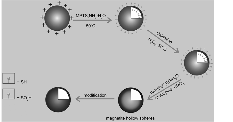
Figure 1. Schematic procedure for the preparation of magnetic hollow spheres.
using sulfonic acid-functionalized hollow silicaspheres as templates. The inner amino- functionalzied MHSS were labeled with radioisotope 99Tcm to study the MHSS’s magnetic targeting distribution in vivo.
2. Experimental Section
2.1. Materials
All reagents used were analytical grade and available commercially. Styrene, FeCl3・6H2O, FeCl2・7H2O, KNO3, hydrogen peroxide (30 wt%), and aqueous ammonia solution (28 wt%) were purchased from Shanghai Lingfeng Chemical Reagent Co., Ltd., (China). 2,2’-Azobis (2-methylpropi-onamidine) dihydrochloride (AAPH), polyvinylpyrrolidone (PVP, Mw = 30000), 3-aminopropyl triethoxy-silane (APTES), Hexamethylenetetramine (HMT), and 3-mercaptopropyltriethoxysilane (MPTS) purchased from Sigma-Aldrich Co. The aforementioned chemicals were used as received.
2.2. Preparation of Thiol-Functionalized Hollow Silica Spheres (THSS)
3.0 g of styrene, 1.5 g of PVP and 0.39 g of AAPH were dissolved in 100 mL of deionized water, and then the mixture was maintained at 70˚C in nitrogen atmosphere. After stirring for 24 h, the polystyrene emulsion was filtered by micro-pore film filter andplaced at room temperature for 2 days. Then, 40 mL of ethanol, 5 mL of aqueous ammonia and 1.0 g of 3-mercaptopropyltriethoxysilane (MPTS) were added into polystyrene emulsion, this solution under vigorous stirring was heated up to the temperature of 50˚C for 4 h. Then the product was separated by centrifugal hydroextractor, following washed with deionized water three to four times and ethanol two times. The thiol-functionalized hollow silica spheres (THSS) were prepared.
2.3. Preparation of Sulfonated Hollow Silica Spheres (SHSS)
The as prepared THSS (0.8 g) were dissolved into 30 wt% 32 mL hydrogen peroxide, and kept the oxidation reaction at 50˚C for 12 h under a constant stirring at 300 rpm. The obtained sulfonated hollow silica spheres were separated again by centrifugation, following washed with deionized water three to four times and ethanol two times. Finally, the SHSS were re-dispersed into deionized water.
2.4. Preparation of MHSS and Amino-Functionalized MHSS
First, 0.3 g of freeze-dried sulfonated SiO2 template spheres were dispersed in a solution composed of 50 mL ethanediol and 50mldeionized water. Next, 2.0 g of Hexamethylenetetramine (HMT) and 0.2 g of potassium nitrate (KNO3) were added with stirring for 30min, then 20 mL 0.05 M iron salts (Fe3+, Fe2+) was added to the reaction mixture under vigorous stirring and subsequtently heated at 80˚C for 5 h. The obtained magnetic hollow spheres were purified by centrifugation and dried under vacuum at ambient temperature. With all of the other parameters being kept constant, the iron salts concentration, and the molar ratio of [Fe2+]/[Fe3+] were varied to evaluate their effects on the morphologies of MHSS. Table 1 summarized the nomenclatures we used for products adopting iron salts concentrations and different molar ratio of [Fe2+]/[Fe3+].
The dried MHSS were re-suspended in the dried toluene (50 ml), followed by the

Table 1. The nomenclatures of the samples adopting different molar ratio of [Fe2+]/[Fe3+] and iron salts concentrations.
addition of 3-aminopropyl triethoxysilane (APTES, 1 ml); the mixture was then heated to reflux for 12 h. The amino-functionalized magnetic MHSS were separated by a magnet and washed with ethanol and water, and then dried for 12 h.
2.5. Preparation of 99mTc Labeled MHSS and Biodistribution
The  was reduced using stannous chloride, typically, 8 mg of SnCl2, 0.1 ml of 0.5 mol/L sodium gluconate solution, 0.4 ml of PBS (pH = 5.7), and 5 mg of unlabeled compound (MHSS-a) (amino-functionalized-MHSS) were mixed in the vial to form homogeneous solution, which were subjected to ultrasonic treatment for 15 min. Then 1ml of 5 mCi/ml
  eluate was added, the mixture was heated to 70˚C for 2 h, the labeled compound (MHSS-99mTc) were separated by magnetic field and washed with deionized water, and the radiochemical purity of the labeled compound was checked with Capintec CRC-15R external dose calibrator.
To further investigate the biodistribution of nanoparticles, 0.5 mCi/1ml 99Tcm labelled MHSS solution were injected into the female mice via caudal vein. After a certain time in magnetically targeted therapy, the animals were sacrificed with an overdose of sodium pentobarbital, and the main organs (the blood, heart, lung, liver, spleen, pancreas, stomach, small intestine, large intestine, brain, muscle and bone) were detached and weighed. The main organs were rinsed with buffer and remaining cell-associated radioactivity was measured with a γ-counter respectively.
2.6. Characterization
A Hitachi S-4800 field emission scanning electron microscope (SEM) and a PhilipsTecnai-12transmission electron microscope (TEM) were used to characterize the morphology of the products. The infrared spectra were recorded by a Nicolet Impact 410FT-IR using KBr disks. X-Ray Powder Diffraction (XRD) was used to characterize the crystalline phases of the materials. A vibrating-sample magnetomer (VSM JDM-13) was used to characterize the magnetic properties.
3 Results and Discussion
3.1. The Structure and Morphology of THSS
As shown in Figure 2(a), Figure 2(b), it can be seen that the THSS spheres have clear cavity, and uniform size. The particle sizes of the samples are approximately 100 nm diameters, and the shell thickness is about 15 nm and the core diameter is about 75 nm. The SEM image recorded in Figure 2(c) clearly exhibited a uniform spheres structure with diameters and the sizes are close to the TEM results.
FTIR measurements can be used to deduce the surface properties of materials. Figure 2(d) illustrates the FTIR spectra of THSS samples. The peak at 2555 cm−1 is attributed to the stretching vibrations of S-H, the peaks at 698 cm−1 and 753 cm−1 are attributed to the stretching vibration of the monoreplacement in the phenyl ring group of samples, and the peak at 1035 cm−1 is attributed to the vibration of Si-O-Si. Similarly, two peaks at 1641 cm−1 and 3435 cm−1 are assigned to the O-H bond. These findings indicate that the mercapto group is presented in THSS.
Nano SiO2 can be successfully coated on the surface of polystyrene because of the mutual interaction between positive charged polystyrene and negative charged MPTS, which may be hydrolyzed into SiO2 carried thiol group under catalysis by ammonia. Therefore, the formation process of hollow silica spheres was related to ammonia, which not only served as a reactant to form SiO2, but also as an alkali media to “dissolve” PS template spheres with ethanol [18] [19] . This method is a simple and “green” method to remove any templates of polystyrene cores in synthesis process which need not any additional dissolution, calcination, and etching process.
3.2. The Structure and Morphology of SHSS
The TEM images of as-synthesized SHSS are illustrated in Figure 3(a) and Figure 3(b). The TEM observation indicates that as synthesized SHSS exhibiting hollow structure. The average size is around 100 nm, with the hollow diameter of 75 nm and the silica shell of 15 nm. Some shells of SiO2 were linked among the particles (Figure 3(b)),

Figure 2. (a)-(b) TEM images, (c) SEM images and (d) FTIR spectra of THSS samples.
because SiO2 formed by MPTS hydrolysis were the reunion of Si-O-Si. The morphology of the obtained SHSS recorded in Figure 3(c) exhibits uniform spherical shape with the size of 100 nm. Figure 3(d) displays FTIR spectroscopy of as-synthesized SHSS structure, in which the structural change of hollow silica spheres can be observed. The absorption peaks around 698 and 753 cm−1 are attributed to the phenyl group, and the peak at 1035cm−1 is assigned to the vibration of Si-O-Si. The pair peaks at 1641 cm−1 and 3435 cm−1 are assigned to the O-H bond. In addition, the peak at 2555 cm−1 has vanished in comparison to Figure 2(d), but appearance of a new peak at 1450 cm−1 can be attributed to the absorption peaks of sulfonic group, indicating mercapto group (S-H) has been oxidized to sulfonic groups.
3.3. The Structure and Morphology of MHSS by Varying the Molar Ratio of [Fe2+]/[Fe3+]
Figure 4 shows the TEM images of MHSS prepared by different ratio of Fe2+ to Fe3+. The TEM image of MHSS-a (Figure 4(a)) demonstrates that the well dispersed MHSS has a uniform spherical hollow structure with a diameter around 105 nm and wall thickness of approximately 6 - 6.5 nm. It is obvious that black Fe3O4 completely coated on silica layer when the ratio of [Fe2+]/[Fe3+] is 2:1 and the iron concentration is 0.10 M, because both the ratio of Fe2+ to Fe3+ and the total iron concentration are two key factors influences the size of magnetic particles on the surface of MHSS.
Generally speaking, under the perfect condition, co-precipitation occurs when the mole ratio of [Fe2+] to [Fe3+] is 1:2. But actually, the Fe2+ is easily oxidized when exposed in air, so the mole ratio of [Fe2+] to [Fe3+] is kept constant at 2:1 to avoid formation of
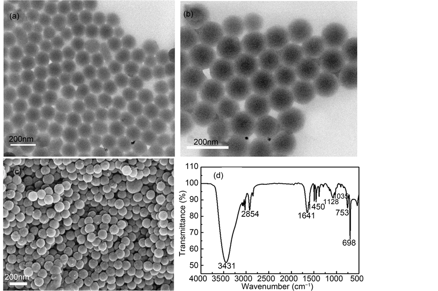
Figure 3. (a)-(b) TEM images, (c) SEM images and (d) FTIR spectra of SHSS samples.
orange red FeOOH phase [20] . The completely coprecipitation of Fe3+ with Fe2+ ions generally occurs at above pH 9.2, which can be written in the following:

On the other hand, deposition speed of Fe3+ ions are faster than that of Fe2+ ions, due to their different  between Fe3+ ion and Fe2+. The
 , Fe(OH)3 = 3.98 × 10−38, and
 , Fe(OH)2 = 7.94 × 10⁻¹⁶, so the precipitate of Fe3+ and Fe2+ occur at pH 3 - 4 and pH 8 - 9 based on the calculations from their
  respectively. When coprecipitation of Fe3+ with Fe2+ ions occurs at 2:1 ratio of [Fe2+] to [Fe3+], the precipitate of Fe3+ preferentially occurs, then co-precipitation of Fe2+ with Fe3+ promoted the Fe3O4 crystal deposition on SHSS surface. But when the mole ratio of [Fe2+] to [Fe3+] is 2:2, shortfall amount of Fe2+ ions are not enough to support whole Fe3+ ions approaches to Fe3O4 crystal deposition, due to Fe2+ liable to be oxidized by trace amount oxygen in the air. Thus, the excess Fe3+ ions can accelerate the electrostatic adsorption between new-formed Fe3O4 crystals, resulting in formation of MHSS-b with severe aggregation on SHSS surface, as shown in Figure 4(b).
Whether an absence of Fe3+ ions is favorable to Fe3O4 crystal deposition on SHSS surface, there is unsatisfied answer shown in Figure 4(c). It is because at 2:0 ratio of [Fe2+] to [Fe3+], the Fe3+ ions employed for Fe3O4 crystal deposition can only be obtained by oxidization of Fe2+ with trace hydrogen peroxide residued in synthesis process. Therefore few obtained Fe3+ ions can be applied to participate Fe3O4 crystal deposition on SHSS surface, which leads to generation of MHSS-c with the small amount of magnetic particles covered on SHSS surface (Figure 4(a)) [21] .
Second, the influence of the total iron concentration must be considered, when the mole ratio of [Fe2+] to [Fe3+] is controlled at 2:1, and the total iron concentration is 0.05 M, the image of MHSS-d recorded in Figure 4(d) still shows hollow silica/magnetic composite spheres, it can be seen Fe3O4 layer of 2 - 3 nm thickness are coated on SHSS surface, which is much thinner than the Fe3O4 coating layer prepared at the total iron concentration of 0.10 M. It demonstrates that total iron concentration can influence the thickness of Fe3O4 coating layer on the SHSS surface, appropriate iron concentration can improve Fe3O4 crystal deposition on the SHSS surface, less iron concentration can only form thin Fe3O4 coating layer.
To further confirm the crystalline structure, XRD measurement was used to analyze the sample of varying the concentration of iron salts and different ratio of [Fe2+]/[Fe3+]. The diffraction peaks of the particles synthesized in this study were measured to be 2θ = 29.70, 35.06, 42.71, 56.60, 62.20, corresponding to (2 2 0), (3 1 1), (4 0 0), (5 1 1) and (4 4 0) crystal planes of the Fe3O4 respectively (Figure 5). It can be found that well-resolved diffraction peaks appeared on the pattern, and the pattern can be indexed to Fe3O4 (JCPDS#79-0418) according to the reflection peak positions and relative intensities, which confirms the magnetite structure of this sample. The consistence of four curves in Figure 5 demonstrated that there was no crystal transition of the magnetic nanoparticles when the iron salts concentrations and the molar ratio of [Fe2+]/[Fe3+] change.
The results of indexing to the powder X-ray diffraction pattern of Figure 5 are listed in Table 2. It can be inferred from Table 2 that all MHSS samples have monoclinic
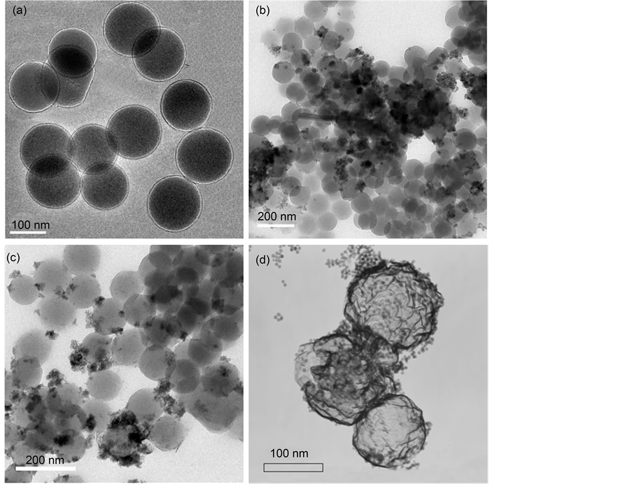
Figure 4. TEM of magnetite nanoparticles prepared at various iron salts concentrations and the molar ratio of [Fe2+]/[Fe3+]: (a) 0.10 M, 2:1, MHSS-a; (b) 0.05 M, 2:2, MHSS-b; (c) 0.05 M, 2:0, MHSS-c; and (d) 0.05 M, 2:1, MHSS-d.
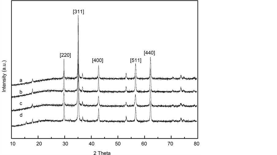
Figure 5. XRD patterns of magnetite nanoparticles prepared at various iron salts concentrations and the molar ratio of [Fe2+]/ [Fe3+]: (a) MHSS-a; (b) MHSS-b; (c) MHSS-c; and (d) MHSS-d.
Table 2. The experimental data and the calculated results for powder X-ray diffraction pattern of MHSS by varying iron salts concentrations and the molar ratio of [Fe2+]/[Fe3+].
Note: D is calculated value, Do is original value.
symmetry, the lattice parameters of MHSS-a, MHSS-b, MHSS-c and MHSS-d samples were (a = 2.2597, b = 1.8097, c = 2.6941, β = 100.512˚), (a = 2.2682, b = 1.8068, c = 2.6965, β = 100.25˚), (a = 2.2725 nm, b = 1.808 nm, c = 2.6788 nm, β = 100.242˚) and (a = 2.2680 nm, b = 1.8102 nm, c = 2.6.949 nm, β = 100.44˚) respectively, the minimum relative deviation between the calculated D and original Do is 0.0008‰ for MHSS-a. The MHSS-a has a largest cell angle (β) of unit cell at 100.512˚, the MHSS-d has a second large cell angle (β), and the MHSS-c has a minimum cell angle (β). Because there is intimate relationship between spherical shell’s surface curvature and the cell angle of unit cell [22] , as shown in the model structure (Figure 6), the unit cell dimensions a, b and c(001) and cell angle β will vary from unit cell to unit cell along the surface curvature of the spherical shell. Thus the larger angle the unit cell shows, the more spherical shell curvature, and the sample has a well-defined spherical shell. In comparison with Figure 4, the image of MHSS-a recorded in Figure 4(a) has an obvious spherical structure, the image of MHSS-d has approximate spherical structure, indicating the findings are related to their cell angles (β) of unit cell.
The Fe3O4 content of the spheres surface can be controlled by changing the amount of the ratio of [Fe2+]/[Fe3+] or the concentration of iron salts. Magnetic testing results of MHSS were shown in Figure 7 and Table 3. The magnetization saturation (Ms) of MHSS spheres are shown in Table 3, it can be seen from the results that MHSS-ahasthe highest saturation magnetization at 34.38 emu/g, MHSS-b has the second at 24.38 emu/g, MHSS-d has the third at 18.77 emu/g, but MHSS-c has the minimum value at 11.80 emu/g. The coercivity are close to zero, indicating they all belong to super- paramagnetic system. It can be seen that the Ms value of the MHSS increases with the concentration ofsalt solution increasing, due to a difference of the magnetic layer thickness. And Ms value of the MHSS increases with an increase of Fe3+ content in the ratio of [Fe2+]/[Fe3+], due to appropriate Fe3+ amount being able to improve deposition of Fe3O4. Considering MHSS-a having the highest saturation magnetization at 34.38 emu/g, MHSS-a could be selected as carrier of targeted drugsin this paper, providing the empirical research basisfor highly efficient antitumor with low toxicity.
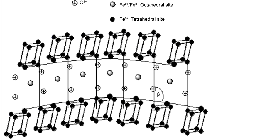
Figure 6. Change in unit cell angle β for a curved crystal.  = unit cell of Fe3O4 with monoclinic symmetry.
  small black circles = lattice site of Monoclinic crystal cell located Tetrahedral site;
  large black circles = lattice site of Monoclinic crystal cell linked to negative oxygen ion located in Octahedral site;
  gray circles = Fe2+/Fe3+ located in octahedral site.
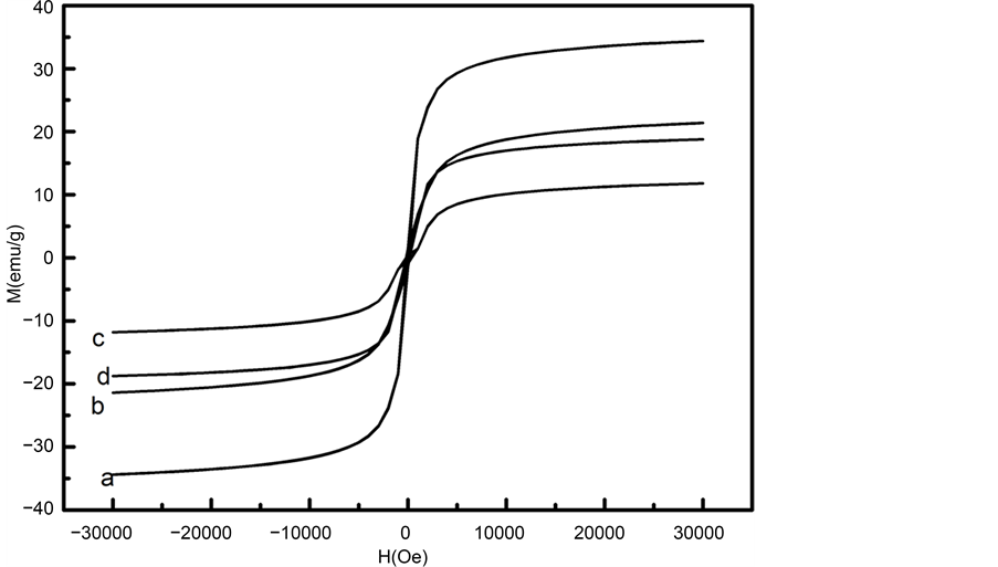
Figure 7. Magnetization curves of magnetite nanoparticles prepared at various iron salts concentrations and the molar ratio of [Fe2+]/[Fe3+]: (a) MHSS-a;, (b) MHSS-b; (c) MHSS-c; and (d) MHSS-d.
Table 3. The magnetic parameters of MHSS at different the molar ratio of [Fe2+]/[Fe3+].
3.4. In Vivo Biodistribution Studies and SPECT Imaging
For the radiolabeling of MHSS, the unlabelled amino-functionalized-MHSS were mixed with radioactive Na99Tcm O4 in the presence of SnCl2, which could reduce 99Tcm (VII) into 99Tcm(III) ions. [23] , it was found that 99Tcm3+ ions could also be anchored on the inner cavity of MHSS by coordinating bond between low valent 99Tcm3+ ions and -NH2 groups (Figure 8). The obtained labelled MHSS compound was washed with physiological saline, and following seperated by strong magnet for three times to remove excess free 99Tcm. The radiochemical purity of the labeled compound was checked with Capintec CRC-15R external dose calibrator. The purified MHSS-NH2-99mTc was dispersed in physiological saline to generate 20 mg/2.5 mL of labeled compound solution by supersonic treatment. The labeling yield of 99mTc was then determined to be 81%. To determine the radiostability, MHSS-NH2-99mTc were incubated in mouse serum for 40 h. Nanoparticles remained stable with>96% of the nanoparticles remaining 99mTc- bound after 24 h. At the final time point (72 h), 90.2 ± 1.7% of nanoparticles were found to be stable, thus confirming the enhanced stability of MHSS-NH2-99mTc in mouse serum (Figure 9).
99Tcm labelled MHSS particles not only enabled enhanced internal radioisotope therapy [24] , but also allowed us to quantitatively track the in vivo behaviors of those nanoparticle after they were administered into animals. The female normal mouse was intravenously injected with MHSS-NH2-99mTc and then scanned under single photoemission-computed tomography (SPECT) imaging. Due to the wide distribution of each labelled MHSS particles throughout the body after injection of MHSS-NH2-99mTc, high levels of radioactivity accumulation were observed in the liver, spleen, kidneys, and bladder after 2 h post injection, but a small amount of radioactive particles uptake in the lungs (Figure 10(a)). The results show the labelled MHSS particles can successfully break through the pulmonary circulation, and excreted through the urinary system. Instead the MHSS-NH2-99mTc particles were swallowed by reticuloendothelial system (lung, liver and spleen).
In order to explore the targeting properties of labelled MHSS particles, the VX2 tumor mice, a fast-growing tumor model were each injected 0.5 mCi/1 ml of MHSS-NH2-99mTc via tail vein, and the tumor of nudemice was placed on the magnetic pole of the YMC-11 medical pulse magnetic field generator with the output voltage of pulsed magnetic fields being controlled at 700 V for 2 h. In Figure 10(b), the right forelimb (A) is normal, the left forelimb (B) is the tumor region with targeting, the left hind limb (C) is the tumor region with no targeting and the right hind limb (D) is a sense of inflammation.
Figure 10(b) shows nude mice SPECT imaging targeting to forelimb after injection, the intensive distribution of black dots in the image correspond to the large amount of 99Tcm labelled MHSS particles were accumulated into the tumor sites by a combination of passive magnetic targeting and active targeting mechanisms. So in comparison to the in vivo bio-distribution of 99Tcm labelled MHSS particles, the targeting SPECT imaging show the activity concentration of labelled MHSS particles in tumour were significantly higher than that without targeting.
Table 4 shows the results of magnetically targeted radiotherapy employed 99Tcm labelled MHSS, the liver uptake of 99Tcm labelled MHSS was 16.4979, 14.3941, 13.4595, 13.4550 and 14.2896 % ID/g at 15, 30, 60, 120 and 180 min respectively, the radioactivity in the spleen was 13.9908, 14.3385, 12.0734, 12.9458 and 13.8828 % ID/g at 15, 30, 60, 120 and180 min, respectively, the results show MHSS-a has the highest liver uptake of 99Tcm for 180 min after the injection, when the absolute organ uptake is compared, uptake by the spleen is the second highest, and uptake by the lung is the third highest, the findings are in a good agreement with SPECT imaging data with high levels of
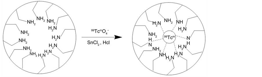
Figure 8. The illustration for the Technetium-99 label.
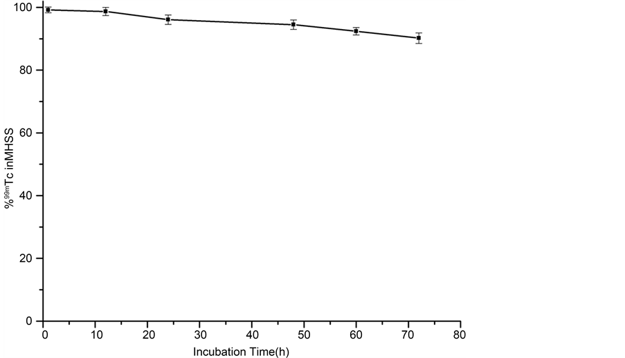
Figure 9. MHSS-NH2-99mTc stability was examined by incubation in mouse serum.
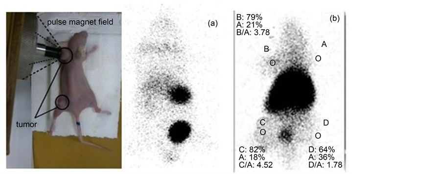
Figure 10. The SPECT images of the mice after injection with MHSS-99Tcm nanoparticles by a) no targeting and b) targeting for 2 h.
Table 4. Biodistribution of MHSS-99Tcm nanoparticles in mice (three mice per time point) (%ID/g).
99Tcm labelled MHSS uptake in the liver, spleen and lung. On the contrary, low radioactivity uptake was observed in pancreas, brain and bone, probably because 99Tcm labelled MHSS is rapidly cleared by pancreas, brain and bone, and excreted by mouse into the urine.
4. Conclusion
In this paper, an efficient functionalized SiO2 sphere templating route has been developed to prepare magnetic hollow silica spheres (MHSS) with uniform 70 nm cavity diameter size and 15 nm shell thickness respectively. The unit cell parameters of them have been calculated according to the results of indexing to the XRD pattern, they all belong to monoclinic symmetry. The MHSS-a has a largest cell angle (β) of unit cell, so having a perfect spherical morphology with the highest saturation magnetization at 34.38 emu/g. The magnetic properties and morphologies of MHSS were affected by the [Fe2+]/[Fe3+] molar ratio and the iron salts concentration. As in vivo application, the 99Tcm labelled MHSS were injected into the mice to study the biodistribution of magnetic nanoparticles in different organs, and the results revealed that MHSS were found to accumulate in the spleen, lung and liver, showing obvious magnetic targeting effects in the mouse. The findings demonstrate that magnetic hollow silica spheres have great potential in the magnetic targeted drug delivery system.
Acknowledgements
This work was supported by the National Natural Science Foundation of China (20577010, 20971043) and the Fundamental Research Funds from the Central Universities.
Cite this paper
Liu, Y.C., Li, X.Z., Sloppy, J., Huang, Y., Yao, P.P., Yang, J.Y. and Yang, Y.X. (2017) A Simple and “Green” Method for Synthesis of Magnetic Hollow Silica Spheres and Its 99Tcm Labeled Targeting Studies. Open Journal of Inorganic Chemistry, 7, 1-15. http://dx.doi.org/10.4236/ojic.2017.710001
References
- 1. Teng, F., Xu, T., Liang, S., Buergen, G., Yao, W. and Zhu, Y. (2008) Synthesis of Hollow Mn3O4-in-Co3O4 Magnetic Microspheres and Its Chemiluminescence and Catalytic Properties. Catalysis Communications, 9, 1119-1124.
https://doi.org/10.1016/j.catcom.2007.10.032 - 2. Sadasivan, S. and Sukhorukov, G.B. (2006) Fabrication of Hollow Multifunctional Spheres Containing MCM-41 Nanoparticles and Magnetite Nanoparticles Using Layer-by-Layer Method. Journal of Colloid and Interface Science, 304, 437-441.
https://doi.org/10.1016/j.jcis.2006.09.010 - 3. Gruner, M.E. and Entel, P. (2007) Magnetic Properties of Nanostructured Hollow Microspheres. Journal of Magnetism and Magnetic Materials, 310, 2453-2455.
https://doi.org/10.1016/j.jmmm.2006.10.917 - 4. Wu, W., DeCoster, M.A., Daniel, B.M., Chen, J.F., Yu, M.H., Cruntu, D. and Zhou, W.L. (2006) One-Step Synthesis of Magnetic Hollow Silica and Their Application for Nanomedicine. Journal of Applied Physics, 99, 08H104.
- 5. Zhou, J., Wu, W., Caruntu, D., Yu, M.H., Martin, A., Chen, J.F. and Zhou, W.L. (2007) Synthesis of Porous Magnetic Hollow Silica Nanospheres for Nanomedicine Application. The Journal of Physical Chemistry C, 111, 17473-17477.
https://doi.org/10.1021/jp074123i - 6. Zhou, W., Gao, P., Shao, L., Caruntu, D., Yu, M., Chen, J. and O’Connor, C.J. (2005) Drug-Loaded, Magnetic, Hollow Silica Nanocomposites for Nanomedicine. Nanomedicine: Nanotechnology, Biology and Medicine, 1, 233-237.
https://doi.org/10.1016/j.nano.2005.06.005 - 7. Fuertes, A.B., Valdés-Solís, T., Sevilla, M. and Tartaj, P. (2008) Fabrication of Monodisperse Mesoporous Carbon Capsules Decorated with Ferrite Nanoparticles. The Journal of Physical Chemistry C, 112, 3648-3654.
https://doi.org/10.1021/jp711248h - 8. Shao, L., Caruntu, D., Chen, J.F., O’Connor, C.J. and Zhou, W.L. (2005) Fabrication of Magnetic Hollow Silica Nanospheres for Bioapplications. Journal of Applied Physics, 97, Article ID: 10Q908.
https://doi.org/10.1063/1.1851885 - 9. Pu, H.T., Jiang, F.J. and Yang, Z.L. (2006) Preparation and Properties of Soft Magnetic Particles Based on Fe3O4 and Hollow Polystyrene Microsphere Composite. Materials Chemistry and Physics, 100, 10-14.
https://doi.org/10.1016/j.matchemphys.2005.11.032 - 10. Caruso, F., Spasova, M., Susha, A., Giersig, M. and Caruso, R.A. (2001) Magnetic Nanocomposite Particles and Hollow Spheres Constructed by a Sequential Layering Approach. Chemistry of Materials, 13, 109-116.
https://doi.org/10.1021/cm001164h - 11. Tartaj, P., Gonzalez-Carreno, T. and Serna, C.J. (2001) Single-Step Nanoengineering of Silica Coated Maghemite Hollow Spheres with Tunable Magnetic Properties. Advanced Materials, 13, 1620-1624.
https://doi.org/10.1002/1521-4095(200111)13:21<1620::AID-ADMA1620>3.0.CO;2-Z - 12. Wu, W., Caruntu, D., Martin, A., Yu, M.H., O’Connor, C.J., Zhou, W.L. and Chen, J.F. (2007) Synthesis of Magnetic Hollow Silica Using Polystyrene Bead as a Template. Journal of Magnetism and Magnetic Materials, 311, 578-582.
https://doi.org/10.1016/j.jmmm.2006.08.016 - 13. Zhu, Y., Ikoma, T., Hanagata, N. and Kaskel, S. (2010) Rattle-Type Fe3O4@SiO2 Hollow Mesoporous Spheres as Carriers for Drug Delivery. Small, 6, 471-478.
https://doi.org/10.1002/smll.200901403 - 14. Caruso, F., Spasova, M., Susha, A., Giersig, M. and Caruso, R.A. (2001) Magnetic Nanocomposite Particles and Hollow Spheres Constructed by a Sequential Layering Approach. Chemistry of Materials, 13, 109-116.
https://doi.org/10.1021/cm001164h - 15. Zhao, W., Chen, H., Li, Y., Li, L., Lang, M. and Shi, J. (2008) Uniform Rattle-Type Hollow Magnetic Mesoporous Spheres as Drug Delivery Carriers and Their Sustained-Release Property. Advanced Functional Materials, 18, 2780-2788.
https://doi.org/10.1002/adfm.200701317 - 16. Radziuk, D., Shchukin, D.G., Skirtach, A., Mohwald, H. and Sukhorukov, G. (2007) Synthesis of Silver Nanoparticles for Remote Opening of Polyelectrolyte Microcapsules. Langmuir, 23, 4612-4617.
https://doi.org/10.1021/la063420w - 17. Reetz, M.T. and Jaeger, K.E. (2000) Enantioselective Enzymes for Organic Synthesis Created by Directed Evolution. Chemistry—A European Journal, 6, 407-412.
https://doi.org/10.1002/(SICI)1521-3765(20000204)6:3<407::AID-CHEM407>3.0.CO;2-Y - 18. Deng, Z., Chen, M., Gu, G. and Wu, L. (2008) A Facile Method to Fabricate ZnO Hollow Spheres and Their Photocatalytic Property. The Journal of Physical Chemistry B, 112, 16-22.
https://doi.org/10.1021/jp077662w - 19. Chen, M., Wu, L., Zhou, S. and You, B. (2006) A Method for The Fabrication of Monodisperse Hollow Silica Spheres. Advanced Materials, 18, 801-806.
https://doi.org/10.1002/adma.200501528 - 20. Liang, X., Shi, H., Jia, X., Yang, Y. and Liu, X. (2011) Dispersibility, Shape and Magnetic Properties of Nano-Fe3O4 Particles. Materials Sciences and Applications, 2, 1644.
https://doi.org/10.4236/msa.2011.211219 - 21. Yuan, J., Zhang, X. and Qian, H. (2010) A Novel Approach to Fabrication of Superparamagnetite Hollow Silica/Magnetic Composite Spheres. Journal of Magnetism and Magnetic Materials, 322, 2172-2176.
https://doi.org/10.1016/j.jmmm.2010.02.004 - 22. Eggleton, R.A. and Tilley, D.B. (1998) Hisingerite: A Ferric Kaolin Mineral with Curved Morphology. Clays and Clay Minerals, 46, 400-413.
https://doi.org/10.1346/CCMN.1998.0460404 - 23. Dong, C., Zhao, H., Yang, S., Shi, J., Huang, J., Cui, L. and Jia, B. (2013) 99mTc-Labeled Dimeric Octreotide Peptide: A Radiotracer with High Tumor Uptake for Single-Photon Emission Computed Tomography Imaging of Somatostatin Receptor Subtype 2-Positive Tumors. Molecular Pharmaceutics, 10, 2925-2933.
https://doi.org/10.1021/mp400040z - 24. Liu, Z., Huang, J., Dong, C., Cui, L., Jin, X., Jia, B. and Wang, F. (2012) 99mTc-Labeled RGD-BBN Peptide for Small-Animal SPECT/CT of Lung Carcinoma. Molecular Pharmaceutics, 9, 1409-1417.
https://doi.org/10.1021/mp200661t