Open Journal of Antennas and Propagation
Vol.06 No.01(2018), Article ID:83497,14 pages
10.4236/ojapr.2018.61001
Design of a Multiband Patch Antenna for 5G Communication Systems
Atik Mahabub1, Md. Mostafizur Rahman1, Md. Al-Amin2, Md. Sayedur Rahman1, Md. Masud Rana1*
1Department of Electronics and Communication Engineering, KUET, Khulna, Bangladesh
2Department of Electrical and Electronic Engineering, KUET, Khulna, Bangladesh
![]()
Copyright © 2018 by authors and Scientific Research Publishing Inc.
This work is licensed under the Creative Commons Attribution International License (CC BY 4.0).
http://creativecommons.org/licenses/by/4.0/


Received: February 4, 2018; Accepted: March 27, 2018; Published: March 30, 2018
ABSTRACT
Currently, communication system requires multiband small antennas for 5G mobile applications. Driven this motivation, this paper proposes a multiband patch antenna for Wi-Fi, WiMAX and 5G applications. The proposed antenna can effectively operate at 2.4 GHz as Wi-Fi, 7.8 GHz as WiMAX and 33.5 GHz as 5G communication purposes. The proposed antenna arrays have given directional radiation patterns, very small voltage standing wave ratio, high gain (VSWR) and directivity for each aforementioned systems operating frequency. This antenna is made for multiband purpose which can be effective for not only Wi-Fi and WiMAX but also 5G applications.
Keywords:
5G Communication Systems, Multiband, Patch Antenna, Wi-Fi and WiMAX Systems

1. Introduction
Wi-Fi improves the third-generation (3G) cellular and long-term evolution (LTE) broadband internet access. The IEEE 802.11 a/b/g/n standards have support for frequency, polarization, and spatial diversity to meet the demand for higher throughput with greater coverage. Wi-Fi systems frequency ranges from 2.4 to 2.485 GHz as well as 5.150 - 5.350 GHz, 5.470 - 5.725 GHz, and 5.725 - 5.850 GHz. The channel bandwidth within each band varies from 5 to 20 MHz [1] [2] . A compact Size dual band WIFI antenna simulation using existing components in smartphone can provide efficiency of 54.8% and gain is 2.0 dBi at 2.45 GHz [3] . A circularly polarized switched beam antenna with pattern diversity for Wi-Fi applications covers an angular range of 180 degrees with 7 dB of ripple and with the maximum gain of 2.8 dB [4] . This proposed antenna also can be worked for Wi-Fi system which gives more bandwidth about 150 MHz, directivity gain is about 6 dBi from the above literature papers. For improving WiMAX frequency and bandwidth in recent years, several printed monopole antennas [5] [6] and slot antennas [7] [8] have been proposed for Wi-Fi/WiMAX applications. However, most of them have large dimensions and do not pay attention to interference suppression [9] . In this paper, WiMAX and Wi-Fi both are proposed which works on small dimensions about 3.5 × 3.6 × 1 mm3 and special attention is paid for interference suppression which makes this antenna more effective from the above literature works.
Conventional 4G technology uses frequency band of 2 - 8 GHz providing a bandwidth of 5 - 20 MHz but, nowadays as IoT is becoming popular, user bandwidth requirement has increased. To support this large data traffic 5G is the latest possible solution. For 5G, frequencies of around 50 GHz are being considered and this will present some real challenges in terms of the circuit design. 5G antennas are expected to be smaller, high-gain systems than those that have served 3G and 4G systems, and they will need more advanced steering and scanning techniques in order to function well at millimeter wave frequencies. Using frequencies much higher in the frequency spectrum provides the possibility of having wider channel bandwidth possibly 1 - 2 GHz. However, this poses new challenges for handset development where maximum frequencies of around 2 GHz and bandwidths of 10 - 20 MHz are currently in use. Recent works shows to show that a four-element dual-band printed slot antenna array for 5G mobile communication networks provide good impedance matching at the desired frequency bands of 28/38 GHz for |S11| less than −10 dB, with a gain of 10.58 dBi at 28 GHz and 12.15 dBi at 38 GHz [10] . An antenna with high gain and beam steerable can be designed for 5G cellular handset devices. Some recent works on high gain and beam steering have been published in last few years [11] [12] [13] . A compact T-shaped slotted micro strip patch antenna can provide reflection coefficient below −10 dB from 55.80 GHz to 67 GHz. The gain of antenna is 6.34 dB [14] . This proposed 5G antenna, 5G system works at 33.5 GHz gain is about 9 dBi which is more and less return loss about −29 dB is referred from above literature works. For its operating frequency is on 33.5 GHz which makes this antenna more economical for the mobile operators to establish 5G system.
This paper introduces an advanced multiband patch antenna to explore the possibility of covering frequency bands of Wi-Fi, WiMAX and 5G. At the first time a triple band 5G antenna has been proposed in this paper. This antenna is more compact, highly directive which is essential for mobile application. It also has a very small return loss compared with other existing antennas. Its enormous bandwidth makes this antenna more appropriate for wireless communication systems.
2. Antenna Design
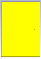
The geometric and detailed information of the proposed advanced patch antenna is shown in Figure 1 whose ground has been made with copper (lossy) and substrate with FR-4 (lossy) with relative permittivity constant of 4.4 and the thickness of 0.8 mm. The overall dimensions of 62 × 50 × 1 mm3 are suitable for the smartphone or mobile applications and no over height is necessary in utilizing the proposed antenna for the mobile handset [15] . The antenna is designed and simulated using CST Microwave Studio 2015 software.
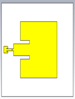
The large patch element comparing between the twos is made for the keeping in mind of the measurement of 2.4 GHz which is for Wi-Fi application. The smaller patch element comparing between the twos is made for the keeping in mind of the measurement of 33.5 GHz which is for 5G application. Both the patch elements are connected through co-axial feed cable which has been passed through the ground for the input or output connection. Actually 31.6 × 30 mm2 is covered by the larger patch for the Wi-Fi application and 3.5 × 3.6 mm2 is covered by the smaller patch for 5G application. The WiMAX is possible because of the extended feeding line of the both of the patches for this reason it works in between of the applications at 7.8 GHz. The designed antenna is shown in Figure 2, which represents the simulated design configuration.

Figure 1. Geometric and detailed information of the proposed antenna (a) front view; (b) side view.
 (a)
(a)
 (b)
(b)
 (c)
(c)
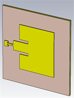
Figure 2. Simulated view of the antenna from CST (a) full view 3D; (b) top view; (c) back view.
3. Results and Analysis
3.1. S-Parameter
From the simulation of the antenna, it has been observed that the S-parameter at the range of 1 GHz to 38 GHz. The entire result of S-parameter has been shown in Figure 3.
Figure 3 shows the simulated results of response of the proposed antenna. It can be observed from the simulated result is that this antenna is a multiband antenna and operated at 2.4 GHz, 7.8 GHz and 33.5 GHz. Though there are five other operated bands at the range of 9 - 15 GHz which is below −10 dB, they cannot fulfil the requirement of any communication systems.
In Figure 4, it can be seen that the operating frequency is 2.4 GHz which is the frequency band allocated for Wi-Fi application for IEEE standard 802.11. From this figure, it can be observed that the return loss is about −22.37 dB which is much below from the −10 dB and the bandwidth is about 150 MHz which can be used for wideband Wi-Fi applications. Usually, the bandwidth is needed of 20 - 40 MHz for the Wi-Fi application which is discussed in Table 1. For this reason, multiple channels can be used by this antenna.
In Figure 5, it can be seen from that the operating frequency is 7.8 GHz which is the frequency band allocated for WiMAX application for IEEE standard 802.16a. From the Figure 5, it can be observed that the return loss is about −26 dB which is −14 dB less than the −10 dB and the bandwidth is about 235 MHz at −10 dB range which can be used for wideband WiMAX application and discussed in Table 1. This antenna offers efficient bandwidth for WiMAX purpose and the low return loss represents antenna will work effectively at 7.8 GHz operating frequency for WiMAX.
In Figure 6, it can be seen from that the operating frequency is 33.5 GHz which is the frequency band allocated for 5G application. Basically, 5G mobile application works above 20 GHz frequency and having a bandwidth above 1 GHz [16] . But in this case, the bandwidth is above the 1 GHz and it is approximately 4.5 GHz which can cover more channels having larger bandwidths.

Figure 3. S-Parameter of the future advanced multiband patch antenna.
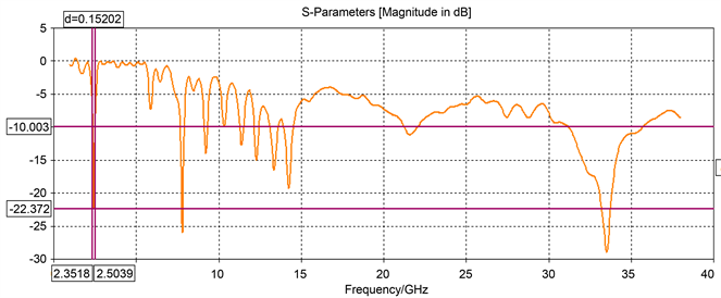
Figure 4. Return loss & bandwidth measurement from the S-Parameter for Wi-Fi application.
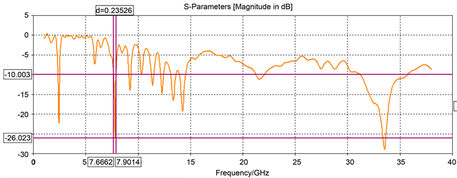
Figure 5. Return loss & bandwidth measurement from the S-Parameter for WiMAX applications.
![]()
Figure 6. Return loss & bandwidth measurement from the S-Parameter for 5G application.

Table 1. Data from the S-parameter for Wi-Fi, WiMAX and 5G applications.
From the simulated result, it has been shown that the least return loss of the proposed antenna occurred at 33.5 GHz and it is about −29 dB and the bandwidth of this application is about 4.5 GHz which is discussed in Table 1 and meets the requirements.
From the Table 1, it can be observed that this proposed future multi-band antenna fulfils the requirements of Wi-Fi, WiMAX and 5G applications which has been shown from the S-parameter.
3.2. Voltage Standing Wave Ratio (VSWR)
The value of VSWR should be between 1 and 2 for efficient performance of an antenna [17] . Figure 7 shows the simulated result of VSWR plot on the basis of frequency. From Figure 7, it can be observed that the value of VSWR is less than 1.3 at the operating frequency of Wi-Fi, WiMAX and 5G applications. Figure 7(a) shows that VSWR at 2.4 GHz is about 1.27 which for Wi-Fi, Figure 7(b) shows that VSWR at 7.8 GHz is about 1.11 which is for WiMAX and Figure 7(c) shows that least for the 5G about 1.07 at 33.5 GHz. All of them are discussed in Table 2.
3.3. Efficiency
The total efficiency of an antenna is the radiated efficiency multiplied by impedance mismatch loss of the antenna, when connected to a transmission line or receiver. If is the total efficiency, is the impedance mismatch loss or
![]()
Figure 7. VSWR for (a) Wi-Fi; (b) WiMAX; and (c) 5G communication systems.
antenna’s loss and is the radiated efficiency then,
Table 2. Simulated results of VSWR for Wi-Fi, WiMAX and 5G communication systems for proposed antenna.
This equation [18] referred the relationship total efficiency with radiated efficiency. is from 1 to 0 in value.
In this proposed antenna, for Wi-Fi, WiMAX and 5G operating frequency, the lower antenna loss or impedance mismatch has been occurred from Figure 8. At 2.4 GHz, for Wi-Fi application, the radiated efficiency is −9.15 and total efficiency is −9.20 and the difference is about 0.05 and antenna efficiency is about 99.5%. At 7.8 GHz, for WiMAX application, the radiated efficiency is −5.56 and total efficiency is −5.57 and the difference is about 0.01 and antenna efficiency is 99.8%. At 33.5 GHz, for 5G application, the radiated efficiency is −3.33 and total efficiency is −3.34 and the difference is about 0.01 and antenna efficiency is 99.7%. All the values of Radiated and total efficiency are measured in dB and discussed in Table 3.
3.4. Radiation Efficiency with Respect to Radiated and Accepted Power
The radiation efficiency is the ratio of radiated power to the accepted power or input power of an antenna. If radiation efficiency is η, accepted power is and radiated power is . then,
(1)
Figure 9 shows the accepted and radiated power for the proposed antenna. From the analysis of Figure 9, at 2.4 GHz, 7.8 GHz and 33.5 GHz the accepted power and the radiated power is high. For that reason, radiation efficiency is also high on that frequency range. At 2.4 GHz, for Wi-Fi, the accepted power is about −3 dB and received power is about −12.2 dB. From the Equation (1), the radiated efficiency is about 24.6% at 2.4 GHz for Wi-Fi. At 7.8 GHz, for WiMAX, the accepted power is about −3 dB and received power is about −8.3 dB. From the Equation (1), the radiated efficiency is about 35.8% at 7.8 GHz for WiMAX. At 33.5 GHz, for 5G application, the accepted power is about −3 dB and received power is about −7.2 dB. From the Equation (1), the radiated efficiency is about 41.67% at 33.5 GHz for 5G. These data are discussed in Table 4.
3.5. Radiation Pattern
3.5.1. 5G
At 33 GHz, for 5G application, from the analysis of far-field in Figure 10, it is highly directive antenna and directivity is 8.4 dBi. Main lobe direction is 5.0 degree, angular bandwidth at 3 dB point is 62 degree and side lobe level is −3.4 dB.
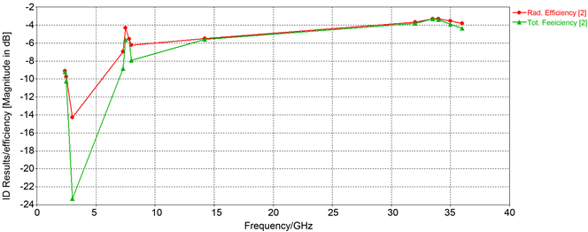
Figure 8. Comparison between radiated efficiency and total efficiency for proposed antenna with respect to frequency.
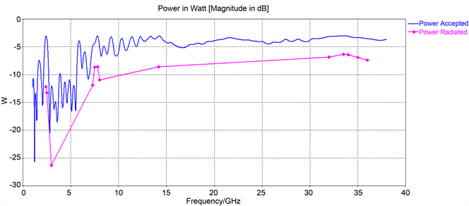
Figure 9. Radiated and accepted power of the proposed antenna for different communication systems with respect to frequency.
The e-field for main lobe magnitude is 19.8 dBV/m, h-field for main lobe magnitude is −31.7 dBA/m and power of the pattern is −5.93 dBW/m2. The gain of the radiation pattern is 5.06 for main lobe magnitude. All of them are discussed in Table 5.
3.5.2. WiMAX
At 7.8 GHz, for WiMAX application, from the analysis of far-field in Figure 11, it is highly directive antenna and directivity is 6.62 dBi. Main lobe direction is 35.0 degree, angular bandwidth at 3 dB point is 49 degree and side lobe level is −14.1 dB. The e-field for main lobe magnitude is 15.8 dBV/m, h-field for main lobe magnitude is −35.7 dBA/m and power of the pattern is −9.96 dBW/m2. The gain of the radiation pattern is 1.1 for main lobe magnitude. All of them are discussed in Table 5.

Figure 10. Radiation pattern analysis for 5G application (a) far-field directivity 3d; (b) far-field directivity (polar form); (c) gain; (d) e-field; (e) h-field; (f) Power pattern.
Table 3. Radiated efficiency and total efficiency for different communication systems for this proposed antenna.
Table 4. Radiated efficiency with respect accepted power and radiated power for different communication systems for the proposed antenna.
3.5.3. Wi-Fi
At 2.4 GHz, for Wi-Fi application, from the analysis of far-field in Figure 12, it is highly directive antenna and directivity is 5.9 dBi. Main lobe direction is 0.0
Table 5. Directivity, gain, e-field, h-field, power pattern, angular bandwidth for 5G, WiMAX, Wi-Fi applications from the analysis of radiation pattern.
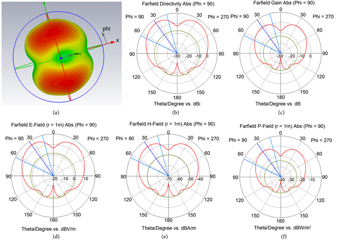
Figure 11. Radiation pattern analysis for WiMAX application (a) far-field directivity 3d; (b) far-field directivity (polar form); (c) gain; (d) e-field; (e) h-field; (f) Power pattern.
degree, angular bandwidth at 3 dB point is 101.8 degree and side lobe level is none. The e-field for main lobe magnitude is 11.5 dBV/m, h-field for main lobe magnitude is −40.1 dBA/m and power of the pattern is −14.3 dBW/m2. The gain of the radiation pattern is −3.3 dB for main lobe magnitude. All of them are discussed in Table 5.
4. Conclusions and Future Works
An advanced multiband simply structured patch antenna has been designed and simulated by the help of CST Microwave Studio software. This antenna can be potential for future mobile communication systems as it can operate not only at

Figure 12. Radiation pattern analysis for Wi-Fi application (a) far-field directivity 3d; (b) far-field directivity (polar form); (c) gain; (d) e-field; (e) h-field; (f) Power pattern.
Wi-Fi & WiMAX bands but also 5G frequency band. This antenna satisfies the basic needs of Wi-Fi, WiMAX and 5G operations having the bandwidth of 152 MHz, 235 MHz and 4.5 GHz respectively. Because of its low VSWR and high directivity this antenna can be very effective for the next generations’ communication purposes.
Though this antenna has various advantages, it can be improved. In future, this antenna’s height and width can be deduced to make it light-weight, more frequency bands can be added to it to make it more effective and directivity can be improved so that it can cover more areas.
Acknowledgements
The authors would like to thank the anonymous reviewers. Authors also thank to the Department of Electronics and Communication Engineering, Khulna University of Engineering & Technology to support. Note that the first author conducted simulations and first, third and fourth authors wrote the whole paper, whereas the other two authors supervised the first author. The fifth author is provided paper writing guideline and technical corrections.
Cite this paper
Mahabub, A., Rahman, Md.M., Al-Amin, Md., Rahman, Md.S. and Rana, Md.M. (2018) Design of a Multiband Patch Antenna for 5G Communication Systems. Open Journal of Antennas and Propagation, 6, 1-14. https://doi.org/10.4236/ojapr.2018.61001
References
- 1. Chen, Z.N., Qing, X., See, T.S.P. and Toh, W.K. (2012) Antennas for WiFi Connectivity. Proceedings of the IEEE, 100, 2322-2329. https://doi.org/10.1109/JPROC.2012.2183830
- 2. Mahabub, A., Islam, Md.N. and Rahman, Md.M. (2017) An Advanced Design of Pattern Reconfigurable Antenna for Wi-Fi and WiMAX Base Station. Proceeding of the 2017 4th International Conference on Advances in Electrical Engineering (ICAEE), Dhaka, 28-30 September 2017, 74-79. https://doi.org/10.1109/ICAEE.2017.8255330
- 3. Choi, W.C., Yoon, Y.J. and Hur, J. (2016) A Compact Size Dual Band WIFI Antenna Using Existing Components in Smartphone. 2016 IEEE International Symposium on Antennas and Propagation, Fajardo, 26 June-1 July 2016, 2167-2168.
- 4. Maddio, S. (2017) A Circularly Polarized Switched Beam Antenna. IEEE Antennas and Wireless Propagation Letters, 16, 125-128. https://doi.org/10.1109/LAWP.2016.2559948
- 5. Thomas, K.S. (2009) Compact Triple Band Antenna for WLAN/WiMAX Applications. Electronics Letters, 45, No. 16. https://doi.org/10.1049/el.2009.1658
- 6. Pan, C., Horng, T., Chen, W.S. and Huang, C.H. (2007) Dual Wideband Printed Monopole Antenna for WLAN/WiMAX Applications. IEEE Antennas Propagation Letters, 6, 149-151. https://doi.org/10.1109/LAWP.2007.891957
- 7. Hu, L. and Hua, W. (2011) Wide Dual-Band CPW-Fed Slot Antenna. Electronics Letters, 47, 789-790. https://doi.org/10.1049/el.2011.0909
- 8. Yang, K., Wang, H., Lei, Z., Xie, Y. and Lai, H. (2011) CPW-Fed Slot Antenna with Triangular SRR Terminated Feedline for WLAN/WiMAX Applications. Electronics Letters, 47, 685-686. https://doi.org/10.1049/el.2011.1232
- 9. Wang, P., Wen, G.J., Huang, Y.J. and Sun, Y.H. (2012) Compact CPW-Fed Planar Monopole Antenna. Electronics Letters, 48, 357-359. https://doi.org/10.1049/el.2011.3692
- 10. Haraz, O., Ali, M.M.M., Elboushi, A. and Sebak, A.R. (2015) Four-Element Dual-Band Printed Slot Antenna Array for the Future 5G Mobile Communication Networks. 2015 IEEE International Symposium on Antennas and Propagation & USNC/URSI National Radio Science Meeting, Vancouver, 19-24 July 2015, 1-2. https://doi.org/10.1109/APS.2015.7304386
- 11. Liu, D., Akkermans, J.A.G., Chen, H.C. and Floyd, B. (2011) Packages with Integrated 60-GHz Aperture-Coupled Patch Antennas. IEEE Transactions on Antennas and Propagation, 59, 3607-3616. https://doi.org/10.1109/TAP.2011.2163760
- 12. Hong, W., Baek, K. and Goudelev, A. (2013) Grid Assembly-Fee 60 GHz Antenna Module Embedded in FR-4 Transceiver Carrier Board. IEEE Transactions on Antennas and Propagation, 61, 1573-1580. https://doi.org/10.1109/TAP.2012.2232635
- 13. Zhang, Y.P., Sun, M., Chua, K.M., Wai, L.L. and Liu, D. (2009) Antenna-in-Package Design for Wirebond Interconnection to Highly Integrated 60-GHz Radios. IEEE Transactions on Antennas and Propagation, 57, 2842-2853. https://doi.org/10.1109/TAP.2009.2029290
- 14. Yoshida, S., Maruyama, K., Matsushita, D. and Nishikawa, K. (2016) UHF-Band Meander Line Antenna and 60-GHz-Band Patch Antenna with Single Feed Structure for 5G Terminal Application. 2016 International Symposium on Antennas and Propagation, Okinawa, 24-28 October 2016, 1044-1045.
- 15. Chen, W.S., Wang, J.W., Lee, B.Y. and Lin, H.Y. (2012) A Small Planar 4G Antenna with a Coupled-Fed Monopole and a Directed-Fed Monopole for Mobile Handset Application. Proceedings of APMC 2012, Kaohsiung, 4-7 December 2012, 334-336. https://doi.org/10.1109/APMC.2012.6421589
- 16. 4G Americas, 5G Spectrum Recommendations, August 2015.
- 17. Kamo, B., Cakaj, S., Koli?i, V. and Mulla, F. (2012) Simulation and Measurements of VSWR for Microwave Communication Systems. International Journal of Communications, Network and System Sciences, 5, 767-773.
- 18. Miskovsky, P., González-Arbesú, J.M. and Romeu, J. (2009) Antenna Radiation Efficiency Measurement in an Ultrawide Frequency Range. IEEE Antennas and Wireless Propagation Letters, 8, 72-75.