Open Journal of Antennas and Propagation
Vol.2 No.1(2014), Article ID:44420,8 pages DOI:10.4236/ojapr.2014.21001
A Sector Antenna for Mobile Base Station Using MSA Array with Curved Woodpile EBG
Rangsan Wongsan, Piyaporn Krachodnok, Paowphattra Kamphikul*
School of Telecommunication Engineering, Institute of Engineering, Suranaree University of Technology, Nakhon Ratchasima, Thailand
Email: rangsan@sut.ac.th, priam@sut.ac.th, *D5240395@g.sut.ac.th
Copyright © 2014 by authors and Scientific Research Publishing Inc.
This work is licensed under the Creative Commons Attribution International License (CC BY).
http://creativecommons.org/licenses/by/4.0/


Received 8 January 2014; revised 17 February 2014; accepted 10 March 2014
ABSTRACT
This paper presents a sector antenna for base station of mobile phone using microstrip antenna (MSA) array with curved woodpile Electromagnetic Band Gap (EBG). The advantages of this proposed antenna are easy fabrication and installation, high gain, and light weight. Moreover, it provides a fan-shaped radiation pattern , a main beam having a narrow beam width in the vertical direction and a wider beamwidth in the horizontal direction, which are appropriate for mobile phone base station. The half-power beamwidths in the H-plane and E-plane are 37.4 and 8.7 degrees, respectively. The paper also presents the design procedures of a 1 × 8 array antenna using MSAs associated with U-shaped reflector for decreasing their back and side lobes. A Computer Simulation Technology (CST) software has been used to compute the reflection coefficient (S11), radiation patterns, and gain of this antenna. The bandwidth, at S11 (−10 dB), is enough, which can be well utilized for 3G base station, with a gain 20.84 dB.
Keywords:Microstrip Antenna; Electromagnetic Band Gap; Base Station

1. Introduction
Recently, the development of antennas with new performances becomes currently imperatively essential for the new services and network of telecommunication. Microstrip antennas (MSA) are an attractive choice for many modern communication systems due to their light weight, low profile with conformability, and low cost [1] [2] . In principle, the MSA is a resonant-type antenna, where the antenna size is determined by the operating wavelength while the bandwidth is determined by the Q factor of the resonance. Two of the major disadvantages are the low gain and very narrow impedance bandwidth due to the resonant nature of the conventional MSA. Parasitic patches are used to form a multi-resonant circuit so that the operating bandwidth can be improved [3] . In [4] , a multi-layer MSA is investigated with parasitic patches stacked on the top of the main patch. The multiresonant behavior can also be realized by incorporating slots into the metal patch. Furthermore, several singlelayer single-patch MSA have been reported, such as the U-slot MSA [5] and the E-shaped patch antenna [6] . Another important topic in MSA designs is to miniaturize the patch antenna size. Increasing the dielectric constant of the substrate is also a simple and effective ways for reducing the antenna size [7] . However, there are several drawbacks with the use of high dielectric constant substrate, narrow bandwidth, low radiation efficiency, and poor radiation patterns, which result from strong surface waves excited in the substrate. The narrow bandwidth can be expanded by increasing the substrate thickness, which, however, will launch stronger surface waves. As a result, the radiation efficiency and patterns of the antenna will be further degraded.
Many new technologies have emerged in the modern antenna design arena and one exciting breakthrough is the development of Electromagnetic Band Gap (EBG) structures. The applications of EBG structures in antenna designs have become a thrilling topic for antenna engineering [8] . It’s a matter of the technology of EBG structure, a new technology for the improvement of the performances of antenna, applicable on a frequential spectrum extremely wide covered from the acoustic until to the optical frequencies [9] . Besides that, EBG structures, also known as photonic crystals [10] , are also used to improve the antenna performance [11] -[13] . These structures have the ability to open a bandgap, which is a frequency range for which the propagation of electromagnetic waves is forbidden. By employing, EBG structures are capable to enhance the performance of MSA in terms of gain, side lobe, back lobe level and also mutual coupling. This is due to EBG exhibits frequency bandpass and band-stop that can block the surface wave excitation in the operational frequency range of antennas [14] . The objectives in using EBG were basically either to increase the gain, to reduce the side lobe and back lobe level, to reduce the mutual coupling (S21) or to produce dual band to operate at different frequencies [15] . From such advantages of EBG structures, this paper presents a 1 × 8 array antenna using MSAs covered with curved woodpile EBG structures providing the high gain and beam width suitable for mobile phone base station. The simulated results of the reflection coefficient (S11), radiation patterns, and gain of the antenna are conducted with Computer Simulation Technology (CST) software.
At first, the general approach will be presented which are including the configurations of MSA and EBG structures as shown in Sections 2 and 3, respectively. In Section 4, we apply this approach into the results and discussions. Finally, the conclusions are given in Section 5.
2. MSA Configuration
2.1. A Circular MSA
The circular MSA [16] designed for working in the Universal Mobile Telecommunications System (UMTS) band of 2.1 GHz frequency is utilized be the prototype for this proposed antenna. The antenna is printed on FR4 substrate with the size of 60 mm × 60 mm and the thickness of 1.6 mm. A circular MSA structure consists of the circular patch of the radius (a). This gap of distance (t) between the microstrip line length (L2) is used for adjusting the impedance matching. These structures mounted on the dielectric substrate with the dielectric constant of εr and the height (h). The substrate is located on the ground plane of the width (W) and the length (L). This ground plane is cut to form the wide-slot ground plane (Size W1 × L1). The design of a MSA is based on the conventional transmission line model at 2.1 GHz. The desired bandwidth is 1.920 - 2.170 GHz. The tuning stub is used to improve the level of reflection coefficient, while the microstrip line is designed to provide 50 Ohm at the operating frequency of 2.1 GHz. The dimension of the wide-slot ground plane is varied to enhance the bandwidth as illustrated in [16] . The simulated result shows that the gain at 2.1 GHz is 5 dB.
2.2. A 1 × 8 Array MSAs
To enhance gain characteristic, a circular MSA will be arrayed with element spacing of 3λ/4 (antenna type A) as shown in Figure 1. Furthermore, the proposed antenna in this paper has added a U-shaped reflector with the size of 400 mm × 1000 mm behind the panel of MSAs array to control the radiation pattern to be the directional pattern. Figure 2 shows a 1 × 8 array of circular MSAs and U-shaped reflector (antenna type B). The simulated results show that the radiation patterns of the antenna type A and B at 2.1 GHz with the gain of 14 dB and 17.83 dB, respectively. The Half-Power Beam Width (HPBW) in the H-Plane and E-Plane, which shown as the ratio of
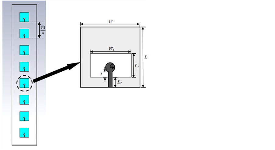
Figure 1. A 1 × 8 array of circular MSAs (antenna type A).
 (a) (b)
Figure 2. A 1 × 8 array of circular MSAs and U-shaped reflector (antenna type B). (a) Perspective view; (b) Side view.
azimuth pattern to evaluation pattern (AZ:EL), of the array antenna type A and B are 97.4˚:8.4˚ and 89.4˚:8.3˚, respectively.
3. EBG Configuration
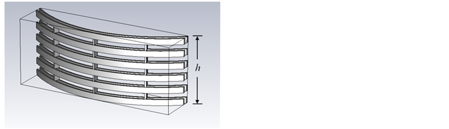
In this section, the modified array antenna type B has been increased the gain by using new technique of EBG structures instead. The conventional method for gain increment, a lot of elements will be added in the array, which causes the dimension of antenna is too long and its weight is too heavy. Moreover, the great number of electromagnetic energy will be lost inside the phasing line. From our study, we found that the proper structure of EBG is capable to enhance the gain of antenna as the additional resonant circuit which installed at front of the array panel. Furthermore, the EBG structures can be appropriately shaped for reducing the side and back lobes of the directional antenna too [17] [18] . From investigation, the sector of cylindrical woodpile EBG structures [19] are more suitable for the antenna type B. Figure 3 shows the geometry of the curved woodpile EBG structures with two layers of the different diameters. The parameters for these structures are the filament thickness or diameter (w), the radius (R), the height (h), the number of radial filaments (Nrad), and the number of rings (Nring) of the curved. To implement the curved woodpile EBG, we have used alumina rods (rectangular cross section) with parameters εr = 8.4 and  = 0.002. The parameters are given as follow [20] with w = 0.05λ, R = 3.05λ, h = 1.23λ, Nrad = 3, and Nring = 2.
4. Results and Discussions
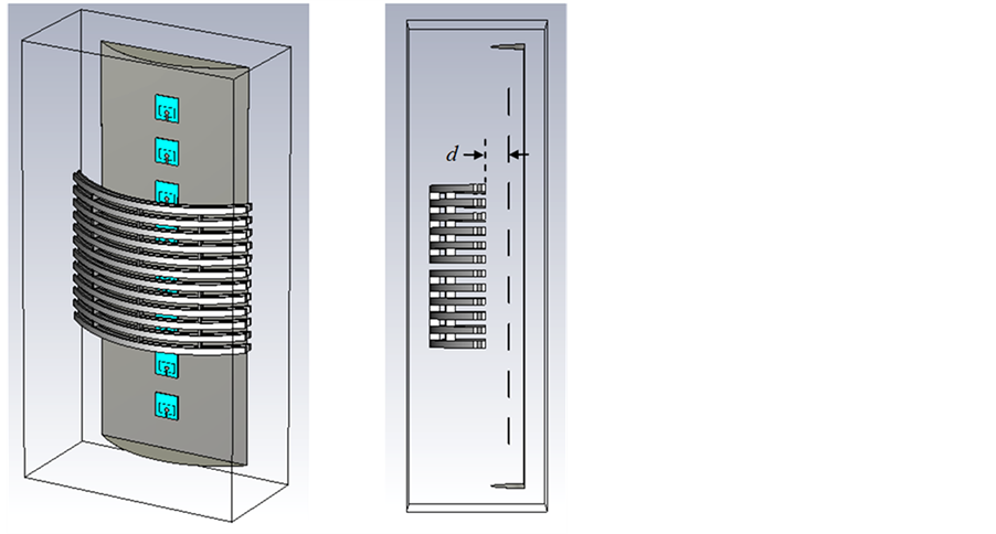
The gain improvement of 1 × 8 array of circular MSAs and U-shaped reflector with curved woodpile EBG structures (antenna type C) was simulated by CST software as shown in Figure 4.
 (a)
(a) (b)
(b)
Figure 3. The geometry of the sector of curved woodpile EBG structures. (a) Perspective view; (b) Top view.
 (a) (b)
Figure 4. A 1 × 8 array of circular MSAs and U-shaped reflector improved gain with curved woodpile EBG structures (antenna type C). (a) Perspective view; (b) Side view.
The design parameters of the gain improvement for an antenna type C are the radius (R), the distance between a 1 × 8 array of circular MSAs and curved woodpile EBG structures (d), and the height of curved woodpile EBG (h). Firstly, we look at the effect of the variation of R, d and h are fixed at 0λ and 1.23λ, respectively. Figure 5 shows the gain against the R at operating frequency of 2.1 GHz. The highest gain of 18.72 dB is provided at R is around at 3.34λ. Also, the appropriate HPBW in the H-plane appears at same radius of R of curved woodpile EBG, while its HPBW will be enlarged when the dimension of R increased. Secondly, we have investigated the effect of the distance d, while R and h are fixed at 3.34λ and 1.23λ, respectively. We note that the highest gain of 18.72 dB is achieved when d = 0λ as shown in Figure 6. Next, we have studied the effect of the h variation versus the gain, R and d are fixed at 3.34λ and 0λ, respectively, thus its result is improved as shown in Figure 7. We found that the gain is increased from 18.72 dB to 20.84 dB at h equals to 3.91λ approximately. Although the gain increases when h also increases, while h is higher than 5.25λ, it will be mismatched and operating frequency of bandwidth will be shifted to the undesired frequency.
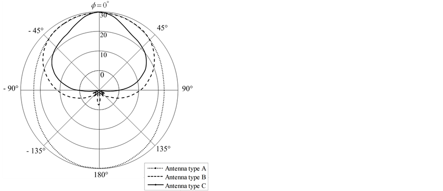
Finally, the highest gain of an antenna type C is optimized with R = 3.34λ, d = 0λ, and h = 3.91λ. The S11 (−10 dB) of the antenna type A, B, and C, covered 1.920 to 2.170 GHz, which are wide enough and can be well utilized for 3G base station as shown in Figure 8. Figure 9 shows the normalized radiation patterns at 2.1 GHz of the antenna type A, B, and C. Although its HPBW of the antenna type C will narrow, but it can cover the desired service area of base station for mobile phone and still provides the high gain. Also, the HPBW, the Side Lobe Level (SLL), and the gain of the antenna type A, B, and C are shown in Table 1.

Figure 5. Simulated the gain against R.

Figure 6. Simulated the gain against d.

Figure 7. Simulated the gain against d.
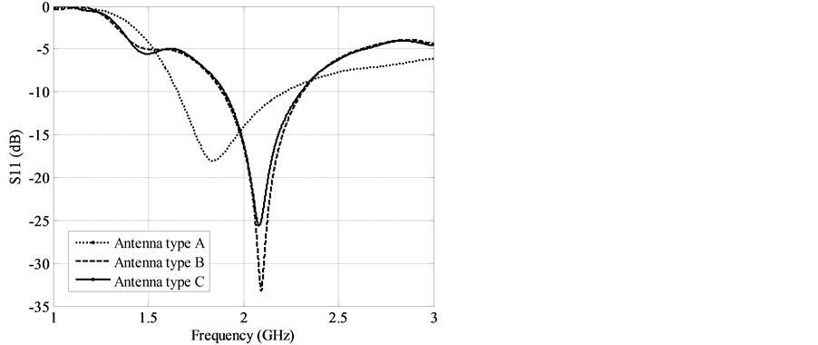
Figure 8. Simulated the reflection coefficient.
 (a)
(a) (b)
(b)
Figure 9. Simulated the normalized radiation patterns. (a) H-Plane; (b) E-Plane.

Table 1. Results of simulation.
5. Conclusion
This paper presented a sector antenna for mobile base station by modifying the omnidirectional MSAs array to be the directional antenna by adding U-shaped reflector and increasing its gain with new technique, additional curved woodpile EBG structures. From the results, explicitly, the directive gain of the proposed antenna was increased around 3 dB when such EBG structures were added, while its length of array was not enlarged. The most important technique for this accomplishment is the EBG structures that must be appropriately designed and calculated, especially the radius of the sectorial cylinder of woodpile EBG structures. The most proper radius of 3.34λ, the distance between a 1 × 8 array of circular MSAs and curved woodpile EBG structures of 0λ, and the height of curved woodpile EBG of 3.91λ can provide the moderately highest gain of 20.84 dB at the operating frequency of 2.1 GHz. Therefore, this proposed antenna accords to the requirements and is appropriated for a sector antenna of mobile base station.
Acknowledgements
This work was supported by the Research Department Institute of Engineering, Suranaree University of Technology, Nakhon Ratchasima, Thailand.
References
- Bahl, J.J. and Bhartia, P. (1980) Mircostrip Antennas. Artech House, London.
- Bhartia, P., Bahl, I., Garg, R. and Ittipipoon, A. (2000) Mircostrip Antennas Design Handbook. Artech House, London.
- Kumar, G. and Gupta, K.C. (1985) Directly Coupled Multiple Resonator Wide-Band Microstrip Antenna. IEEE Transactions on Antennas and Propagation, 33, 588-593. http://dx.doi.org/10.1109/TAP.1985.1143639
- Pozar, D.M. (1985) Microstrip Antenna Aperture-Coupled to a Microstripline. Electronics Letters, 21, 49-50. http://dx.doi.org/10.1049/el:19850034
- Huynh, T. and Lee, K.F. (1995) Single-Layer Single-Patch Wide Band Microstrip Antenna. Electronics Letters, 31, 1310-1312. http://dx.doi.org/10.1049/el:19950950
- Yang, F., Zhang, X., Ye, X. and Rahmat-Samii, Y. (2001) Wide Band E-Shaped Patch Antennas for Wireless Communications. IEEE Transactions on Antennas and Propagation, 49, 1094-1100. http://dx.doi.org/10.1109/8.933489
- Lo, T.K., Ho, C.-O., Hwang, Y., Lam, E.K.W. and Lee, B. (1997) Miniature Aperture Coupled Microstrip Antenna of Very High Permittivity. Electronics Letters, 33, 9-10. http://dx.doi.org/10.1049/el:19970053
- Yang, F. and Rahmat-Samii, Y. (2009) Electromagnetic Band Gap Structures in Antenna Engineering. Cambridge University Press, Cambridge.
- Elayachi, M., Brachat, P. and Ratajczak, P. (2006) EBG Identification by the Reflection Phase Method (RPM) Design for Application WiFi Antenna. Proceedings of the 1st European Conference on Antennas and Propagation, Nice, 6-10 November 2006, 1-5.
- Joannopoulos, J., Meade, R.D. and Winn, J.N. (1995) Photonic Crystals: Molding the Flow of Light. Princeton University Press, Princeton.
- Gonzalo, R., de Maagt, P. and Sorolla, M. (1999) Enhanced Path-Antenna Performance by Suppressing Surface Waves Using Photonic-Bandgap Substrates. IEEE Transactions on Microwave Theory and Techniques, 47, 2131-2138. http://dx.doi.org/10.1109/22.798009
- Yang, F. and Rahmat-Samii, Y. (2003) Microstrip Antennas Integrated with Electromagnetic Bandgap (EBG) Structures: A Low Mutual Coupling Design for Array Applications. IEEE Transactions on Antennas and Propagation, 51, 2936-2946. http://dx.doi.org/10.1109/TAP.2003.817983
- Llombart, N., Neto, A., Gerini, G. and de Maagt, P. (2005) Planar Circularly Symmetric EBG Structures for Reducing Surface Waves in Printed Antennas. IEEE Transactions on Antennas and Propagation, 53, 3210-3218. http://dx.doi.org/10.1109/TAP.2005.856365
- Illuz, Z., Shavit, R. and Bauer, R. (2004) Micro-Strip Antenna Phased Array with Electromagnetic Band-Gap Substrate. IEEE Transactions on Antennas and Propagation, 52, 1446-1453. http://dx.doi.org/10.1109/TAP.2004.830252
- Md Tan, M.N., Rahman, T.A., Rahim, S.K.A., Ali, M.T. and Jamlos, M.F. (2010) Antenna Array Enhancement Using Mushroom-Like Electromagnetic Band Gap (EBG). 2010 Proceedings of the 4th European Conference on Antennas and Propagation (EuCAP), Barcelona, 12-16 April 2010, 1-5.
- Chawanonphithak, Y. and Phongcharoenpanich, C. (2007) An Ultra-Wideband Circular Microstrip Antenna Fed by Microstrip Line above Wide-Slot Ground Plane. Asia-Pacific Conference on Communications, Bangkok, 18-20 October 2007, 99-102.
- Weily, A.R., Horvath, L., Esselle, K.P., Sanders, B. and Bird, T. (2005) A Planar Resonator Antenna Based on Woodpile EBG Material. IEEE Transactions on Antennas and Propagation, 53, 216-223. http://dx.doi.org/10.1109/TAP.2004.840531
- Lee, Y., Lu, X., Hao, Y., Yang, S., Evans, J.R.G. and Parini, C.G. (2009) Low Profile Directive Millimeter-Wave Antennas Using Free Formed Three-Dimensional (3D) Electromagnetic Band Gap Structures. Transactions on Antennas and Propagation, 57, 2893-2903. http://dx.doi.org/10.1109/TAP.2009.2029299
- Lee, Y., Lu, X., Hao, Y., Yang, S., Evans, J.R.G. and Parini, C.G. (2010) Narrow-Beam Azimuthally Omni-Directional Millimetre-Wave Antenna Using Free Formed Cylindrical Woodpile Cavity. IET Microwaves, Antennas and Propagation, 4, 1491-1499. http://dx.doi.org/10.1049/iet-map.2009.0224
NOTES

*Corresponding author.