Journal of Surface Engineered Materials and Advanced Technology
Vol.2 No.1(2012), Article ID:16991,10 pages DOI:10.4236/jsemat.2012.21001
Ultrasonic Corrosion-Anodization: Electrochemical Cell Design and Process Range Testing
![]()
1Department of Mechanical and Manufacturing Engineering, University of Cyprus, Nicosia, Cyprus; 2National Science Foundation, Nanomanufacturing Program, Arlington, USA.
Email: kpolychronopoulou@gmail.com
Received August 10th, 2011; revised September 17th, 2011; accepted October 28th, 2011
Keywords: Titanium; SEM; Stress Corrosion; Polarization; Anodic Dissolution
ABSTRACT
Titanium was used in the present work as the test metal for the first ultrasonic corrosion anodization (UCA) study, because of its important photonics and biomedical applications. The electrochemical cell design was implemented and tested under various experimental conditions combinations (e.g. electrolyte concentration, duration, temperature, ultrasound presence or absence, oxygen presence, etc.) in order to investigate the effect of those parameters in the cracks propagation in Ti-foils. It was found that an increase of cracks takes place when oxygen is provided in the electrolyte solution and when ultrasound is applied. The results presented in the current study could be exploitable towards design of materials having dendritic morphologies, applicable in a wide range of processes from photovoltaics to biocompatible materials.
1. Introduction
A number of current technological advances hinge on materials and coatings with internal random branching tree (dendritic) fractal geometrical architectures [1]. Such statistically self-similar forms, including Brownian trees and dendrites, are of course familiar and abound in both inanimate and animate natural structures such as snowflakes, rivers, corals, plant and animal tissues etc. Their ubiquitous presence and morphological evolution stems from their optimal function in transport of matter, energy or information (e.g. via electrical charge) between a 3D volume domain, often across 2D interface surfaces, through a 1D conduit network to a 0D collection or distribution location. Similar functionality is clearly essential also to a number of modern advanced applications, such as photoelectrodes of excitonic solar cells, hydrogen storage and battery media, electromagnetic antennae and shielding materials, porous filtration membranes and catalytic substrates, biocompatible coatings of osseous implants, vascular scaffolds for tissue engineering etc.
Technological need for such custom-tailored, random dendritic fractal structures across multiple dimensional scales has stirred recent interest in their scalable production by design, without recourse to costly, deterministic Euclidean layered manufacturing via lithography or solid freeform fabrication [2]. This poses technical challenges in control of the requisite diffusive and/or reactive material aggregation, erosion and/or transformation processes, which in nature employ a variety of selforganization, self-replication and self-assembly mechanisms for a plethora of materials and generator patterns down to the nanoand atomic scales. An example of such an electrostatic erosion method for material ablation imitating a lightning discharge has been shown to produce discharge structures [3]. Such Lichtenberg figures are generated in dielectric polymers irradiated by a highenergy electron beam (in a linear accelerator of Van der Graaf generator), and then grounded so that local electrical breakdown avalanches to excavate a vascular pattern. However, such high-voltage processing is material-specific and problematic to control and scale up for affordable and safe manufacturing.
This article introduces ultrasonic corrosive anodizetion (UCA), a new controllable and scalable fabrication process for an erosion of random dendritic fractal patterns by design, in a class of metallic conductor materials. UCA employs stress-corrosion cracking in an anodizetion cell, under resonant ultrasound excitation of the processed structures. The process originates from the familiar passive (and often catastrophic) corrosion fatigue of metals exposed to an electrochemically active environment under dynamic stresses. A combination of electrochemical solvation with mechanical microfracture is known to initiate cracks, propagating transgranularly and/or intergranularly, i.e. along grain boundaries, lattice discontinuities, segregated impurities etc. [4]. Ultrasonic waves in a liquid medium, on the other hand, are understood to induce failure by cavitation on metal surfaces due to nucleation and collapse of microbubbles, inducing localized evaporative heat transfer and intense stresses [5]. Despite the maturity of both fields, their synergistic combination towards a controllable manufacturing process is, to the authors’ knowledge, attempted for the first time. The paper focuses on the design and implementation of a suitable experimental UCA cell and a preliminary study of the process-structure ranges obtainable within its parameter boundaries of operating conditions.
Titanium will be used as the test metal for this first UCA study, because of its important photonics and biomedical applications, stemming from its biocompatibility and anodic oxidation into TiO2, a popular UV-matched wide bad gap semiconductor. In the presence of oxygen or water traces at lower temperatures, Ti instantly forms this passivating TiO2 film (typically <10 nm thick), with a n-type anatase open structure. This protective film is attacked in highly reducing acids such as hot concentrated HF, HCl, H2SO4, fuming HNO3 and anhydrous N2O4 gas or methanol-halide solutions. The thermodynamics and kinetics of the reaction/diffusion-limited formation and rupture of this oxide film have been established in the literature, mostly through empirical models of anodic dissolution and mechanical fracture for Ti and other metals [4].
In particular, Kononen et al. [6] studied if the pure titanium is susceptible to stress corrosion cracking in a topical fluoride solution by using a U-shape specimen exposed in different time periods. Throughout the paper it was concluded that topical fluoride solutions can cause SCC of commercially pure titanium. Nakamura et al. [7] investigated titanium SCC by using two different methods, the Slow Strain Rate Tensile method and the Constant load test. The sample was immersed in is 20% NaCl solution at 90˚C. The primary cracks was found to be approximately 10 μm. Sanderson et al. [8] in their paper dealt with U-bent tests and dynamic tensile tests which showed that SCC are formed in titanium alloys in NaCl environment at room temperature. It had been found that the cracks are developed because the chemical polishing creates a layer of very small hydride precipitates. Roy et al. [9] studied SCC of titanium by using double cantilever-beam technique. The sample was immersed in acidic brine pH 2.7 containing 5wt% NaCl at 90˚C continuosly. Simbi et al. [10] investigated the intergranular stress corrosion cracking of pure titanium in methanol hydrochloric acid at room temperature. The surface of the specimen was chemically polished in a solution containing 40% HF and 70% HNO3 concentrated acids. Hsiung et al. [11] studied the corrosion resistance of pure titanium in a mixture of 1% NaCl and 0% - 1% NaF at a constant pH of 6 under different elastic tensile strains. The results of polarization resistance reveal that the Rp decreased on increasing the tensile strain and increase in NaF concentration.
In the present work, for the first time, the design and experimental apparatus testing was evaluated towards formulating an appropriate set of conditions for creating a tree shape morphology on the titanium surface. In order to achieve the above goal ultrasonic loading was used for promoting crack propagation. In ultrasonic loading, cracks propagate during the tensile part of each cycle, while during the compression part crushing, attrition and dissolution of surface oxide films widen the conduits of the corrosive medium to the crack. All cracking network pictures taken from SEM are processed by the Matlab software to show the percentile amount of cracks.
2. Materials and Methods
2.1. Device Parts
The experimental device settled for the SCC tests is presented on Figure 1.
The set up should be aligned with some vital criteria: 1) the sample must be stable during ultrasonic waves, 2) the electrolyte in which the sample is to be immersed must have the capability of increasing the temperature up to 200˚C and keep it constant at any stage, 3) during the experiment air or oxygen must be provided (air flow rate = 3.77 × 10⁻⁶ m3/s) to the electrolyte so as to be homogeneously oxygenated under stirring, 4) the device must be also able to use electrochemical anodization to polarize
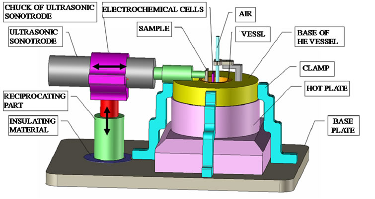

Figure 1. (a) Components and (b) images of the designed UCA experimental device.
the sample and enhance the corrosion, 5) the results must be repeatable. Designing and programming were done at Software TopSolid and the machining of pieces on Computer Numerical Control Mill and Turn.
Further, some important pieces of the experimental set up, the way that has been designed and manufactured is described. The biggest part of the device is the base plate. In order to fulfill one of its basic characteristics which is that the results must be repeatable, a common base was manufactured on which all the parts of the device are stable on the base plate. The base of the vessel is placed on a hot plate. It is made of stainless steel and brass and both materials are heavy in order to be stable. Also, these materials have a huge heat capacity in order to keep the temperature of the electrolyte stable. The vessel of the cell (Figure 2) is the most important part of the experimental set up. It must have some basic characteristics, such as 1) keep the sample stable, 2) be chemically resistant, 3) keep the platinum part stable in front of the sample at 10mm in order for the electrochemical cell process to take place and 4) the melting point of this material should be above 200˚C.
The vessel is made of polytetrafluoroethylene (PTFE). It is chemically and wear resistant [12] and its melting point is at 250˚C. The vessel was designed as follows: Inside the vessel there are two parallel flat surfaces (1.1,1.2) and a knob (1.3). The sample was fixed on surface 1.1. The part 2 which holds the sample was set up inside the knob. The platinum electrode is situated on the surface 2.1 of the part 2, at a distance of 10 mm from the sample. The part 3 is the one which compresses the sample and the platinum part so as to be stable. Part 4 is the cup of the vessel and it has four slots . The 4.1 is used for the sample to go up, the 4.2 is for the thermometer and the glass rod which supplies air to the vessel. In order for the experimental results to be trustworthy and repeatable, the same procedure had to be followed in all the samples.
2.2. Materials
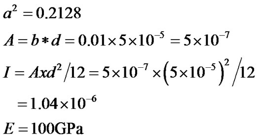
The material used was pure titanium foil (99.6%) of 0.05 thickness. Titanium is a light metal having a density of about 4540 kg/m3 and has a Modulus of Elasticity of 100 × 109 Pa [13]. The purity level, as provided by the manu-
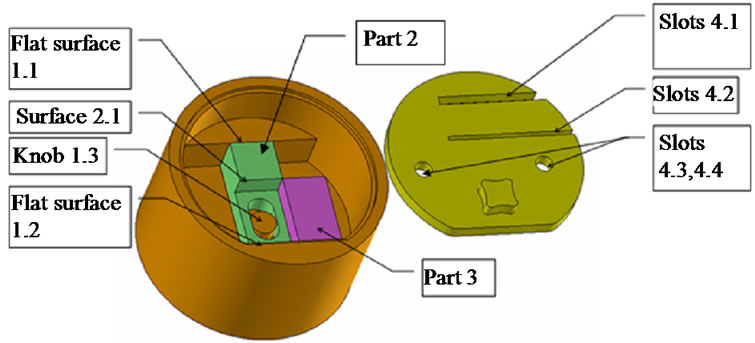
Figure 2. Schematic of the vessel of the electrochemical cell.
facturer in (ppm) is C 200, N 120, H 50, Fe 1500, O 1500 [14]. The dimension of the sample was 22 mm × 10 mm. Before mounting the sample, washing of it with acetone, ethanol and deionised water was applied. After finishing the experiment, the sample had to be washed again with isopropanol and deionised water. Trichloroacetic acid (CCl3COOH) 100 mM and 200 mM concentration was used as electrolyte. The pH of the electrolyte (Trichloroacetic acid) was measured to be 1.54. The volume of the electrolyte in the vessel of the cell was 20ml. In the case that anodization was applied the current density was set to 0.1 mA/cm2.
2.3. Characterization
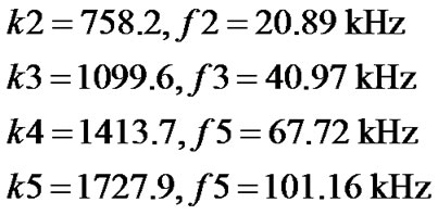
The morphology of titanium foils was characterized using Scanning Electron Microscope (SEM). The largest stress is found at the point where the sample is bent. Further, an image processing code was created in the Matlab software, example is provided in Figure 3, which processes the image from SEM, and shows the average percentage of the cracked surface that has been created in each image. Then we compare all the results of the experiments in order to come to conclusions about the effect of the different conditions applied on each experiment.
2.4. Ultrasound Corrosion Cracking Testing
The performance of the materials prepared was tested under ultrasound corrosion testing conditions. The set of experimental conditions is presented in Table 1. Vital parameters for the process, namely presence of air, electrochemical anodization, temperature, concentration of trichloroacetic acid, and time, were studied. The reference sample (Figure 4) is the one that was tested under the experimental conditions 0/0/0/0/0/0. In particular, the sample (22 × 10 × 0.05 mm) is placed for four hours in the experimental vessel without ultrasonic loading or electrochemical anodization, in the absence of air whereas the measurement was performed at room temperature in trichloroacetic acid (100 mm).
Before starting the experiment, the titanium foil was
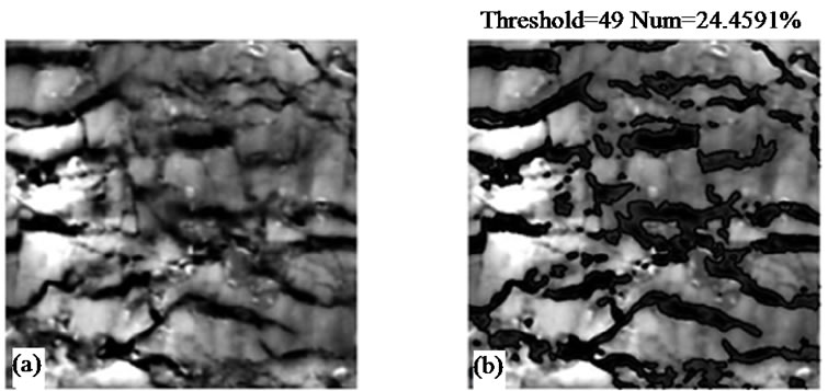
Figure 3. (a) Image from SEM, (b) Processed image using code written in Matlab.
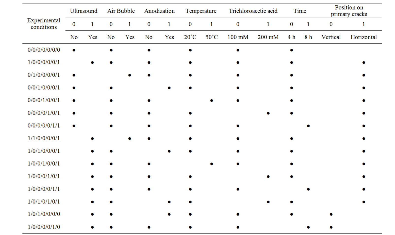
Table 1. Matrix of experimental conditions applied in the present work.
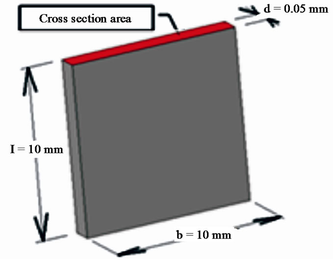
Figure 4. Dimension of the sample.
examined in SEM and it was observed that on the sample surface there were some primary cracks. These were created due to the sample machining. All primary cracks are similarly oriented. Several experiments were in which the primary cracks were in a horizontal or vertical position in relation to the electrolyte surfaces conducted.
2.5. Natural Frequency
The measure of natural frequency depends on the composition of the sample, its size, structure, weight and shape [15].
 (eq.1)
 (eq.2)
 (eq.3)
 (eq.4)
 (eq.5)
 (eq.6)
 (eq.7)
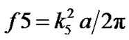
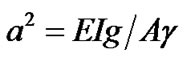
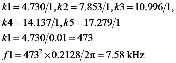
where f 1, 2, ∙∙∙, n: Natural frequency E: Modulus of elasticity 
I: Second moment of area g: Gravity A: Cross section area
γ: weight of the bar per unit volume l: Length of the bar The frequency of Ultrasonic loading applied in the sample was 40 kHz. As observed from the formulas [15] below this is very close to the third natural frequency but without counting for the damping of the electrolyte which is in the sample. In order for resonance to be achieved further study will be needed.
In a similar way,
3. Results & Discussion
3.1. Determining the Effect of Each One Parameter on Cracks Initiation and Propagation
In the absence of ultrasound stress corrosion it was found that the average length of the cracks (in microns) of the reference sample (Figure 5) was about 4.19%. The average percentage of the reference sample represents the primary cracks found in the sample.
Next objective of this study was to explore the contribution of each one of the important experimental conditions reported above (e.g. temperature, electrolyte concentration, etc.), separately in order to decouple their effect and find out which conditions affect the increase of the size of the primary cracks. For clarification, it should be stated that in all samples below the primary cracks are horizontal in relation with the electrolyte surface.
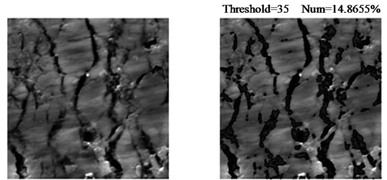
Ultrasonic loading: First, a Ti-sample was examined under experimental conditions 1/0/0/0/0/0/1(Figure 6).
The difference of this sample with the reference one was that ultrasonic loading was applied in this case on its upper end. The average percentage of the primary cracks
 (a) (b)
Figure 5. Reference sample (a) Image from SEM; (b) Processed image using code written in Matlab.
 (a) (b)
Figure 6. Ti-specimen tested experimental conditions 1/0/0/0/0/0/1 (a) Image from SEM; (b) Processed image using code written in Matlab.
has been doubled (9.0%) compared to the reference sample due to the mechanical effect of ultrasound and the propagation of the cracks under the ultrasonic field.
Air presence: As a next step, another Ti-sample examined under experimental conditions 0/1/0/0/0/0/1. In this case, oxygen was provided in the electrolyte solution. The average percentage of cracks was 4.97%. The chemical corrosion due to air bubbling led to a small increase of cracks.
Electrochemical anodization: Another Ti-sample was tested under experimental conditions 0/0/1/0/0/0/1. A platinum electrode was put at 10mm distance from the sample in order for the electrochemical anodization to take place. In this case the average percentage was found to be 2.9%. One observes decreasing of the cracks compared to the average percentage of the reference sample which was 4.2%. Under conditions of anodization which can be considered a dynamic condition, the rate of oxide development and intrinsic characteristics of the material (e.g. coherency) and at the same time the adherence of the formed oxide with the underlying metal seem to change with time and this could lead to a decrease of cracks [16].
Electrolyte temperature: By increasing the electrolyte temperature to around 50˚C, (Sample 4) (0/0/0/1/0/0/1) there was a decrease in the percentage of the cracks (2.50%).
Based on the previously-presented results, it can be stated that the experimental conditions which result in an increase of the size of primary cracks are ultrasonic loading and provision of air to the electrolyte for the reasons explained above, where mechanically-forced or chemical-assisted corrosion was performed.
3.2. Ultrasound Loading: Investigating the Impact of Different Parameters on Cracks Formation
In the next group of experiments the ultrasonic loading is applied in all the cases explored. Apart from this, in each experiment there is a different experimental condition applied. In all of the samples below the primary cracks are horizontal in relation to the ultrasonic loading. The first experiment (1/0/0/0/0/0/1) has already been discussed previously in section 3.1, i.e. in which the ultrasonic loading is applied and the percentage of the primary cracks increases (compared to the reference sample).
The next experiment (1/1/0/0/0/0/1) is a combination of ultrasonic loading and provision air to the electrolyte. The percentage of the cracks is increasing by 3.5% in relation to the previous experiments where only the ultrasonic loading was applied. When the sample is exposed to a combination of ultrasonic loading and electrochemical anodization (Figure 7) (1/0/1/0/0/0/1) one observes that there is an increase in the size of primary cracks. The size of the cracks was increased by another 6.5% compared to the experiment that only the ultrasonic loading was applied (1/0/0/0/0/0/1). This can be explained by the fact that an oxide film is probably formed which is more transparent to electrons and the propagation of cracking is kinetically enhanced [16].
By comparing the experiments 0/0/1/0/0/0/1 (mechanical stress: ultrasonic load) and 1/0/1/0/0/0/1 (mechanical and chemical stress: ultrasonic load in the presence of air), one observes that in the first sample the cracks decrease and in the second sample they increase (quadrupled) compared to the reference. When there is no application of ultrasonic loading in the sample the primary cracks are covered but when there is ultrasonic loading covering of the cracks is not allowed. The combination of ultrasonic loading and electrochemical anodization helps in the increase of primary cracks. This is an expected trend since it is already known from the literature that the chemical surroundings and the mechaniccal forces facilitate the corrosion cracking [17-21].
The next step was a combined exposure of the Tisample to ultrasonic loading (1/0/0/1/0/0/1) and increase of temperature from room temperature up to 50˚C - 55˚C. The percentage of the primary cracks increased in rela-
 (a) (b)
Figure 7. Ti-specimen tested under experimental conditions 1/0/1/0/0/0/1 (a) Image from SEM; (b) Processed image using code written in Matlab.
tion to the reference sample and the results of the experiment are close to those of the experiment which was at room temperature (1/0/0/0/0/0/1). The result of the experiment 0/0/0/1/0/0/1 was decreased in relation to the reference sample. Through these two results one observes that the electrolyte’s temperature 50˚C - 55˚C does not affect the increase in the percentage of the cracks. This result could be explained based on the fact that 50˚C - 55˚C is not so high temperature to cause any significant changes in the formed phases. It is known that temperature controls electrochemical kinetics and the solubilities in the solution environment. There is a critical temperature where initiation of crackings starts due to the presence of corrosion precursors (e.g. TixCly species formation) at those temperatures. It has been reported that in the case of failure by hydrogen embrittlement, increasing the temperature can lead to cracking reduction for some systems because of the low concentration at very localized sites in microdomains in the metal.
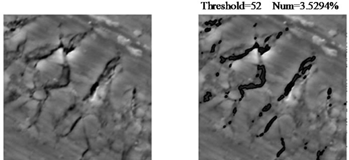
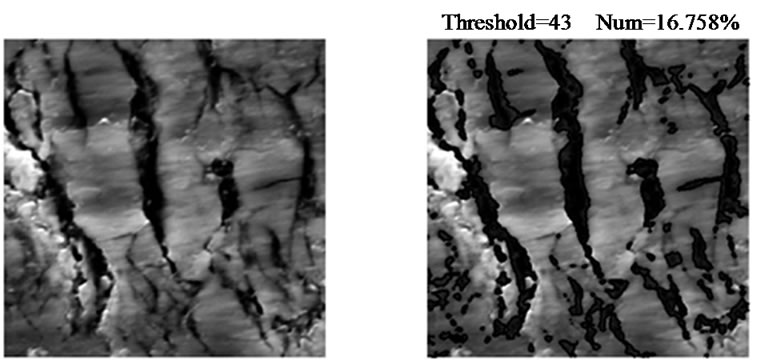
Exposure of the sample to an increased electrolyte concentration (Figure 8) (1/0/0/0/1/0/1) (doubled concentration from 100 mM to 200 mM) led to an increase of the percentage of cracks by 15.7% compared to the results of the experiments 1/0/0/0/0/0/1. It can be stated that the increased chlorine concentration assist the fracture of the protective oxide layer by forming some stable compounds with titanium. This effect combined with the stress applied can lead to the formation of trenches due to local dissolution. At the points where trenches are formed hydrogen adsorption can occur, coming from the solution, and causing the precipitation of brittle hydrides. As it has been reported, this effect enhances the propagation of cracks in titanium [22]. By increasing the exposure time (1/0/0/0/0/1/1) from four to eight hours it was observed that the percentage of the primary cracks has been almost doubled (17.6%) compared with experiment where the duration of the experiment was 4 hours (1/0/0/0/0/0/1). This shows the control of the kinetics over cracks propagation.
Based on this group of experiments, one can conclude
 (a) (b)
Figure 8. Ti-specimen tested under experimental conditions 1/0/0/0/1/0/1 (a) Image from SEM; (b) Processed image using code written in Matlab.
that the size of the primary cracks is increased due to the following conditions: ultrasonic loading, provision of oxygen to the electrolyte, electrochemical anodization, increase of concentration of electrolyte and duration of the experiment.
In the next experiment (Figure 9) the ultrasonic loading, electrochemical anodization and the electrolyte solution with increased concentration were chosen since it was found that they enhance the size of the primary cracks. The code of the experiment is 1/0/1/0/1/0/1. The combination of these three conditions has increased the size of cracks (22.6%) by 2.5 times in comparison to the results of experiment 1/0/0/0/0/0/1 implying the synergistic activity in this case.
3.3. Effect of Sample Positioning to the Ultrasound Loading
In the next two experiments the sample is positioned in such a way that the primary cracks are in a vertical position in relation to the ultrasonic loading. Two experiments were conducted, namely 1/0/1/0/0/0/0 and 1/0/0/0/0/1/0 according to the Table 1. One observes that the results of the experiments are decreased compared to the corresponding results when the sample was in a horizontal position in relation to the ultrasonic loading (1/0/1/0/0/0/1, 1/0/0/0/0/1/1). For this reason there was no sequel to these experiments since when the sample is in vertical position these is no increase on the percentage of the primary cracks.
By situating the primary cracks in a vertical position their percentage is not increased because of the inherent difficulty in cracks opening during the tensile part, and as a consequence the electrolyte diffusion met there a barrier to enter the cracks. In contrast, when the cracks are situated in a horizontal position the cracks open during the tensile part and the electrolyte diffuses relatively easily into the cracks and remains there during the compression part. In this way the size and the depth of the cracks is increasing.
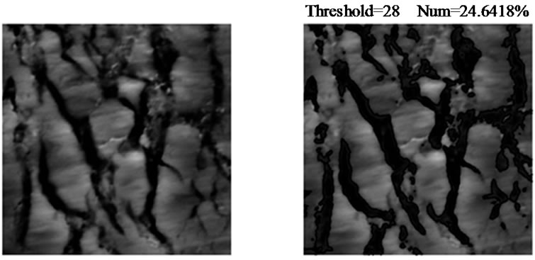 (a) (b)
Figure 9. Ti-specimen tested under experimental conditions 1/0/1/0/1/0/1 (a) Image from SEM; (b) Processed image using code written in Matlab.
3.4. Cross-Sectional Imaging
Cross section is another way to confirm that ultrasonic loading contributes in the corrosion of titanium. The samples examined are 1/0/1/0/1/0/1 and were compared to the reference sample. For this reason, samples were prepared in cross section and examined through SEM. Each sample was cut vertically in relation to the cracks in order for its cross section to be exposed and examined.
The reference sample (0/0/0/0/0/0) has undergone the same procedure of being cut and through SEM there were no cracks observed (Figure 10(a)). On the contrary, in sample 1/0/1/0/1/0/1 the cracks of the surface continue to exist in the material having a depth of almost 10 μm (Figure 10(b)). For this reason it can be assumed that these cracks have been created under the experimental conditions applied.
4. Conclusions and Further Work
In summary, this paper illustrated the design and operation of a hybrid electrochemical-mechanical anodization cell for corrosion fatigue of Ti foils under ultrasonic loading. Preliminary results based on SEM microstructures of the generated crack patterns were observed on the surface and section of the specimens, and the cracked areal percentile fractions were determined at the range boundaries of the essential process conditions, i.e: ultrasonic amplitude, oxidant flow, anodizing current, electrolyte temperature, acid concentration, process time and initial cracking. As further work, a full parametric study based on a factorial design of experiments for combinations of the most effective process conditions, along with a sensitivity analysis of the process inputs and outputs for real-time monitoring and feedback control, are currently underway. However, the presented preliminary data on the resulting dimensional and morphological variety of crack patterns under ordinary manufacturing conditions and infrastructures, suggest the potential of ultrasonic corrosive anodization as a feasible scalable production process for controlled random branching fractal architectures. It should be noted that the tree-like crack (negative) cavities can serve for molding of similarly shaped (positive) asperities from a variety of materials, such as polymeric nanofiber membranes via electrospinning [23].
In addition, UCA of other alternative metal foils is currently researched: Zinc, which promptly corrodes and forms ZnO in water with CO2 content or bubbled oxygen at 60˚C and in dilute acidic conditions; and Tin, which forms stannic oxide (SnO2) readily in HNO3 and hot HBr or HI acids, especially when in electrical contact with a nobler cathode (Cu or Ni). Moreover, research is underway on localized anodic oxidation and crack propagation over a predefined branching network of grain boundaries
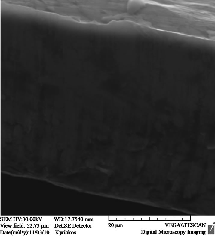 (a)
(a)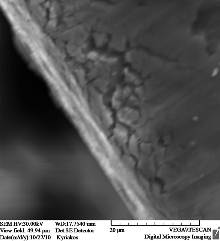 (b)
(b)
Figure 10. Cross sectional images obtained over the reference sample (a) and 1/0/1/0/1/0/1 (b).
or internal surfaces, forming a fractal structure by design down to the nanoscale. Such networks can be pre-shaped e.g. in a nanocrystalline metal film deposited by physical vapor deposition (PVD), or embedded in nanogranular materials via grain refinement and distortion by severe plastic deformation (SPD) processes, such as hydrostatic extrusion, high pressure torsion etc. [24]. In such preengineered media, customized dendritic fractal structures can be fabricated by UCA via localized anisotropic corrosion, through directed perfusion by the electrolyte of the conduit network embedded in the film.
Nonlinear dependencies of the degree of corrosive cracking on the process conditions were realized via the synergy of anodic oxidation with mechanical fracture: For example in the absence of ultrasonic loading, parameters such as anodization current and bath temperature, promoting growth of the oxide film via the Arrhenius activation conditions for oxidation, lead to decreased cracked percentile areas. This is apparently due to a concomitant reactive and diffusive mass transport tending to minimize free energy via reduction of the exposed surface, therefore smoothing and closing incipient cracks over time. On the contrary when ultrasound is applied, the same conditions are shown to promote cracking over the short periods of ultrasonic vibration. This suggests that cracks propagate during the tensile part of each ultrasonic cycle, while during the compression part crushing, attrition and dissolution of ruptured oxide films widen the pathways of the corrosive medium to penetrate and promote further cracking. Corroboration of this mechanism behooves time-resolved in-situ TEM or AFM observation of the cracking progress during the process, presently challenged by the high ultrasonic frequencies.
In conclusion, the ultrasonic corrosive anodization process appears as a promising method for obtaining tree-shaped material morphologies for various applications, such as solar cell photoelectrodes [25]. In photocatalytic phenomena it is known that one of the main issues is recombination between photogenerated electron-hole pairs (excitons). To enhance the photocatalytic material performance, surface texture and spatial scale of the features are important factors dominating the overall process efficiency; namely the photocatalyst surface needs to be as large as possible to absorb the incident light energy. UCA-patterned Ti/TiO2 photoelectrode surfaces, functionalized with dyes and other molecules, can provide this fractal surface complexity, also ensuring a variety of local energy states for exciton generation. Similar free energy and topological features are essential for epithelial cell anchoring, multiplication and differentiation in bone implant coatings and in vascular scaffolds for tissue engineering applications.
5. Acknowledgements
Authors would like to acknowledge funding through the Nanotissue (TEXNO/YLIKA/0308(BIE)/05) and Nanoma (FP7-ICT-2007-224594) projects.
REFERENCES
- B. B. Mandelbrot, “The Fractal Geometry of Nature,” W. H. Freeman & Co, New York, 1982.
- C. C. Doumanidis, “Nanomanufacturing of Random Branching Material Architectures,” Journal of Microelectronic Engineering, Vol. 86, No. 4-6, 2009, pp. 467-478. doi:10.1016/j.mee.2009.02.024
- M. D. Noskov, A. S. Malinovski, C. M. Cooke, K. A. Wright and A. J. Schwab, “Experimental Study and Simulation of Space Charge Stimulated Discharge,” Journal of Applied Physics, Vol. 92, No. 9, 2002, pp. 4926-4934. doi:10.1063/1.1506395
- B. Craig and S. L. Pohlman, “Corrosion,” In: J. R. Davis, Ed., Metals Handbook, Vol. 13, 9th Edition, American Society for Metals, 1987.
- E. V. Skorb, D. Fix, D. G. Shchukin, H. Möhwald, D. V. Sviridov, R. Mousa, N. Wanderka, J. Schäferhans, N. Pazos-Perez, A. Fery and D. V. Andreeva, “Sonochemical Formation of Metal Sponges,” Nanoscale, Advance first, 2011.
- M. H. O. Kononen, E. T. Lavonius and J. K. Kivilahti, “SEM Observation on Stress Corrosion Cracking of Commercially Pure Titanium in a Topical Fluoride Solution,” Dental Materials, Vol. 11, No. 4, 1995, pp. 269-272. doi:10.1016/0109-5641(95)80061-1
- N. Nakamura, M. Akashi, Y. Fukaya and G. Nakayama “Stress—Corrosion Crack Initiation Behavior in aTitanium used for nuclear Waste Disposal Overpack,” Corrosion 2000 Paper 00195, NACE International, Houston, 2000.
- G. Sanderson, D. T. Powell and J. C. Scully, “The “Stress —Corrosion Cracking of Ti Alloys in Aqueous Chloride Solutions at Room Temperature,” Corrosion Science, Vol. 8, 1968, pp. 473-481. doi:10.1016/S0010-938X(68)80002-2
- A. K. Roy, D. L. Fleming, D. C. Freeman and B. Y. Lum, “Stress Corrosion Cracking of Alloy C-22 and Ti Gr-12 using Double—Cantilever-Beam Technique,” Micron, Vol. 30, 1999, pp. 649-654. doi:10.1016/S0968-4328(99)00037-2
- D. J. Simbi and J. C. Scully, “The Intergranular Stress Corrosion Cracking of Ti 155 in Methanol/HCl at Room Temperature,” Corrosion Science, Vol. 34, 1993, pp. 1743-1750. doi:10.1016/0010-938X(93)90046-J
- H.-H. Huang, “Effects of Fluride Concentration and Elastic Tensile Strain on the Corrosion Resistance of Commercially Pure Titanium,” Biomaterials, Vol. 23, No. 1, 2002, pp. 59-63. doi:10.1016/S0142-9612(01)00079-5
- D. Dascalescu, K. Polychronopoulou and A. A. Polycarpou, “The Significance of Tribochemistry on the Performance of PTFE-Based Coatings in CO2 Refrigerant Environment,” Surface and Coatings Technology, Vol. 204, No. 3, 2009, pp. 319-329. doi:10.1016/j.surfcoat.2009.07.042
- http://www.feppd.org/ICB-Dent/campus/biomechanics_in_dentistry/ldv_data/mech/basic_titanium.htm
- http://www.advent-rm.com
- W. Weaver, S. Timoshenko and D. H. Young, “Vibration Problems in Engineering,” D. Van Nostrand Company INV, Princeton, 2005, pp. 307-345.
- B. C. Syrett and R. N. Parkins, “The Effect of Sn and As on the Stress Corrosion of Cu-Zn Alloys,” Corrosion Science, Vol. 10, No. 4, 1970, pp. 197-210.
- R. A. Cottis, “Guides to Good Practice in Corrosion Control—Stress Corrosion Cracking,” National Physical Laboratory, Teddington, 2000.
- R. P. Gangloff and M. B. Ives, Eds., “EnvironmentInduced Cracking of Metals,” NACE, Houston, 1990.
- R. H. Jones and R. E. Ricker, “Stress Corrosion Cracking,” In: Metals Handbook, 9th Edition, Vol. 13, Corrosion, ASM International Metals Park, 1987, pp. 145-162.
- H. I. McHenry, D. T. Read and T. R. Shives, “Failure Analysis of an Amine-Absorber Pressure Vessel,” Materials Performance, Vol. 26, No. 8, 1987, pp. 18-24.
- A. Turnbull, “Modelling of Environment-Assisted Cracking,” Corrosion Science, Vol. 34, No. 6 1993, pp. 921- 960.
- H. O. M. Kiiniinen, E. T. Lavonius and J. K. Kivilahti, “SEM Observations on Stress Corrosion Cracking of Commercially Pure Titanium in a Topical Fluoride Solution,” Dental Materials, Vol. 11, No. 4, 1995, pp. 269-272.
- T. Christoforou and C. C. Doumanidis, “Biodegradable Cellulose Acetate Nanofiber Fabrication via Electrospinning,” Journal of Nanoscience & Nanotechnology, Vol. 10, 2010, pp. 1-8.
- K. J. Kurzydlowski, “Microstructural Refinement and Properties of Metals Processed by Severe Plastic Deformation,” Bulletin of the Polish Academy of Sciences Technical Sciences, Vol. 52, No. 4, 2004, pp. 301-311.
- M. Grätzel, “Photoelectrochemical Cells,” Nature, Vol. 414, No. 6861, 2001, pp. 338-344. doi:10.1038/35104607
Appendix
The code of Matlab software which processes the pictures from SEM is the following one.
function Num = CrackProp(thresh)
File = uigetfile('*.*');
A = imread(File,'tiff');
I = uint8(A(1:512,:));
if thresh == 'auto'
thresh = round(0.5*255*cogthresh(I));
end figure(1)
subplot(2,2,1)
imshow(I)
subplot(2,2,3:4)
imhist(I)
subplot(2,2,2)
imshow(I)
hold on Num = 100*numel(find(I <= thresh))/numel(I);
contour(I,[thresh+0.00001],'LineWidth',1.5,'Color','w')
title(['Threshold=',num2str(thresh),' Num= ',num2str(Num),'%'])
hgsave([File(1:end-4),'.fig'])
print('-djpeg',[File(1:end-4),'.jpg'])
end function CutOff = cogthresh(InputImage)
ImageSize = size(InputImage);
ImageHistogram = imhist(InputImage);
CutOff = floor(sum(ImageHistogram.*[1:256]')/sum(ImageHistogram))/255;
NOTES
*Corresponding author.